Electric Rickshaw modelling
Objective:
To Create a detailed MATLAB model of an electric rickshaw (three wheel passenger vehicle) as per details below:
- Rear wheels driven by PM brushed type motor
- Assume efficiency points of motor controller and motor
- Make an excel sheet of all input and assumed data
Since 2008, electric rickshaws (also known as electric tuk-tuks or e-rickshaws or totos or e-tricycles) have become increasingly popular in some cities as an alternative to autorickshaws and rickshaws. This popularity is due to low fuel costs and ease of use compared to rickshaws. They are widely accepted as an alternative to oil/diesel/CNG auto rickshaws. These are tricycles powered by electric motors from 650 to 1400 watts. They are mainly produced in India and China. Experts say that with systematic introduction of e-rickshaws, they can become a low-emission supplementary form of transport for low-income people, who suffer most from lack of transport facilities.
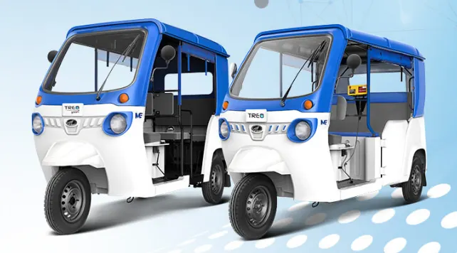
The Mahindra Treo is a revolutionary new version of an electric car, electric rickshaw and truck. Mahindra Treo is powered by advanced lithium-ion technology that delivers better fuel economy, superior ride quality and class-leading cabin space. Drive change for a better future with the Mahindra Treo.
Greater Savings
1)- Low running cost of only 50 paise per km saving up to Rs. 45,000.00 per year in fuel costs. 2)- The new powerful AC induction motor now has a maximum power of 8 kW and a higher maximum speed of 55 km/h.
3)- With 42 Nm of torque, the Treo offers best-in-class acceleration from 0 to 20 km/h in 2.3 seconds, making driving an enjoyable experience.
4)- The Mahindra Treo's 12.7 degree high grade capability makes hill climbing and overpassing easy, best in class.

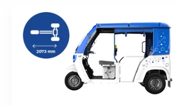
5)- Mahindra Treo with the longest wheelbase (2073 mm) offers best-in-class comfort with more legroom and easy entry and exit for all age groups.
6)- The Treo's IP 67 rated motor provides improved protection against water and dust. Built-in rear collision protection protects passengers in the event of a rear collision. An optional hardtop provides year-round weather protection.
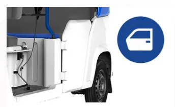
7)- Mahindra Treo provides side doors to make the ride safer for passengers.
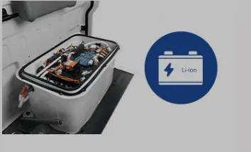
8)- Maintenance-free, lithium-ion battery with a standard warranty of 3 years and a service life of at least 150,000 km.
9)- Room frame construction with corrosion-resistant modular SMC panels without dents, easy to repair or replace.
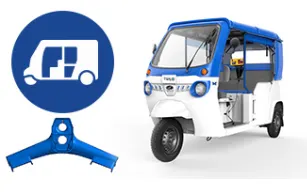
10)- remote range, speed, location, etc. monitoring for next-generation mobility* and efficient use of fleets.

11)- Larger windshield area ensures good visibility when maneuvering in heavy traffic conditions.

12)- The new Mahindra Treo is equipped with advanced Li-ion technology and has a range of 131 km (typical driving distance) on a single charge with a certified mileage of 141 km.
13)- Pollution-free and noise-free driving, which makes the Treo environmentally friendly.
14)- The kinetic energy generated during braking is returned to the battery, ensuring that energy wastage is minimized.
15) - Charging your Treo is as easy as charging your phone. Charge Treo in just 3 hours 50 minutes and Treo Yaari in 2 hours 30 minutes. A charge during a lunch break can allow you to run more than 20 kilometers. It has a portable charger so it can be charged anywhere and can be charged from a 15A outlet.
16)- Treo's drive-by-wire technology makes driving the vehicle very easy. Comfortable, noise-free, vibration-free driving gives drivers and passengers fatigue-free. Its seats are designed for the comfort of the driver and passengers. Ergonomically designed brake pedal ensures effortless braking.
17)- Treo's spacious interior ensures that everyone has enough legroom. The EV also provides a luggage compartment to connect to bus and train stations.
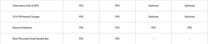
Specification: -
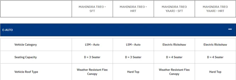
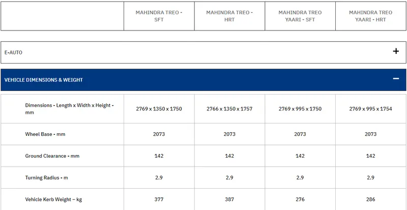
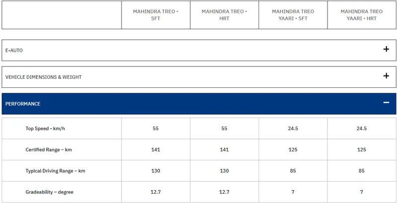
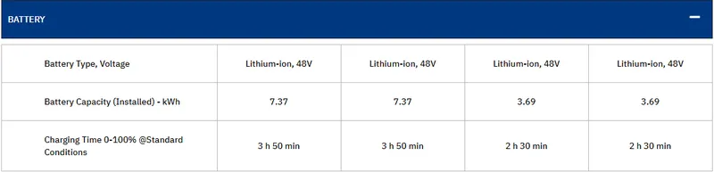
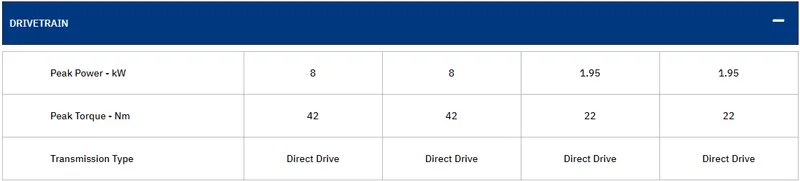
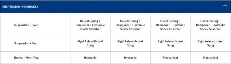

feature:-
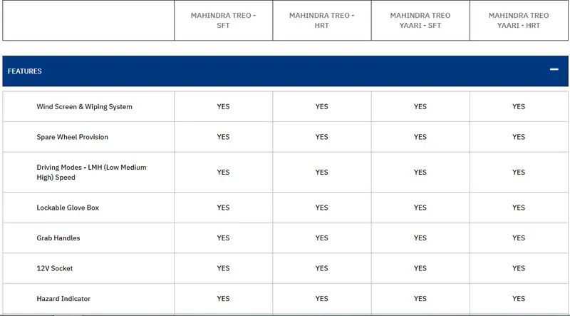
Modeling process:
- First, determine how much power the vehicle needs.
- Determine the appropriate motor based on drive power.
- Then determine the battery range and battery type based on the type of motor and controller.
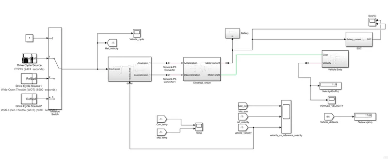
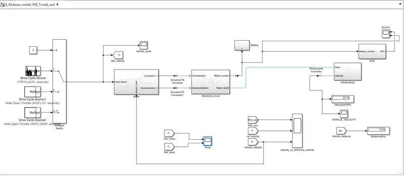
- We divide the model into several parts. input source
- Wheels and body
- Electrical system
- Battery system and SOC
- the controller
Wheels and Body:-
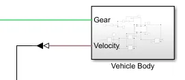
Body and wheel subsystems:
The above blocks form a subsystem as part of the whole vehicle. The three tires are connected, the two right tires are the rear wheels and the left tire is the front wheel. They are connected to the hubs of the body blocks. And their respective axes are connected accordingly. We are connecting the rear axle to the gears here because we want the model to be a rear wheel drive vehicle. Here, the Wind Speed section and the Angle of Climb port are connected to a block of physical constants that is kept at zero. 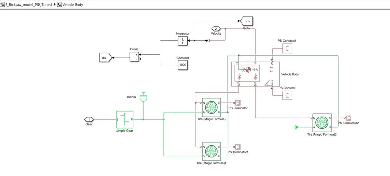
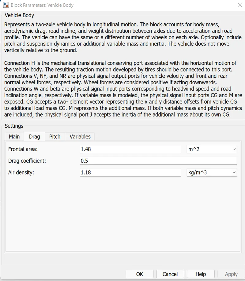
Vehicle Body:-

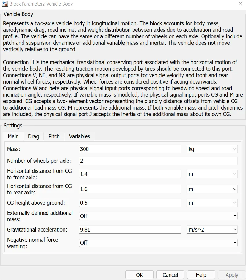
The body module represents a two-axle body with longitudinal movement. Vehicles can have the same or different number of wheels on each axle. For example, two wheels on the front axle and one wheel on the rear axle. Let's say the wheels are the same size. A vehicle may also have a center of gravity (CG) at or below the driving plane.
This unit takes into account body mass, air resistance, road slope and weight distribution between axles due to acceleration and road profile. Includes optional ride and suspension dynamics. The vehicle does not move vertically relative to the ground.
A block can optionally have externally determined masses and externally determined inertia. The body mass, inertia and center of gravity of the car may change as the system changes during the simulation.
This block has 6 ports that can be used to model different aspects of the car body. These sections are mentioned below.
- H stands for the hub used to attach the wheel hub to the vehicle body.
- V The physical signal output port representing the speed is used to output the vehicle speed. W physics signal port and allows us to model the wind speed acting on the vehicle.
- The physical NR signal output port is connected to the rear wheel. NF physical signal output port connected to the front wheel of the vehicle.
- A beta physical signal input port that allows the vehicle to withstand slopes with climbing forces
Tire (Magic Formula):-
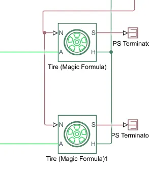
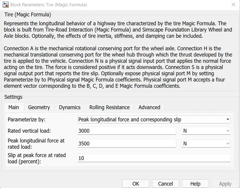
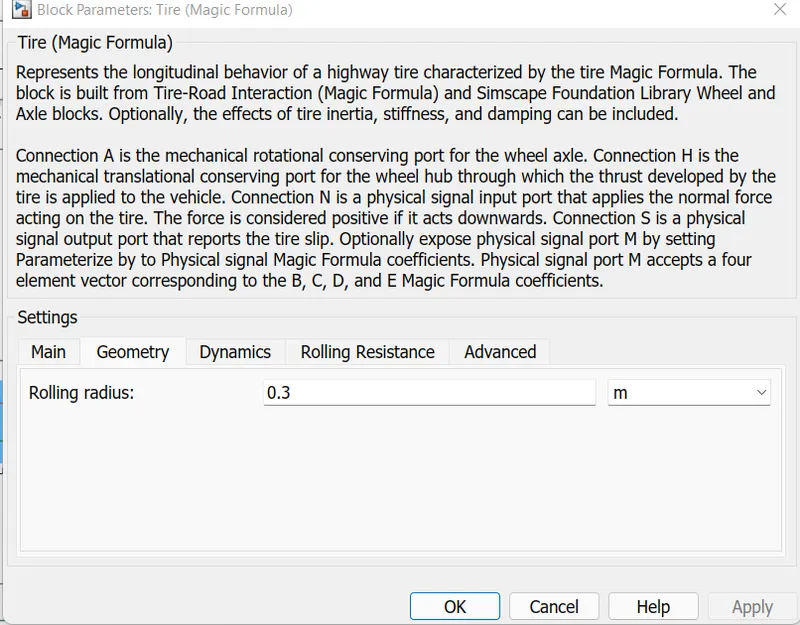
The tire block (Magic Formula) models a tire with longitudinal behavior defined by the Magic Formula [1], an empirical equation based on four fitted coefficients. This module can simulate tire dynamics under constant or changing road conditions.
As the tire rolls on the road, the longitudinal direction of the tire is the same as the direction of its movement. This block is a structural component based on the Tire Road Interaction (Magic Formula) block.
To increase the reliability of the tire model, you can specify properties such as tire compliance, inertia and rolling resistance. However, these properties increase the complexity of the tire model and slow down the simulation. If you are modeling the model in real-time or preparing the model for hardware-in-the-loop (HIL) simulation, consider ignoring tire compliance and inertia.
- Interface A is the mechanically rotating end of the shaft.
- Link H is a Thurst designed mechanical anti-rotation port on the hub.
- Connection N is the physical signal input port for applying the normal force acting on the deck.
- Connection S is the output port for the physical signal that reports tire slip.
Gears:-
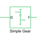
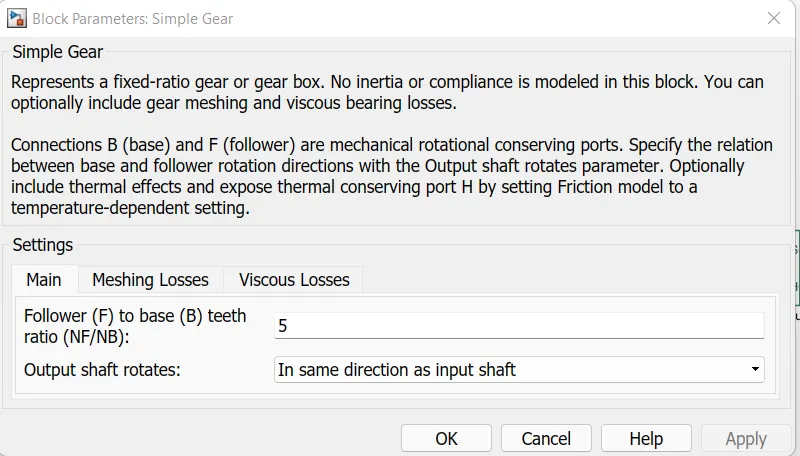
This module simulates a gear system with a fixed gear ratio and no inertia effects. However, we can modify the engagement of the gear teeth if the drive to base ratio is set to 2 and the output shaft rotates in the same direction as the input shaft. These modules form a subsystem as part of the whole vehicle. Four tires are connected, the two right tires are the front wheels and the two left tires are the rear wheels. They are connected to the vehicle through hub ports and the axles are connected accordingly. Here we connect the rear axle to the gears because we want the model to be a rear wheel drive vehicle.
Circuit Subsystem:-
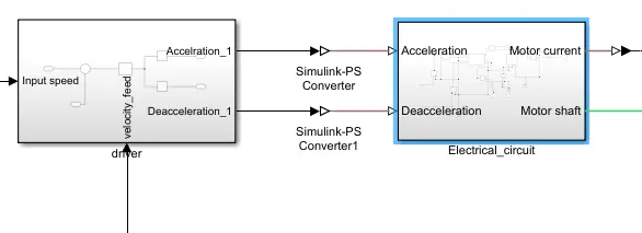
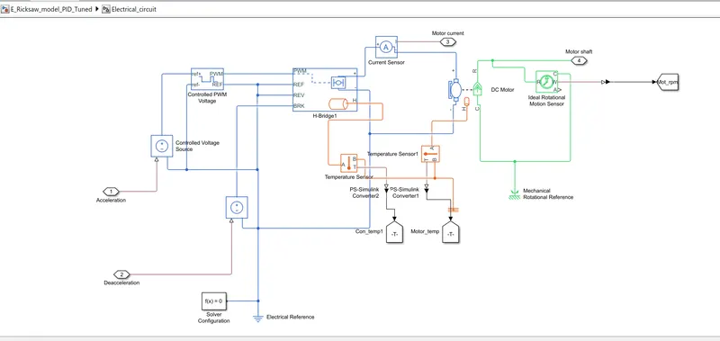
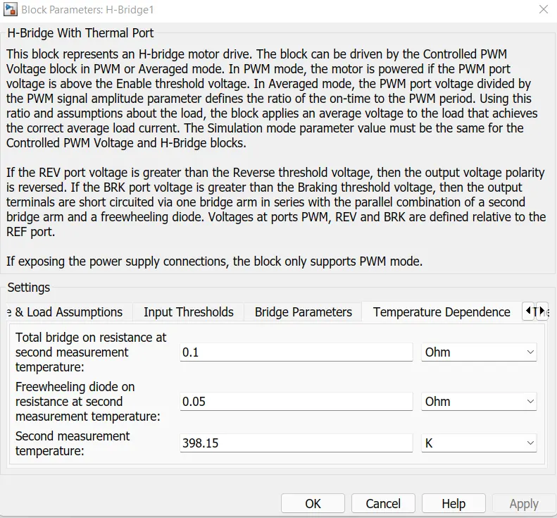
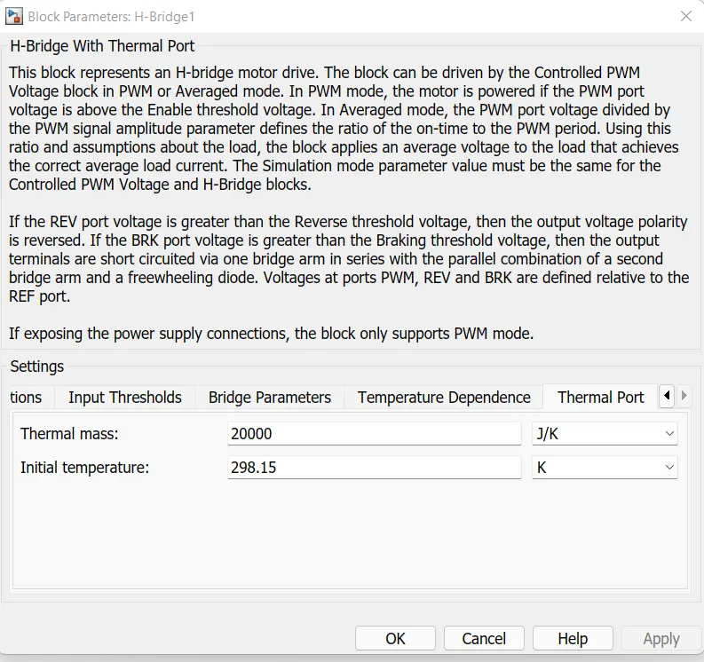
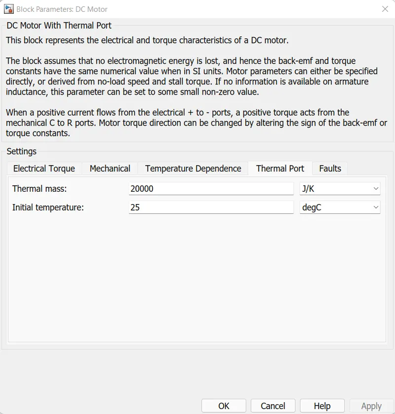
In the circuit subsystem, we have an H-bridge that is driven by the PWM controller method. Through this H bridge we supply current to the DC motor to control the speed and other parameters. We also have thermal gates on the H-bridge and DC motors to help determine their temperature during operation.
Controlled PWM Voltage:-
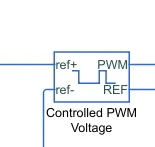
- Electrical Input Ports - The module calculates the duty cycle based on the reference voltage at its ref+ and refs. This modeling option is standard.
- PS Input - Directly input the duty cycle value through the physical input signal port.
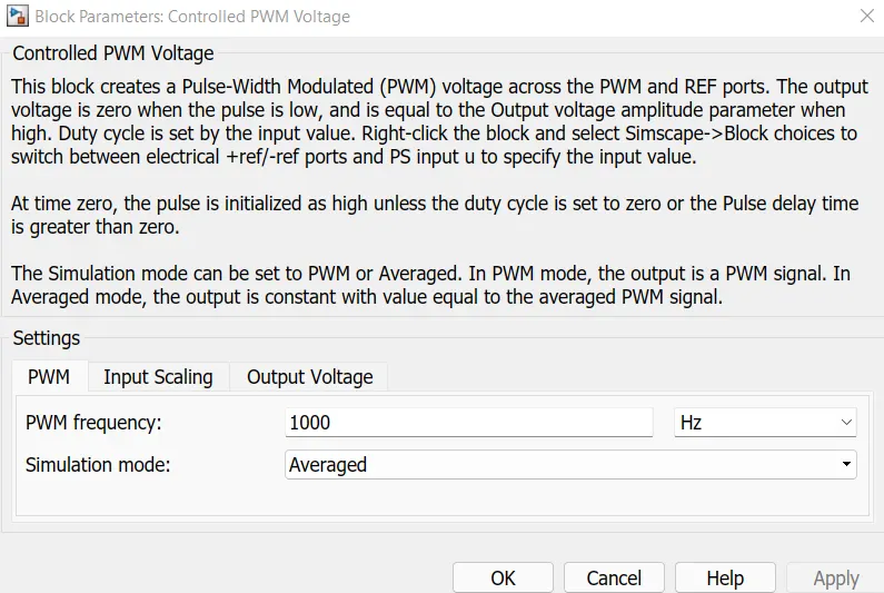
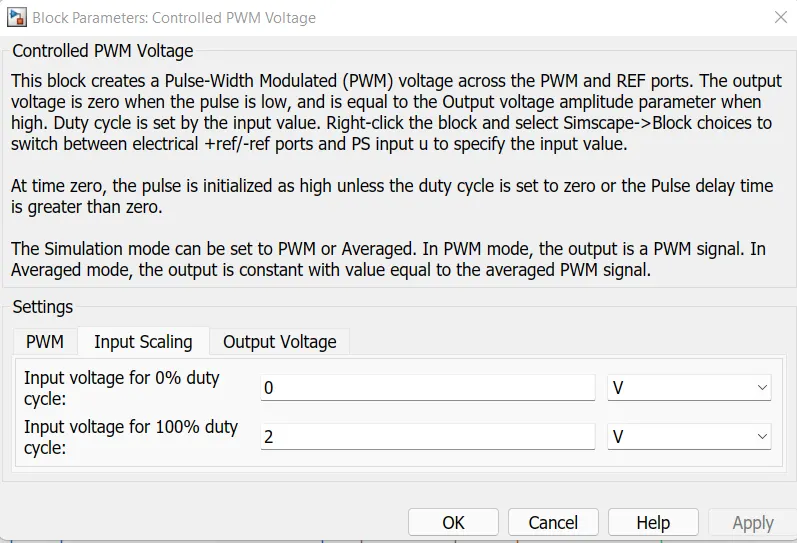
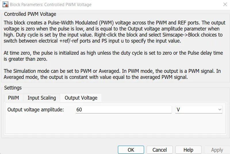
- Next I used a controlled PWM voltage to supply a controlled pulse width modulated voltage to the H bridge module. The voltage pulses generated by this unit depend on the duty cycle, which is the ratio of the time the switch is on to the time required for one cycle. The duty cycle formula is
Duty cycle: - ton/(ton+toff)
Ton/Tcyc, where Tcyc = time spent in one cycle
The required duty cycle for the electrical input port variant of the block is
100∗Vref−VminVmax−Vmin Percent
Where:
Vref is the reference voltage of the ref+ and ref-gates. Vmin is the minimum reference voltage.
Vmax is the maximum reference voltage. The value of the output voltage magnitude parameter determines the magnitude of the output voltage.
At zero, the pulse is initialized high unless the pulse delay time parameter is greater than zero or the required duty cycle is zero.
H-Bridge:-
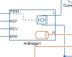
The H-bridge module is the H-bridge motor driver. The block has the following two simulation mode options:
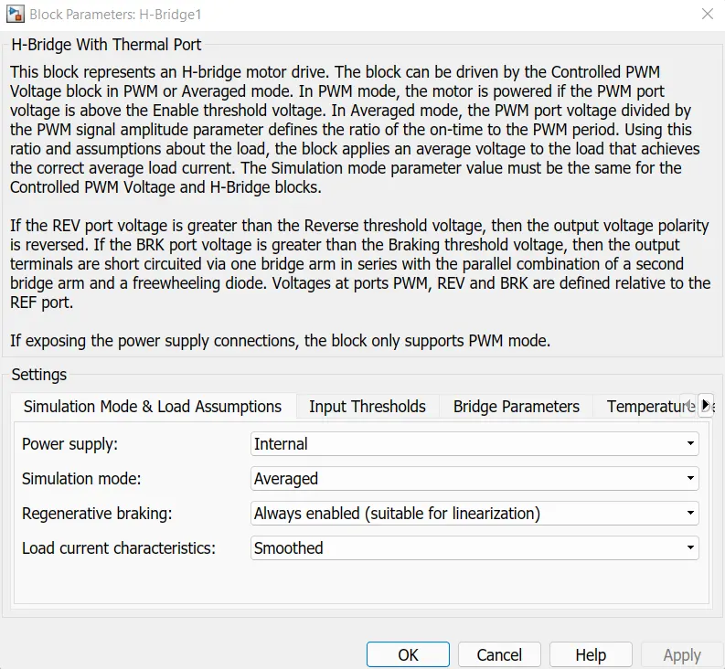
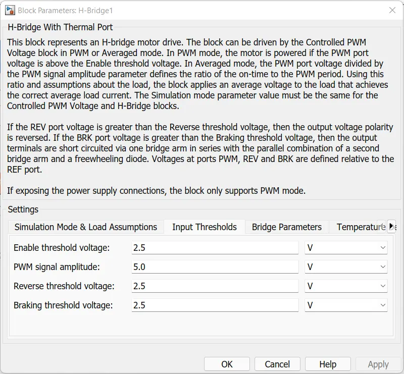
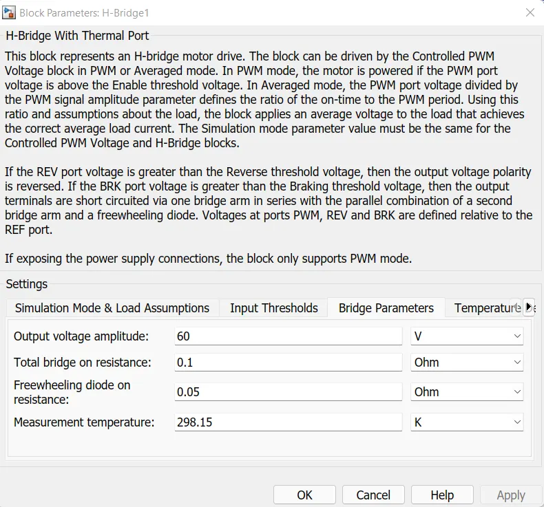
PWM - The output of the H-bridge module is a controlled voltage that depends on the input signal to the PWM port. If the value of the input signal is greater than the value of the activation threshold voltage parameter, the output of the H-bridge block is turned on, and its value is equal to the value of the output voltage amplitude parameter. If its value is less than the Enable Threshold Voltage value, the unit maintains the load circuit using one of the following three freewheeling modes:
If the PWM frequency is high enough. Synchronous operation with freewheel movement back to the source through the bridge arm also helps to equalize the current. In cases where the current is not smooth or may be discontinuous (ie it goes to zero between PWM cycles), use the Unsmoothed or Discontinuous option. This option must also specify the values of the total load series resistance, the total load series inductance, and the PWM frequency. During simulation, the block uses these values to calculate a more accurate H-bridge output voltage value, which provides the same average current as when simulating in PWM mode.
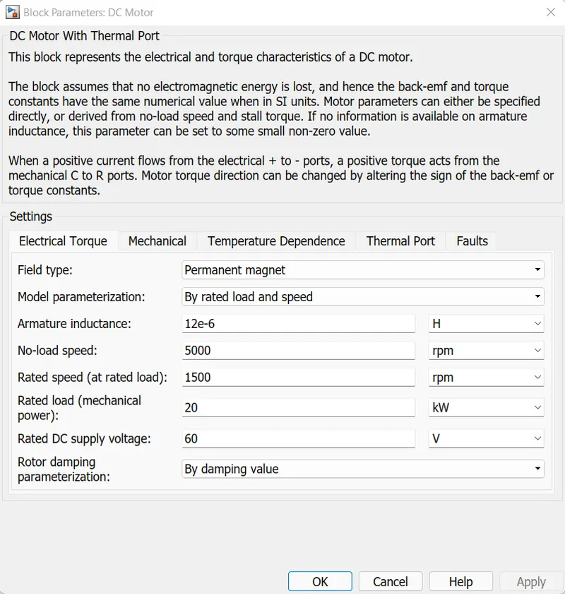
DC motor:
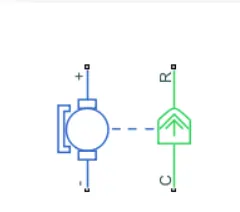
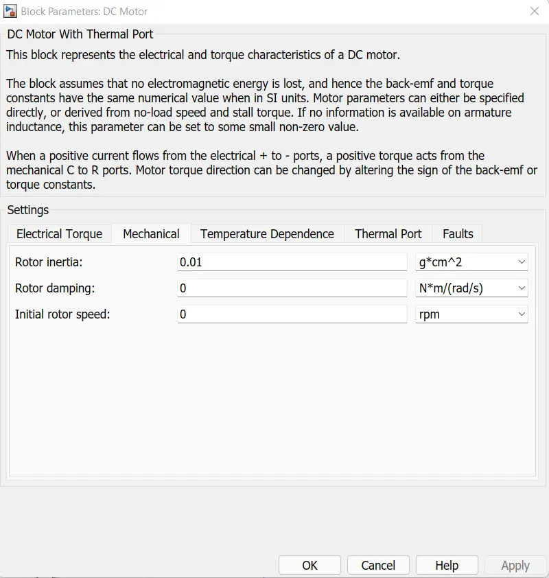
The DC motor block represents the electrical and torque characteristics of a DC motor using the following equivalent circuit model:
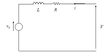
By setting the Model Parameter parameter to By Equivalent Circuit Parameters, you can specify the equivalent circuit parameters for this model. The resistance R corresponds to the resistance you specified in the armature resistance parameter. The inductor L corresponds to the inductance you specified in the armature inductance parameter.
You can specify how the DC motor's magnetic field is generated by setting the Field Type parameter to the desired setting. The permanent magnets in the motor induce the following back EMF vb in the armature:

where kv is the back-EMF constant and ω is the angular velocity. The motor produces the following torque, which is proportional to the motor current:
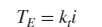
where kt is the torque constant. The DC motor module does not absorb any electromagnetic losses. This means that the mechanical effect is equal to the electrical effect given off by the back EMF of the armature. Make these two expressions equal:
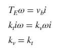
Therefore, you can specify kv or kt in the block parameters.
If the magnetic field is generated by the current flowing through the winding, the residual EMF constant depends on the field current If:
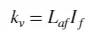
where Laf is the field armature mutual inductance. The torque and speed characteristics of the DC motor module are related to the parameters in the figure above. By setting the model parameter parameter to At Locking Torque and No Load Speed or At Rated Power, Rated Speed and Nanoload Speed, the block resolves the corresponding circuit parameters as follows:
A constant torque to speed ratio L has no effect. Sum the voltages around the loop and rearrange:
Temperature sensor:
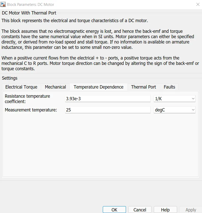
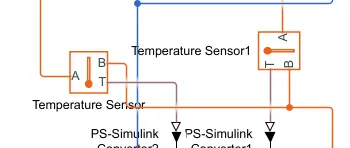
Use a thermal gate to simulate the effect of copper resistive losses, which convert electrical energy into heat. More information on using thermal gates and temperature dependence and thermal gate parameters. The thermal port T reports the temperature difference in the sensor. The measurement is positive if the temperature at port A is higher than the temperature at port B.
Battery System and SOC:
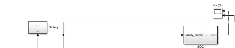
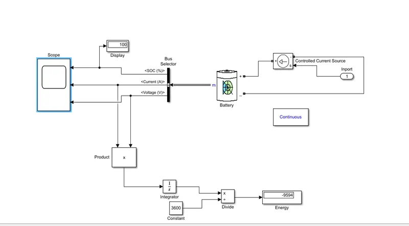
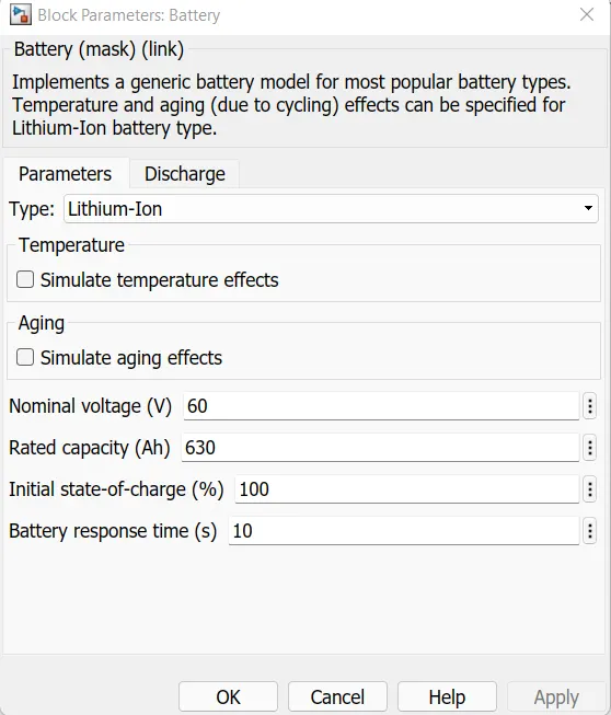
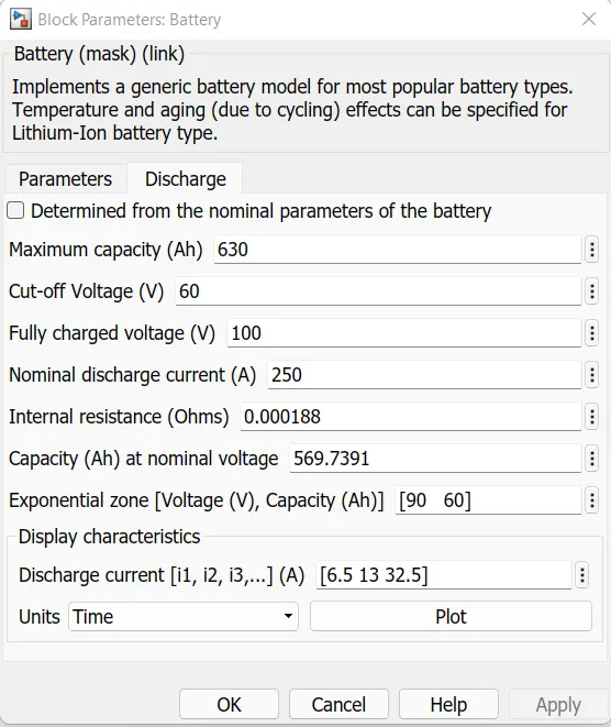
If motors and other equipment need power, we supply battery packs. This battery pack is determined by engine power and other electrical loads. That's why we used lithium-ion batteries. Introduces the general battery model, which is the most popular battery model.
State of Charge (SOC):
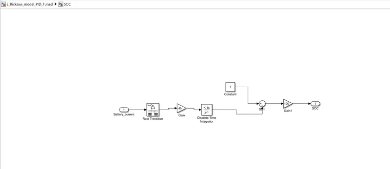
We used the following modules to calculate SOC.
- Rate transition: Handles data transfer between different speeds and tasks.
- Gain: - cell or matrix amplification at 60 V battery voltage. So my formula is like 1/(60*3600).
- Discrete-time integrator: Discrete-time integrator or summation of input signals.
Port and Source Model:
We have a multi-port switch and use three types of driving cycles to calculate battery power, motor and inverter temperature, etc. differently. Here we develop a model of the motor supply source.
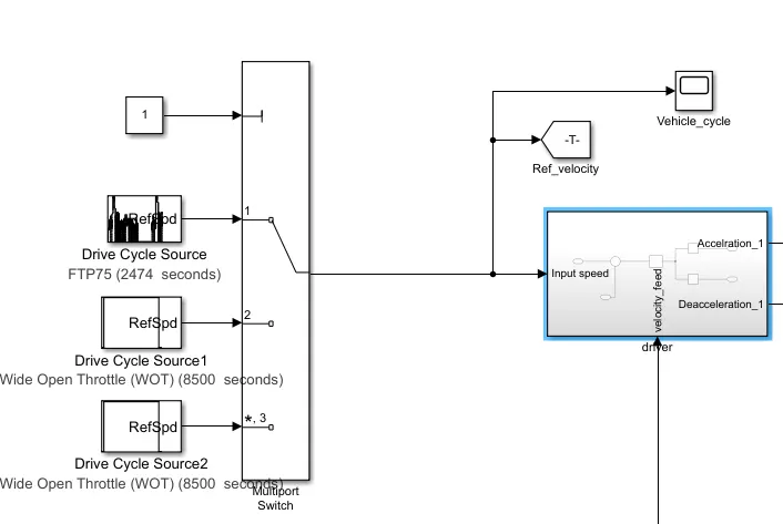
here we have deigned the source model for the feeding of the motor.
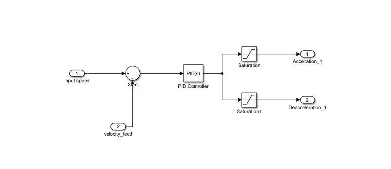
PID controller:
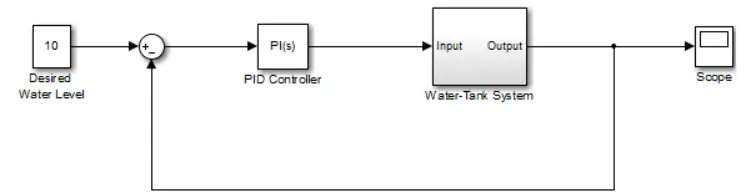
The PID controller block implements a PID controller (PID only, PI, PD, P or I only). This block is identical to a discrete PID controller block with the time domain parameter set to continuous time.
The output of the block is the weighted sum of the input signal, the integral of the input signal, and the derivative of the input signal. Weights are proportional, integral and derivative gain parameters. First-order pole-filtered derivative effect.
The block supports different controller types and structures. Configurable options in the block include:
- Controller type (PID, PI, PD, P or I only) - see controller parameters.
- Shape of the controller (parallel or ideal) - see the Shape parameter.
- Time Domain (Continuous or Discrete) - See time domain parameters.
- Initial conditions and reset triggers - See source and external reset parameters.
- Output winding limit and built-in anti-conduction mechanism - see Limit Output parameters. Signal tracing for non-uniform control transfer and multi-loop control - see Enabling the Trace Mode parameter.
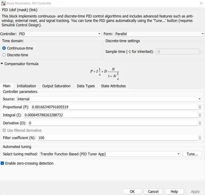
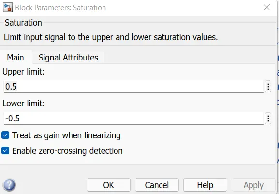
Saturation:
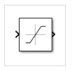
The saturation block produces an output signal that is the value of the input signal bounded by upper and lower saturation values. Upper and lower limits are determined by Upper limit and Lower limit parameters.
Case: We will use the model in three different classes
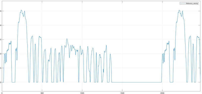
Case 1: We will first run the model through an FTP75 loop for 2475 seconds to see how all the parameters behave when setting the PID.
Case 2: Second, we will test the model using a WOT cycle of 75 seconds to see how the tuned PID parameters behave.
Case 3: Finally, we will do a WOT cycle and maintain 100 km at 45 km/h to see the behavior of the set PID parameters.
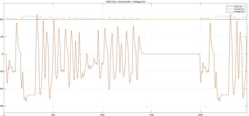
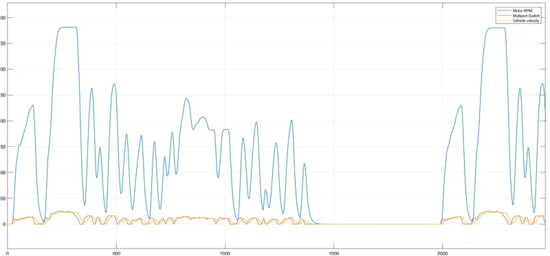
Case 1: We will first run the model through an FTP75 loop for 2475 seconds to see how all the parameters behave when setting the PID.
Reference speed:-
Battery SOC, Current % Voltage: -
Battery SOC and Motor Current:-
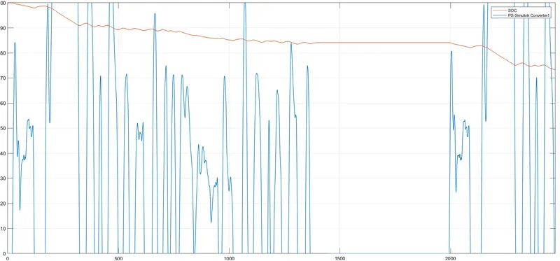
System SOC is 75%.
Motor speed vs. vehicle speed vs. reference speed:-
Motor and inverter temperature:
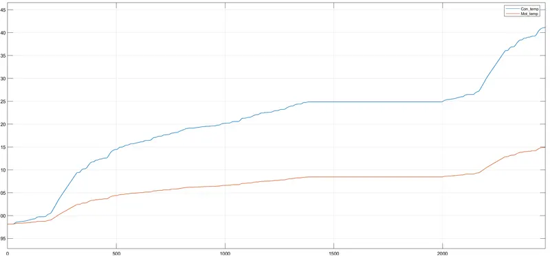
The inverter temperature is higher than the motor temperature.
The converter temperature is 298-342K and the engine temperature is 298-315K.
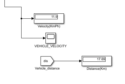
Based on this driving cycle, the distance is 17.69 km and the speed is 11.9 km/h.
Case 2: Second, we will test the model using a WOT cycle of 75 seconds to see how the tuned PID parameters behave. Reference speed:-
Battery SOC, Current and Voltage:-
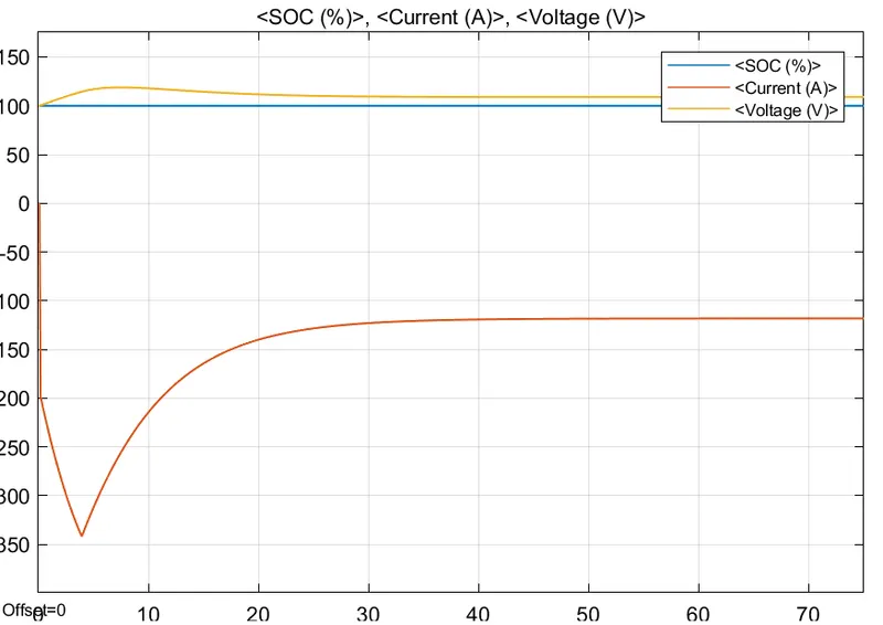
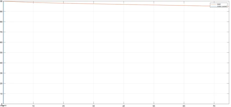
SOC and Motor Current:
SOC for this driving cycle is 95%.
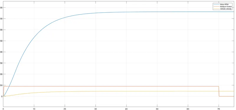
Motor speed vs. reference speed vs. vehicle speed:
Motor Temperature and Inverter Temperature:
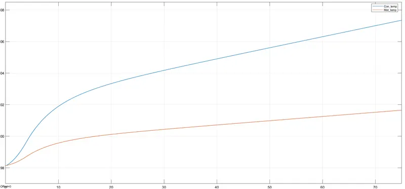
Based on this drive cycle, the inverter temperature is 298-307K and the motor temperature is 298-301K. The distance traveled is 1.514 km at a speed of 22.74 km/h.
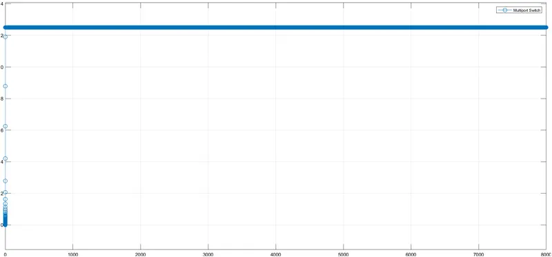
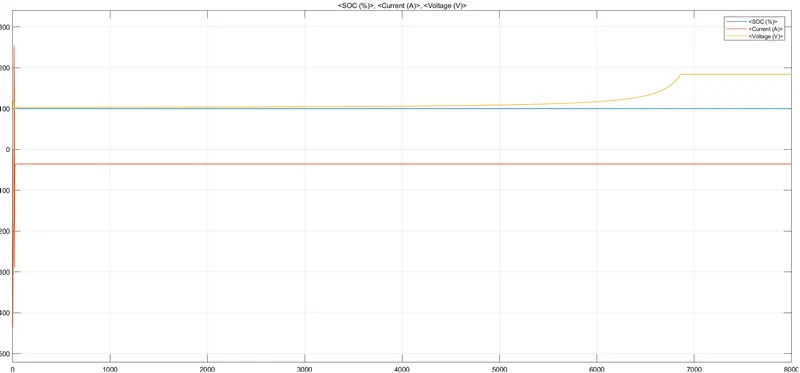
Case 3: Finally, we will do a WOT cycle and maintain 100 km at 45 km/h to see the behavior of the set PID parameters.
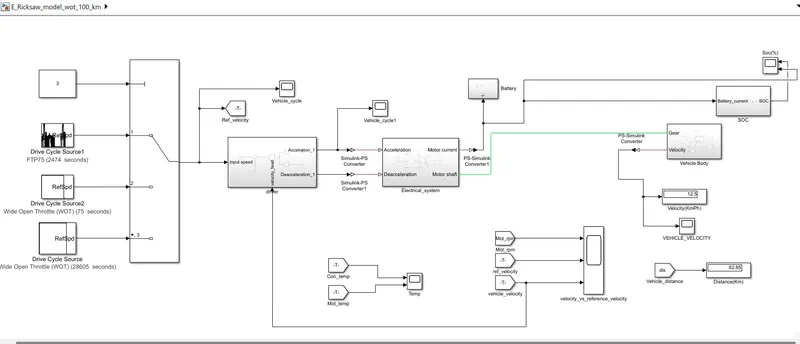
Reference speed:
Battery SOC, Current and Voltage:
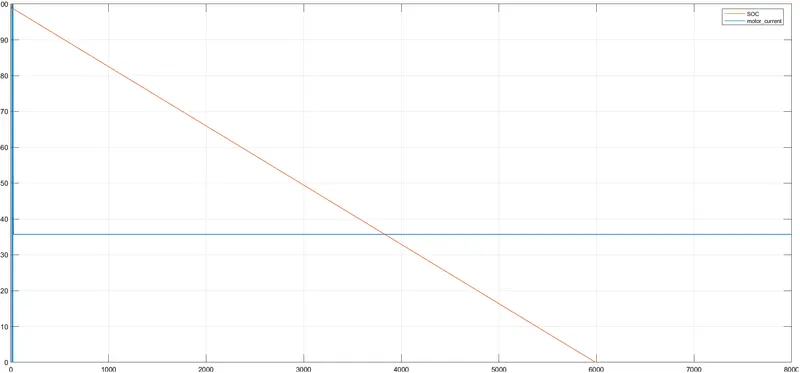
SOC and Motor Current:
According to the graph, we can see that our SOC goes to zero, which means that the battery is completely discharged. Therefore, we need a high rated battery capacity to drive this model for 100 km at 45 km/h as the target.
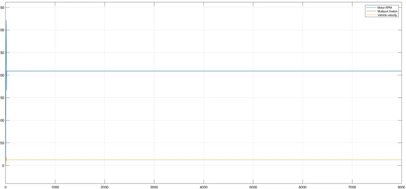
Motor speed vs. reference speed vs. vehicle speed:
Motor Temperature and Inverter Temperature:-
Our nominal temperature is 298K, so the motor temperature rises to 355K and the inverter temperature rises to 322K.
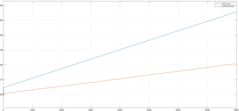
According to this display we have a speed of 12.5 m/s and a distance of 100 km.
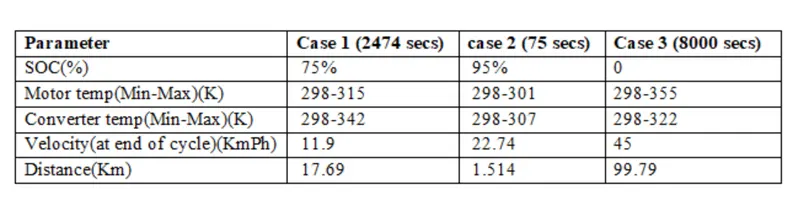
Conclusion: Depending on the objective, we tested three driveless cycles to test the behavior of the blocks and components at each level. And we've decided that for acceleration and deceleration we save some energy for future use, but if we need the system to get energy continuously, we need to increase the battery capacity.
As you can see in the third case, we have to drive 100 km at a speed of 45 km/h and then our SOC goes to zero at the end of the cycle. This is because our energy consumption is constant. There's nothing like slow mode, and our regenerative mode keeps the battery running.