Final Project: Electric Rickshaw modelling
Introduction :
And electric vehicle is a vehicle that uses electric motors for propulsion. This type of vehicles use electricity instead of fuels. Because of this, electrical vehicles do not produce any exhaust gases or pollution.
Components used in simulation of an electric rickshaw :
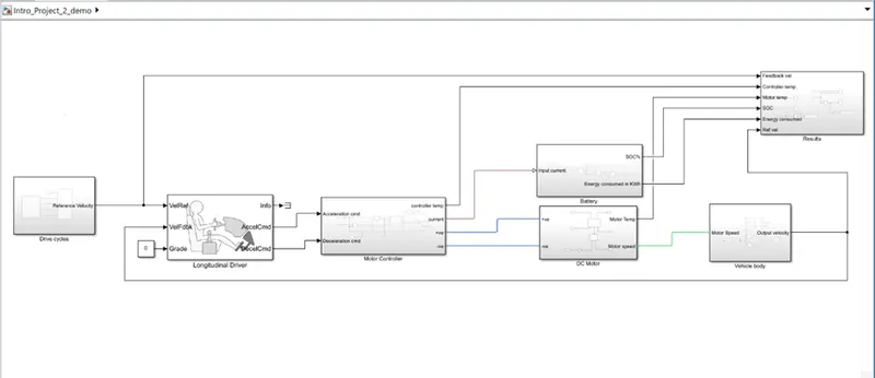
1.Drive cycle
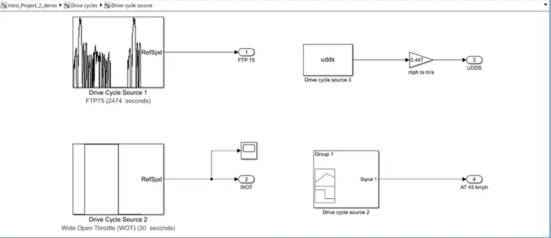
A drive cycle is a series of data points representing speed of vehicle versus time.
I considered 4 drive cycles in which 3 are standard (FTP 75,WOT, UDDS) and 1 is made by me to make the vehicle run at constant speed at 45 kmph. For UDDS the speed is in mph so I used a gain block and converted it into m/s.
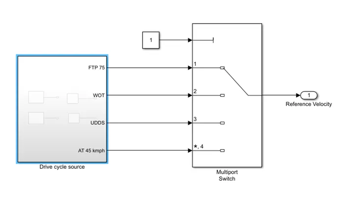
As per our simulation we can choose the drive cycle using a multiport switch.
2.Longitudinal Driver
This is an inbuilt block provided by the power train block set.
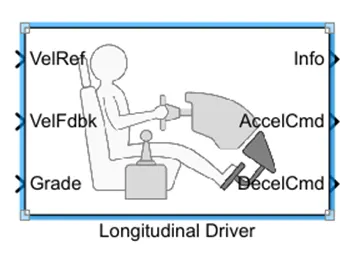
The VelRef port is reference velocity port where the input drive cycle data is fed.
VelFdbk port corresponding to the feedback velocity. The actual velocity output given by the vehicle body is connected here. By comparing the feedback velocity with the reference velocity, the driver block generates acceleration and breaking signals.
Grade corresponds to the great angle in the simulation. We consider grade angle as zero.
Info gives the output for the bus signal for different block calculations like difference in reference, vehicle speed and vehicle speed etc.
Accelcmd & Decelcmd are the acceleration and deceleration. Commands generated respectively. These are connected to the corresponding parts of the control PWM voltage block.
Hear the selected controller type is PI.
3.Motor controller
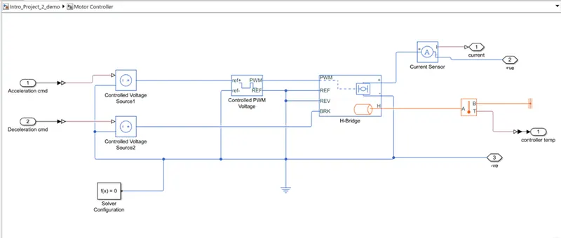
H bridge block along with inbuilt PWM block, together considered as a motor controller
H – bridge
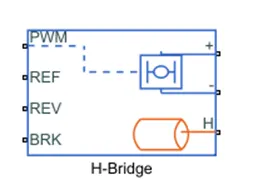
This block represents an H Bridge motor drive. The block can be driven by controlled PWM voltage block in PWM or averaged mode.
In PWM mode, the motor is powered if the PWM port voltage is above the enabled threshold voltage.
In averaged mode, the PWM port voltage divided by PWM signal amplitude parameter defines the ratio of the on time to the PWM period.
Here PWM is connected to the PWM block (pulse input).
REF is for the reference input. This is combined with PWM reference. Here references input is connected to the electrical reference.
REV corresponds to the reverse motion of the vehicle. This port is connected to the electrical reference.
BRK is for the braking of the vehicle.
H port is thermal port. We can measure the temperature change through this port by using a temperature sensor.
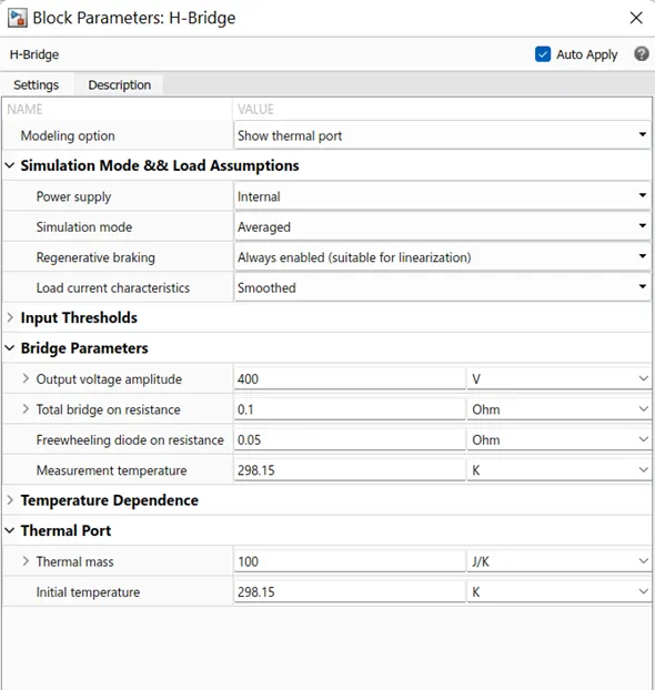
Parameters of H bridge
PWM block
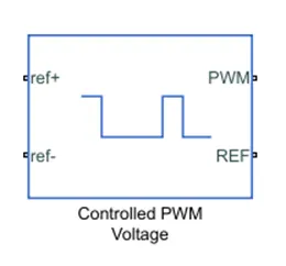
This block is used for providing the proper pulse input to the H bridge circuit.
Pwm and REF connections are for the corresponding ports on the H Bridge circuit.
The 2 reference inputs correspond to the throttle input given by the driver. The block generates corresponding pulse width as per the acceleration and brakes applied by the driver himself.
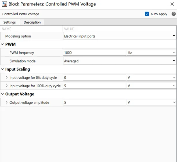
Parameters of PWM
4.DC Motor subsystem
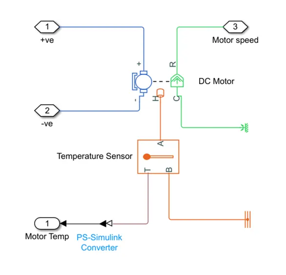
Dc motor
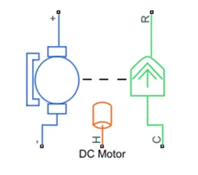
This is the DC motor which would give the rotational power to the wheels. The DC motor terminals are connected as
+ve to the +ve electrical signal
-ve to the -ve electrical signal
R port is the rotational output of the motor
C is the casing of motor and is connected to the mechanical rotational reference
H port is thermal port. We can measure the temperature change through this port by using a temperature sensor.
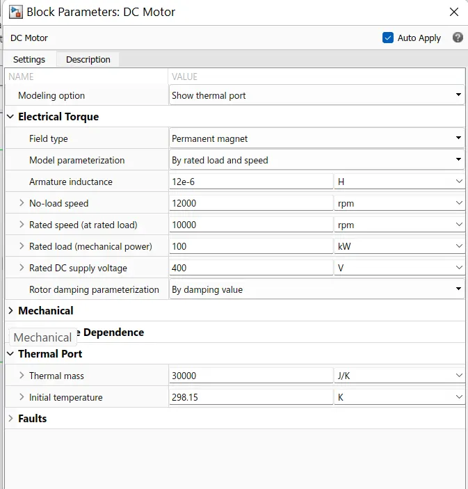
Parameters of DC motor
Temperature sensor
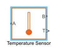
This block measures temperature in a thermal network. There is no heat flow through the sensor. The physical signal port T reports the temperature difference across the sensor. The measurement is positive when the temperature at port A is greater than the temperature at port B.
To measure the temperature of motor A port is connected to motor and B port is connected to reference. This block is block is used in controller subsystem also to measure the temperature of controller.
5.Battery subsystem
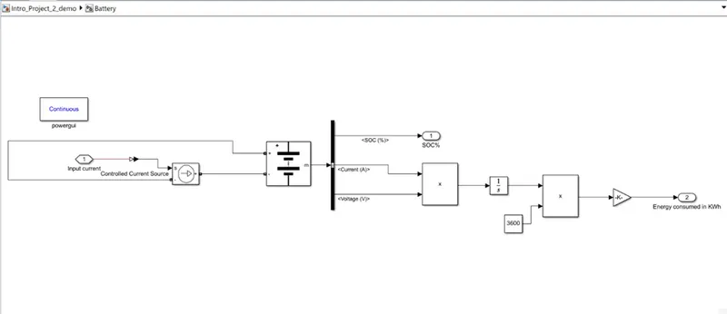
Battery
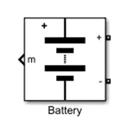
Battery is a device that stores chemical energy and convert it into electrical energy. The chemical reaction in a battery involves the flow of electrons from one electrode to another through and external circuit. The flow of electrons provides an electric current that can be used to do work.
This block is used to find SOC and energy consumption.
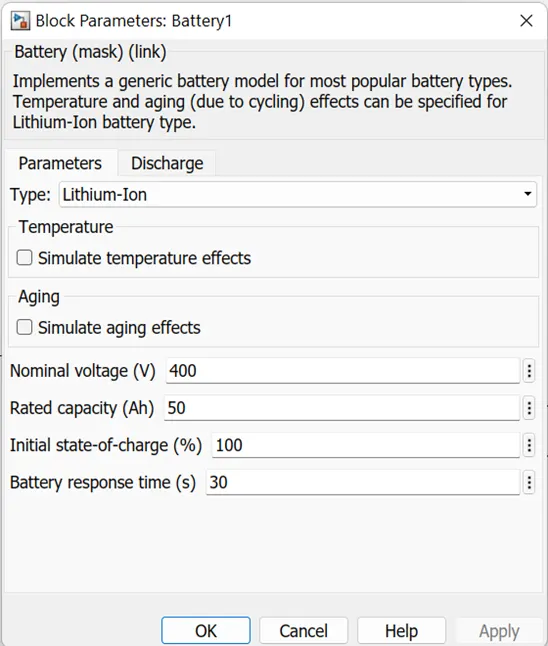
Parameters of Battery
6.Vehicle Body Subsystem
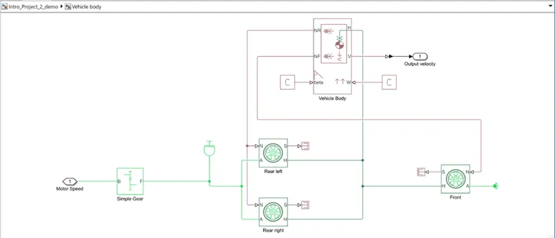
This represents a 2 axle vehicle body in motion. This accounts for body mass, aerodynamic drag grade and centre of gravity of the vehicle body.
Vehicle body
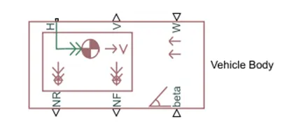
Input ports
W – wind velocity
Beta – grade angle
Output ports
V – velocity in m/s
NF - Normal force on front axle
NR – Normal force on rear axle
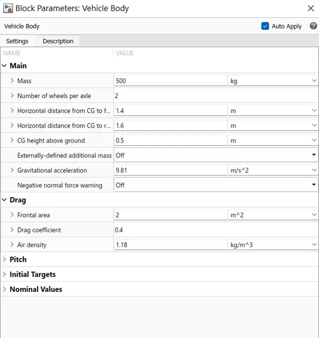
Vehicle body parameters are taken as default
Vehicle body parameters
Tires
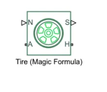
Input ports
N – Normal force acting on tire
Output ports
S – Slip related to tire and contact surface
Conserving ports
H – Represents wheel hub
A – Represents alxe
Gear
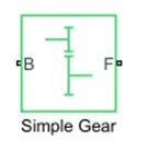
Represents a fixed-ratio gear or gear box. Connections B and F are mechanical rotational conserving ports.
B – Port associated with input shaft
F – Port associated with output shaft
Results
A separate subsystem is created to observe all the results at one place
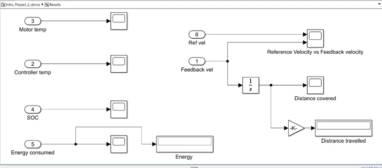
For FTP 75 Drive cycle
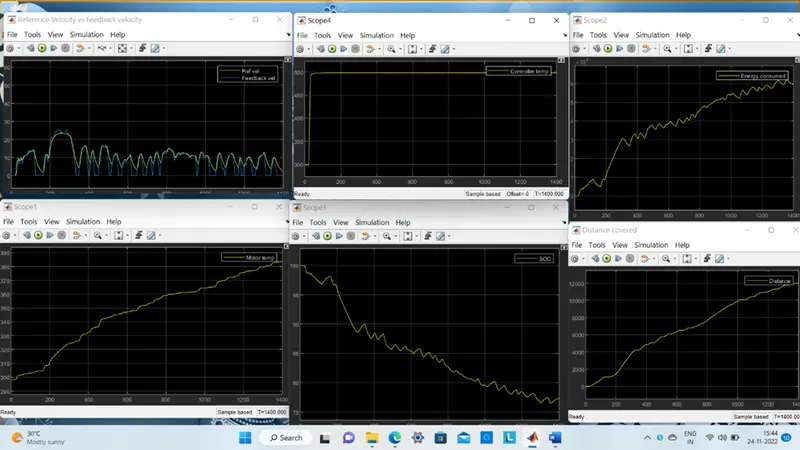
- The actual speed is approximately followed the 75% of reference drive cycle.
- The temperature of the motor is increased to 354.5 K.
- The temperature of the controller is increased to 321 K.
- The SOC of battery is reduced to 58%.
- By running the vehicle with this drive for 2474 sec, the distance travelled is about 17.7 km.
For WOT Drive cycle
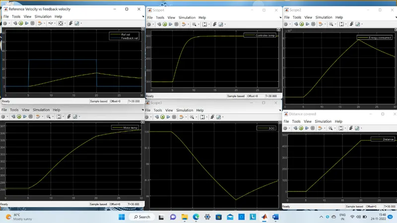
- The actual speed is not followed the reference drive cycle because the motor and battery capacity considered by me is not able to propel the required speed in that time line.
- The temperature of the motor is increased to 302.8 K.
- The temperature of the controller is increased to 300.2 K.
- The SOC of battery is reduced to 98.3%.
- By running the vehicle with this drive for 30 sec, the distance travelled is about 0.44 km.
For UDDS Drive cycle
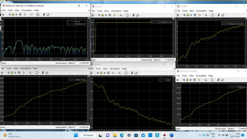
- The actual speed is approximately followed the 70 % of reference drive cycle.
- The temperature of the motor is increased to 331.9 K.
- The temperature of the controller is increased to 312.4 K.
- The SOC of battery is reduced to 73 %.
- By running the vehicle with this drive for 1400 sec, the distance travelled is about 11.98 km.
For manually prepared drive cycle
(To run at constant speed 45 kmph)
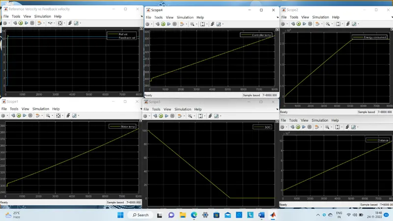
- The actual speed is approximately followed the 96% of reference drive cycle.
- The temperature of the motor is increased to 387.7 K.
- The temperature of the controller is increased to 332.2 K
- By running the vehicle with this drive for 8200 sec, the distance travelled is about 101 km.