Final Project: Electric Rickshaw modelling
Aim:
Create a detailed MATLAB model of an electric rickshaw (three wheel passenger vehicle) as per details below:
- Rear wheels driven by PM brushed type motor
- Assume efficiency points of motor controller and motor
- Make an excel sheet of all input and assumed data
Objective:
* In this project, we are going to bild the MATLAB model of the E-Rickshaw using a PM brushed type DC motor.
* We come to know what is E-Rickshaw and how it works and the benefits of this vehicle.
* Then we make an E-Rickshaw by using MATLAB and SIMULINK software.
Description:
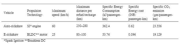
* E-Rickshaws have been becoming more popular in some cities since 2008, which is meant for an alternative to the auto-rickshaws because of their low fuel cost.
* They are widely accepted as an alternative to the petrol, diesel and CNG. They are powered with electric motor having 650-1400 watts.
* They are mostly used in India and China.
Design and Construction:
* Made of Mild steel tubular chassis, consisting three wheel s with differential mechanism on rear wheels.
* Motor is brushless DC motor.
* The electrical version in india is 48V, while in Bangaladesh is 60V.
* The body design is mostly made up of thin sheets of aluminium or iron sheets.
* They are sold on basis of voltage supplied, and current output, and also number of MOFSET(metal oxide field effect transistors)
* The battery used is lead-acid battery with life of 6-12 months.
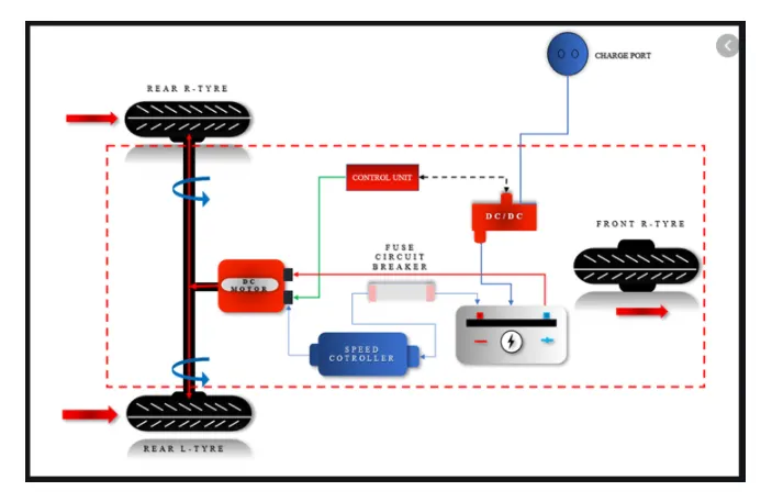
Basic Design of e-rickshaw:
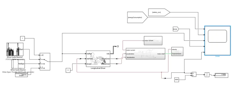
Simulink Model:
Initially, the current flows to DC motor from the battery through the DC-DC power converter to drive the motor. The Voltage is controlled by the controller. Then the power is transmitted to the wheels through the gearbox and controller will take the vehicle speed.
Model parameters:
i) Drive Cycle:
It is assumed as the input of the vehicle from the driver.
It is replaced how the driver drives the vehicle.
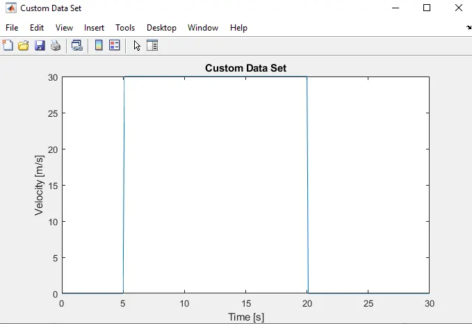
Here, three drive cycles are used to test the vehicle's performances, having high speed, low speed and braking conditions in it.
In this model, FTP 75, Wide Open Throttle and manually prepared drive cycle has been prepared.
FTP 75:
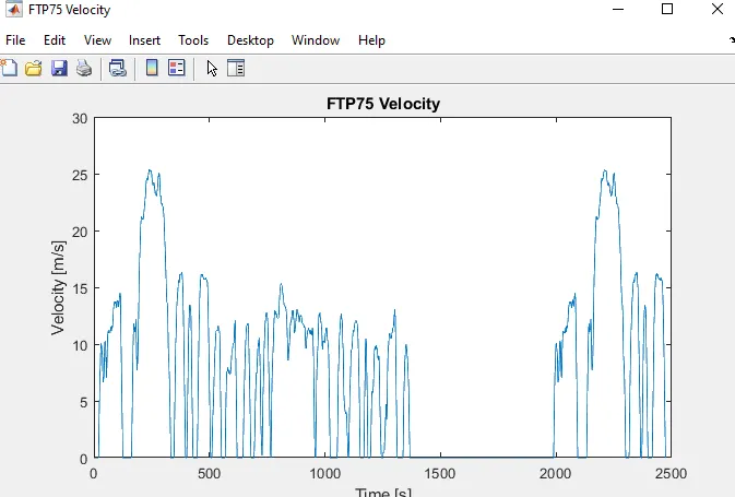
* It generates Standard or user defined longitudinal drive cycle. This output is the vehicle's longitudinal speed. It can be imported from Predefined sources, Workspace variables, .mat, .txt, .xls files.
Wide Open Throttle:
Manually Prepared Drive Cycle:
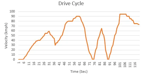
All the three drive cycles are controlled by the controller provided above the Constant through multi-port switch.
Driver Controller:
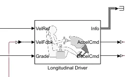
A speed tracking controller for generating normalized acceleration and braking commands based on reference and feedback velocities.
Use the external actions to input signals that can disable,hold,or override the close loop commands based on reference and feedback velocities.
Drive cycle is connected to a longitudinal driver, having six ports namely Velocity reference, vehicle feedback,grade,info,acceleration,deceleration.
Vehicle reference is given by drive cycle data and Vehicle feedback is given by the output of the motor. These two woll get the comparision of acceleration and deceleration output given to the motor controller. Accelerator command is given the PWM generator block and deceleration command is given to the regenerative braking. This block helps to generate the driver's conditions using the driver cycle block.
Motor and Controller:
i) DC Motor:
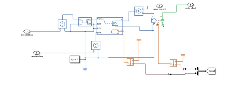
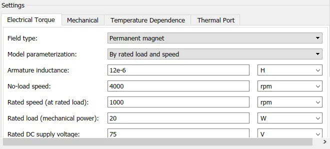
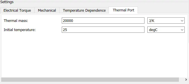
This block represents the electrical torque characteristics of the DC motor, that includes Thermal port to sense the temperature of the motor.
This block assumes that no electromagnetic energy is lost hence the back emf and torque constants have the same numerical value in SI units.
If No information is available on the armature, this parameter can be set into some small zero value.
Motor Controller:
The motor controller will get the input from the longitudinal driver. Its tasks are to control the speed of the motor according to the input of the driver.
Input1 gets from the accelcmd of the longitudinal driver and it is given to the controlled voltage source block. Controlled PWM Voltage will generate the PWM signal in such a way that H-bridge generate the voltage to DC motor for the given driver input.
All these components are the simscape electrical components so they need a connection to the solver configuration block that helps to solve the simulation.
Controlled PWM Source:
This Block creates a Pulse width modulated voltage across PWM and REF ports. The output Voltage is zero when the pulse is low, and is equal to the Output Voltage amplitude parameter is high, and is equal to the Output Voltage amplitude parameter when high. Duty cycle is set by the input value.
At the time zero, the pulse is initialized as high unless the duty cycle is set to zero or Pulse delay time is greater than zero.
Select simulation Mode as averaged.
Power Converter:
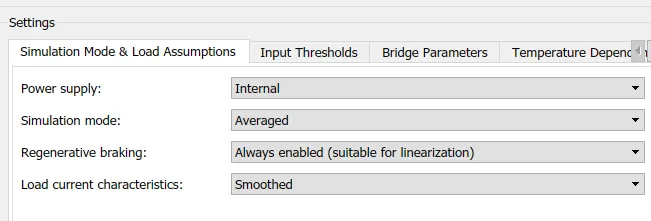
This block represents the H-Bridge motor drive. The block can be driven by the controlled voltage block in PWM or Averaged more.
In PWM mode, the motor is powered if the PWM port voltage is above enabled threshold voltage.
In Averaged mode, The PWM port voltage is divided by the PWM signal amplitude parameter defines the ratio of the on-time to the PWM period. The simulation mode parameter value must be the same for controlled PWM voltage and H-bridge blocks.
Temperature Sensor:
Used to measure the temperature of the H-bridge and Motor.
The physical port T reports the temperature difference across the sensor.
The Measurement is Positive when the temperature at A is Greater than at B.
Solver Configuration:
Defines Solver settings for simulation.
Electrical Reference:
Used to ground all electrical connections.
Thermal Reference:
Used to ground all the thermal connections.
Mechanical Reference:
Used to ground all the mechanical parts.
Battery:
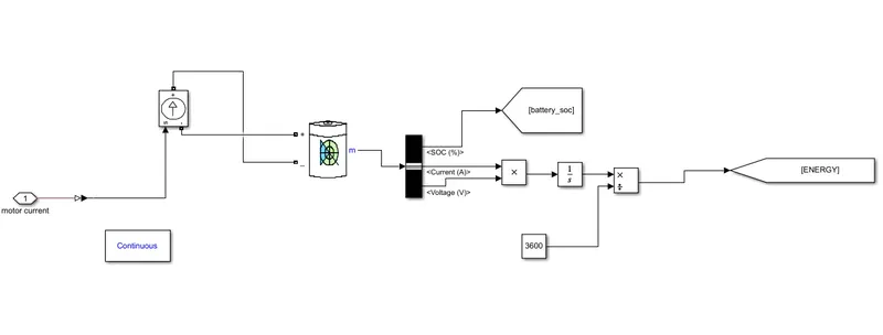
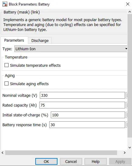
The Nominal voltage of the battery is 330V.
Initial SOC of battery is 100%
The battery has a positive and negative terminal which is given the voltage controlled source where the battery consumption is controlled by the motor controller and given to SOC block.
State of Charge is the percentage of the battery level presents after certain travel or consumption of the battery charge by the vehicle.
In this designed vehicle, the battery charge or SOC is calculated by giving it to the rate transitionand then to gain where 1/(nominal battery capacity) then to a discrete time integrator and it will get minus as it is considered to 100% and is multiplied with 100 to get the percentage of the battery.
The majority of the blocks are simscape blocks where physical to simulink converter is used to convert the physical signal from simscape block to simulink signal.
Vehicle Body and transmission:
Motor will produce the rotational output which will give to the transmission system.
The rotational output is taken by gear and to maintain the constant speed throroughout the transmission without any loss in speed from the motor to the tires.
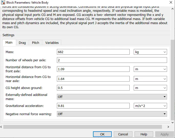
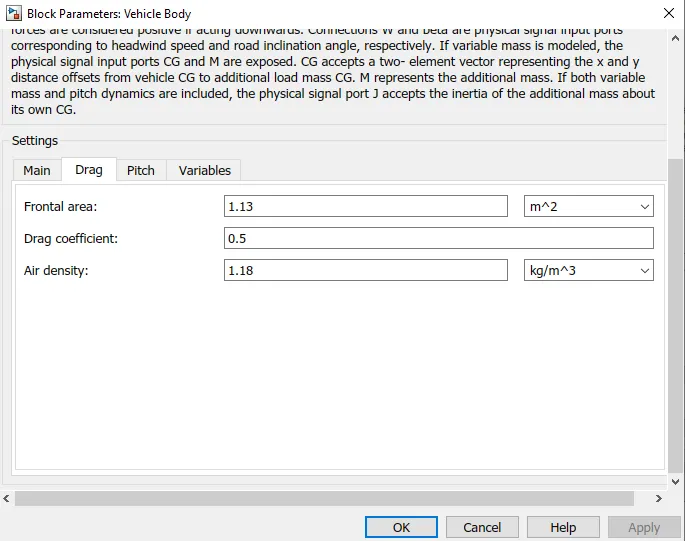
The Vehicle body is given below and how it inside the vehicle body and transmission system in the main design.
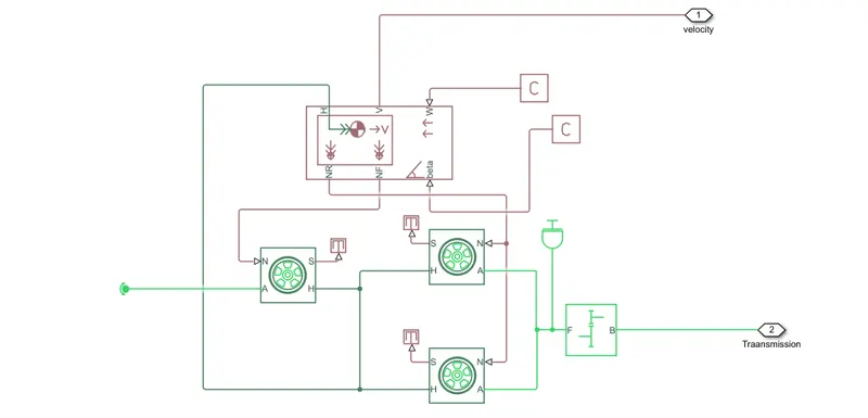
The Gear output is given to the axles of the rear wheels and it is shown that the gear is connected to the rear wheels and the front tire is free to rotational motion, ths the vehicle moves forward.
N is the normal force caused by the tires and it is given to the vehicle body in the normal port.
The body has an hub, Tire slip, Normal force and Axle connection, Wind velocity and imclination angle.
The tire hub is connected to the commpn node of the body.
The wid velocity is connected to a constant block and beta inclination angle is connected to the another constant block,where it is assigned to the wind velocity and inclinatin angle as per requirement.
Velocity is the output port where we can get the speed of the vehicle moving.
Tire represents the longitudinal behaviour of the highway tire characterized by Magic formula. The block is built from tire-road interaction. Optionally, he effects of the tire, inertia,stiffness,damping can be included.
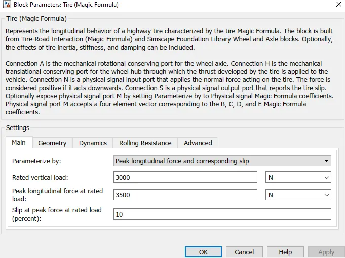
Inertia has one mechanical conserving port, the block positive direction is from port to the reference point. This means the inertia torque is positive if the inertia is accelerated in positive direction.
Gear box consists of no-inertia or any compilance given. We can optionally include gear meshing and viscous bearing losses.
Output shaft rotates in the same direction of the input shaft.
Base is connected to the Motor and the Follower is connected to the rear-wheel drive.
Scope Results:
i) For FTP75 Drive Cycle:
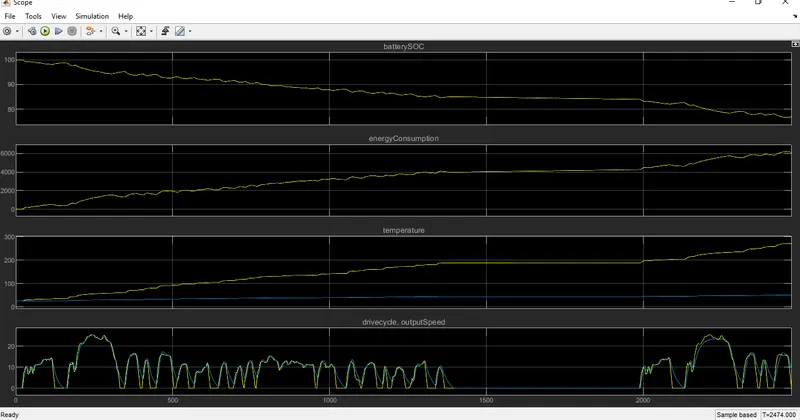
The actual speed is approximately followed the 90% of reference cycle.
Energy consumed by the battery is about 4000Wh at end of the cycle.
The SOC of the battery has been reduced to 78% approx.
The temperature of the motor and controller is about 270°C and 60°C
ii) Using WOT:
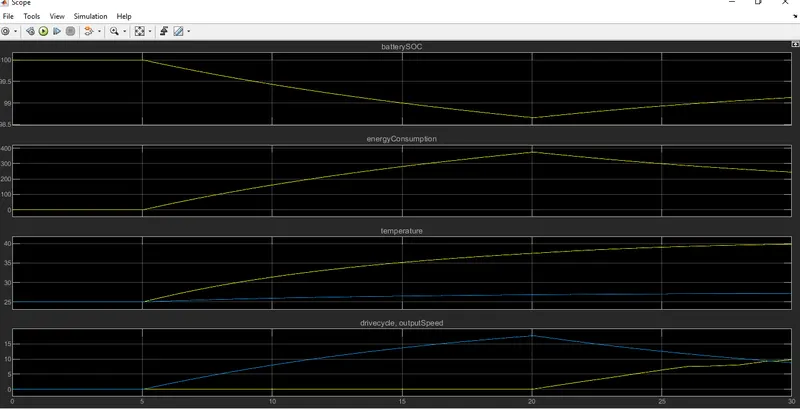
Energy consumed by the battery increases by 20 seconds and reduced gradually due to Back EMF and increases gradually to 300Wh.
The SOC of the battery has been reduced to 78% approx.
The temperature of the motor and controller is about 270°C and 60°C
Manually Prepared Cycle:
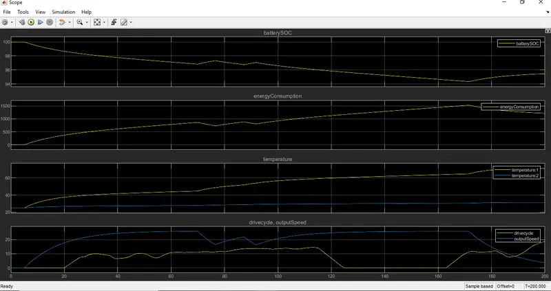 The actual path of the speed is approximately followed the reference of the Drive cycle.
Energy consumed by the battery is about ranging till 2000Wh.
The SOC of the battery is reduced to 92% approximately.
The temperature of the motor and controller is about 100 and 80 degree celsius.
Conclusion:
The MATLAB model of an electric rickshaw (three wheel passenger vehicle) has been created with the given Requirements using MATLAB and Simulink Software.