Final Project: Electric Rickshaw modelling
Create a detailed MATLAB model of an electric rickshaw (three-wheel passenger vehicle) as per details below:
Rear wheels driven by PM brushed type motor
Assume efficiency points of motor controller and motor
Make an excel sheet of all input and assumed data
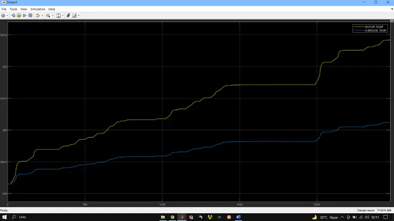
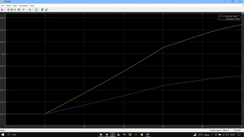
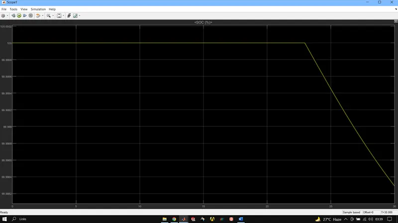
Results: For any three standard driving cycles show energy consumption, temperature rise of motor and controller for 100 km constant speed driving at 45 kmph.
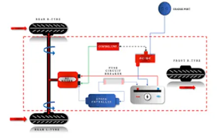
Battery Electric Vehicles (BEVs), compared to classic internal combustion engine (ICE) vehicles, are fairly simple and easy to operate. The simplest powertrain architecture consists in a high voltage battery, an electric motor with power electronics controller and a single speed gearbox. BEVs are also called pure electric vehicles, in order to distinguish them from Hybrid Electric Vehicles (HEVs), which have a hybrid powertrain (internal combustion engine plus electric motor).
In a BEV the propulsion is based exclusively on the electric energy stored in the high voltage battery. Battery electric vehicle are increasing their market share because they are the most viable way towards a clean and efficient transport system. Compared with ICE vehicles, the most important advantages of a BEV are the overall high efficiency, reliability and relatively low cost of the electric motor. The main drawback is the low energy density of the high voltage battery.
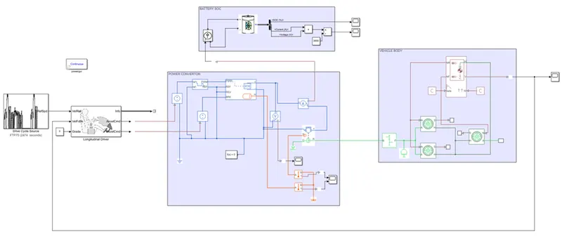
SIMULINK MODEL OF E-RIKSHAW
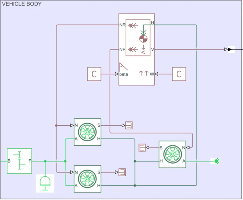
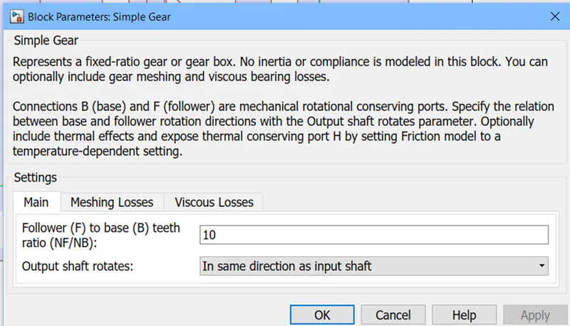
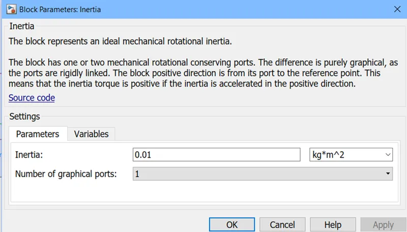
SIMPLE GEAR BLOCK, represents a fixed-ratio gear or gear box.
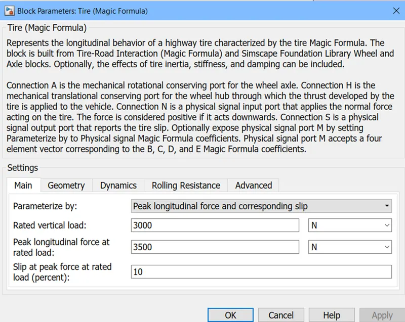
SIMPLE TIRE BLOCK, represents the longitudinal behaviour of a highway tire characterized by the tire Magic Formula. The block is built from Tire-Road Interaction (Magic Formula) and Simscape Foundation Library Wheel and Axle blocks. Optionally, the effects of tire inertia, stiffness, and damping can be included.
N represents normal reaction acting on tire, while H represents translational speed hence all 3 are connected and A represents rotational speed hence both tire on same axel is connected.
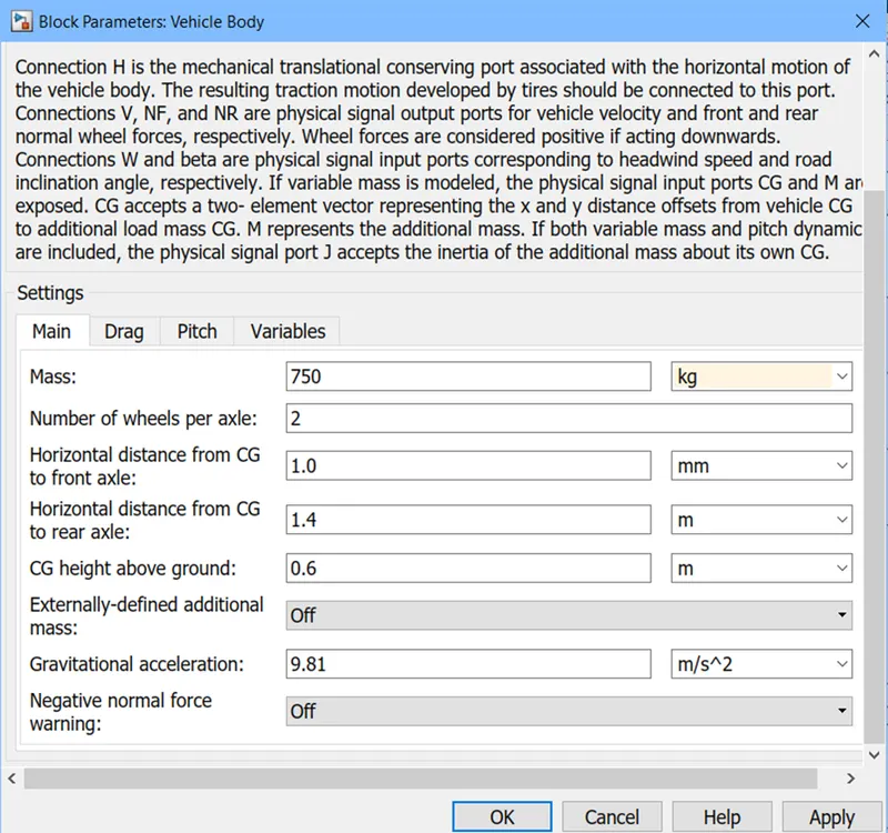
VEHICLE BODY BLOCK, represents a two-axle vehicle body in longitudinal motion. The block accounts for body mass, aerodynamic drag, road incline, and weight distribution between axles due to acceleration and road profile. The vehicle can have the same or a different number of wheels on each axle. Optionally include pitch and suspension dynamics or additional variable mass and inertia. The vehicle does not move vertically relative to the ground. NF represents the front axle neutral reaction force while NR is the same for rear axle. V is the output velocity beta is the road inclination angle and W is the headspeed.
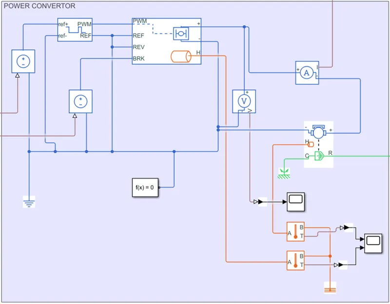
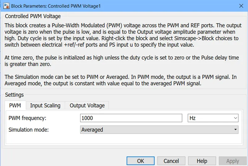
CONTROLLED PWM VOLTAGE BLOCK, this block creates a Pulse-Width Modulated (PWM) voltage across the PWM and REF ports. The output voltage is zero when the pulse is low, and is equal to the Output voltage amplitude parameter when high. Duty cycle is set by the input value.
It is used to provide proper pulse inputs to H-bridge circuit.
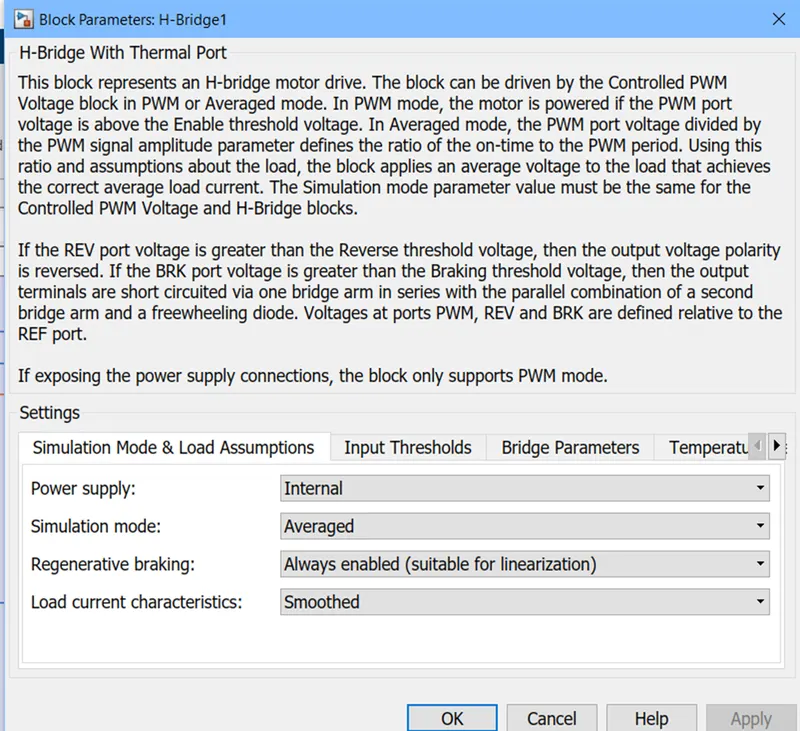
H-BRIDGE BLOCK, this block represents an H-bridge motor drive. The block can be driven by the Controlled PWM Voltage block in PWM or Averaged mode. In PWM mode, the motor is powered if the PWM port voltage is above the Enable threshold voltage. In Averaged mode, the PWM port voltage divided by the PWM signal amplitude parameter defines the ratio of the on-time to the PWM period. Using this ratio and assumptions about the load, the block applies an average voltage to the load that achieves the correct average load current.
REF port is the reference input which along with PWM port forms the pulse input for the circuit. REV port is for reversing of vehicle while BRK is for braking of vehicle whose input is given from controlled PWM voltage block.
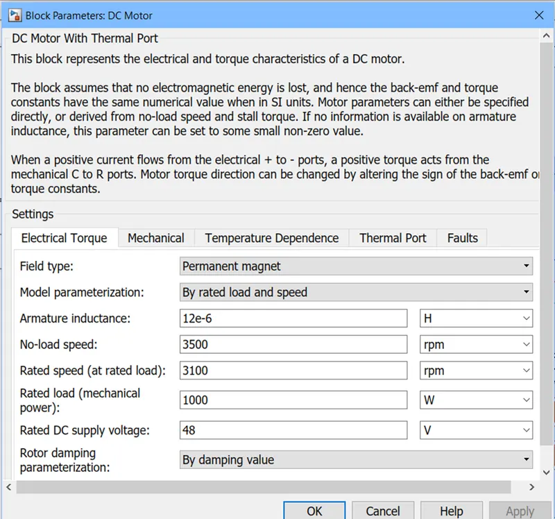
DC MOTOR BLOCK, his block represents the electrical and torque characteristics of a DC motor. The block assumes that no electromagnetic energy is lost, and hence the back-emf and torque constants have the same numerical value when in SI units.
R port represents rotor and is fed as input to vehicle velocity while C port is for stator hence is connected to a mechanical reference.
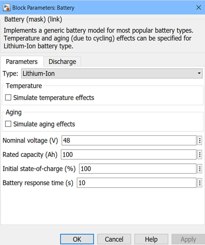
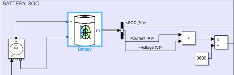
SIMPLE BATTERY BLOCK, this block models a battery. To ensure supply of current as required by motor controller and not rated values, currents sensor and controlled current source is connected along with it.
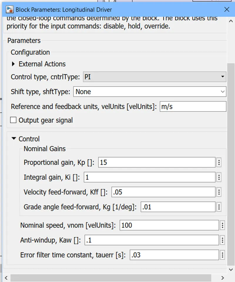
LONGITUDINAL DRIVER BLOCK, A parametric longitudinal speed tracking controller for generating normalized acceleration and braking commands based on reference and feedback velocities.
VelRef port is where input velocity from drive cycle data is fed, VelFed is the port where actual output velocity from the vehicle is feedback to the system which helps to reduce the error between input and output speeds. Grade port is used to input grade angle while Info port gives out bus signal for various parameters. AccelCmd and DecelCmd ports are used to fed acceleration and deceleration input values.
RESULTS
FOR FTP75
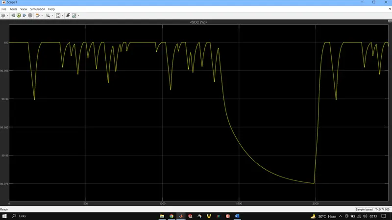
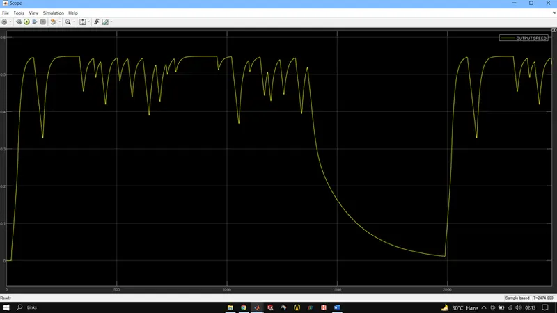
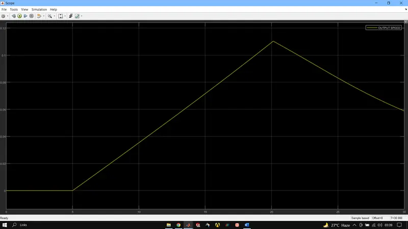
FOR WOT
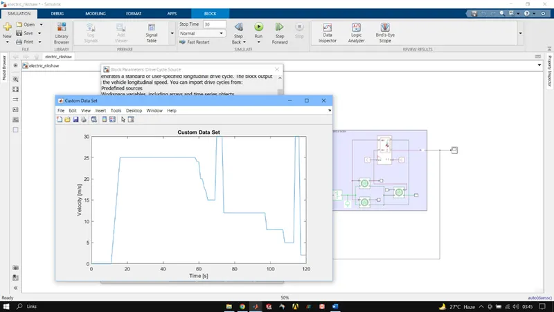
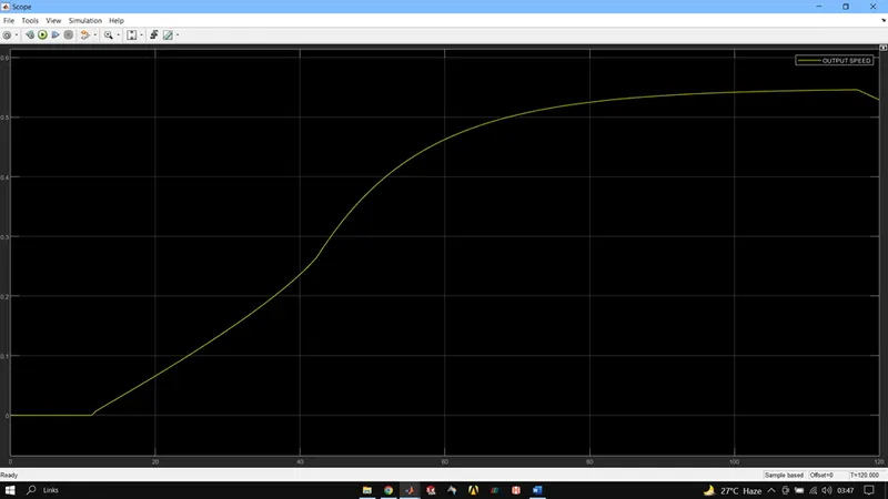
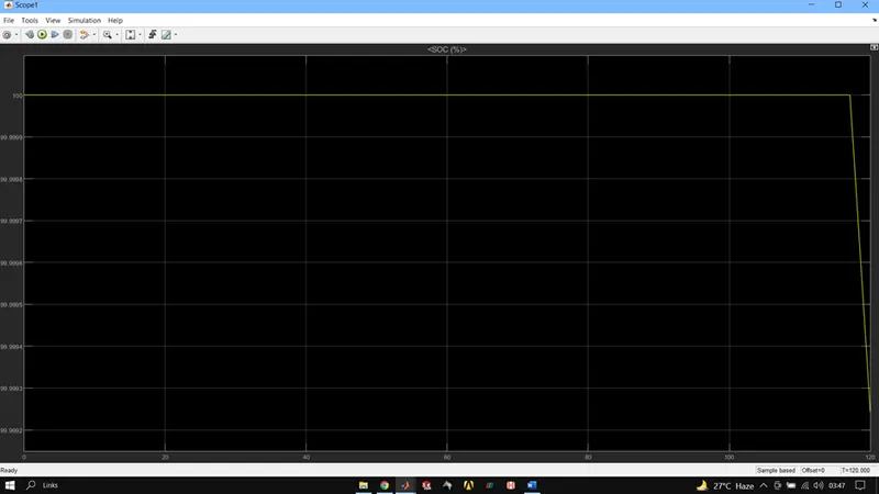
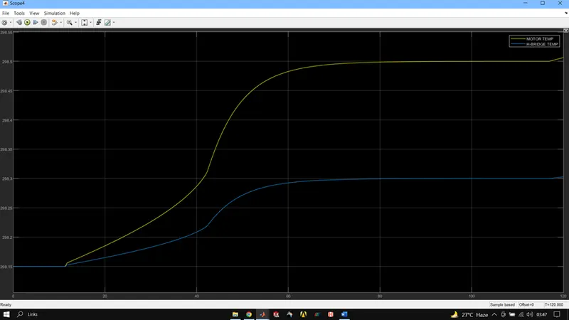
FOR CUSTOM DRIVE CYCLE
CONCLUSION
Thermal, mechanical and electrical these 3 properties of all the components in powertrain should be well managed and regulated for safe working of the powertrain.
EV is the new future and its application in daily commute passenger vehicles such as E-Rikshaw would bring up a huge impact. And an E-rikshaw can be designed with moderately powered motor and battery pack for sufficiently giving the desired results.
Proper tuning of controllers is necessary to have high accuracy between reference speed and output speed.
Proper thermal management solutions should be implied to ensure proper working of all electronics such as motor and controllers and converters.