Final Project: Electric Rickshaw modelling
AIM
- To create a MATLAB model of an electric rickshaw (three-wheel passenger vehicle) that uses a battery and a PM brushed type motor by choosing suitable blocks from the Powertrain block set and to prepare the report for the model.
OBJECTIVES
- Rear wheels driven by PM brushed type motor
- Model parameters
- Results
- Conclusion
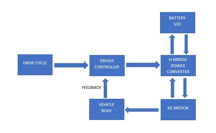
BLOCK DIAGRAM OF ELECTRIC RICKSHAW
SIMULINK MODEL
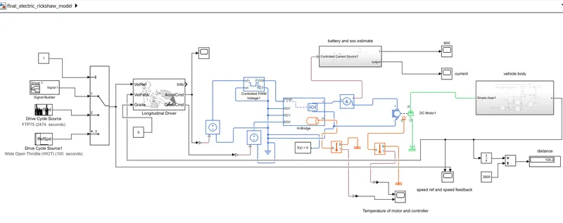
The model consists of the following,
- Vehicle body subsystem
- DC motor
- H-Bridge
- Controlled PWM voltage
- Battery and SOC estimate subsystem
- Longitudinal Driver
- Drive cycle source
A brief explanation of the model
The longitudinal driver block inputs the drive cycle source and the velocity feedback from the vehicle body. based on them it generates acceleration and deceleration commands which are given as input to the controlled PMW voltage block (acceleration command) and H-bridge block BRK (deceleration command). the DC motor is controlled by the H-bridge converter and connected with the battery through the controlled current source. the pulse signal generated from the PWM voltage block is used to control the H-bridge. the motor rotational output is connected with gear and rear wheels and again the velocity output from the vehicle body is given as feedback to the longitudinal driver block. the state of charge is estimated. the distances are calculated and the temperature of the motor and controller(H-bridge) are also measured.
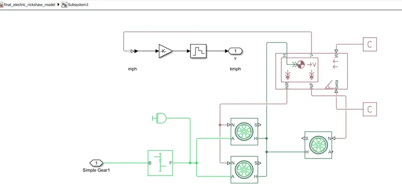
Vehicle body subsystem
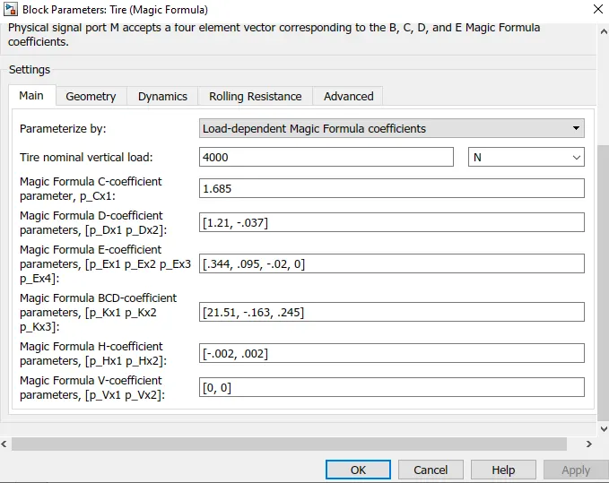
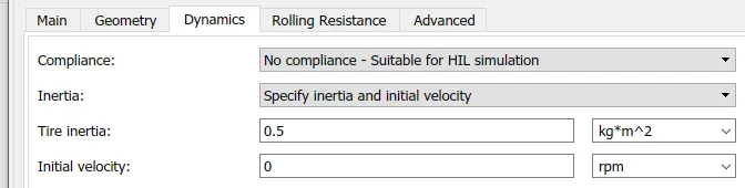
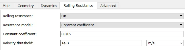
Tire
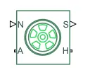
- It represents the longitudinal behavior of a highway tire characterized by the tire Magic Formula.
- A is the mechanical rotational conserving port for the wheel axle and here the rear wheel ports A are connected to the simple gear block as they are rear-wheel drive.
- H connections are the mechanical translational conserving ports for the wheel hub which are connected to the H port of the vehicle body
- N connections are the physical signal input ports that apply the normal force acting on tires
- S is a physical signal output port that reports the tire slip and in this model, we didn't consider the tire slip.
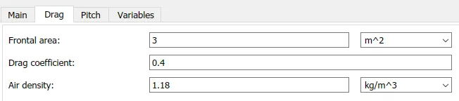
parameters,


Vehicle body

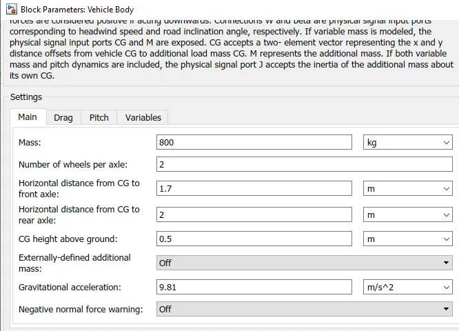
- H is the mechanical translational conserving port associated with the horizontal motion of the vehicle body. The resulting traction motion developed by tires, (connection H of tires block) should be connected to this port.
- V is the output port for the vehicle velocity
- NF and NR are physical signal output ports where normal forces acting on the front and rear wheels are connected.
- W and beta are physical signal input ports corresponding to headwind speed and road inclination angle. which are connected to the PS constant.
parameters,


simple gear
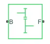
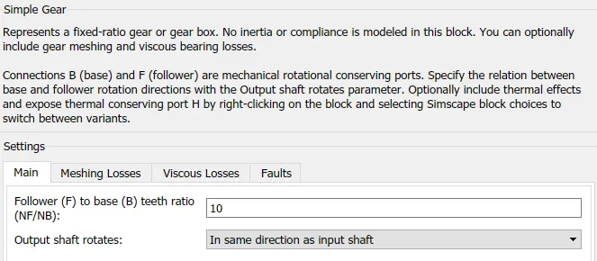
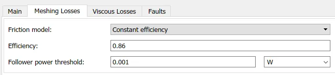
- In this model, I have used a fixed-ratio gear. B (base) and F (follower) are mechanical rotational conserving ports.
- the direction of rotation, gear tooth ratio, and other losses can be given through the block parameters
parameters


Inertia

- This block represents an ideal mechanical rotational inertia. the block has one mechanical rotational conserving port. the block positive direction is from its port to the reference point. this means that the inertia torque is positive if the inertia is accelerated in the positive direction.
For converting mph to kmph,
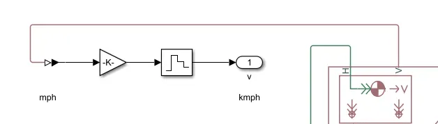
- the output V(mph) from the vehicle body is connected to gain block with value 1.61 through the PS-Simulink converter and then to zero-order hold which holds its input for the sample period and then to output V(kmph)
DC motor
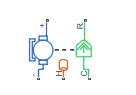
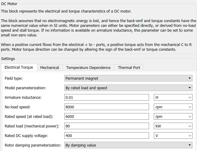
- This block represents the electrical and torque characteristics of a DC motor.
- the blue part indicates electrical and the green part indicated mechanical ports.
- port C is casing connected to mechanical rotational reference and port R is connected to the simple gear of the vehicle body subsystem.
- when a positive current flows from the electrical + to - ports, a positive torque acts from the mechanical C to R ports.
- Motor torque direction can be changed by altering the sign of the back-emf or torque constants.
- they are controlled by H-Bridge block
- port H will be connected to the temperature sensor for measuring the motor temperature.
- to add thermal mass right-click on the dc motor block then select Simscape-block choices-show thermal port.
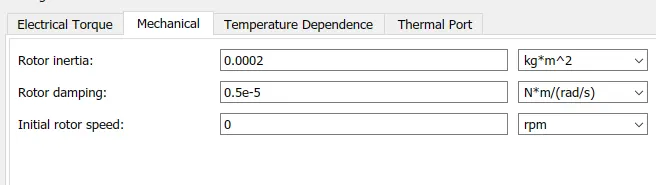
parameters


H- Bridge
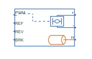
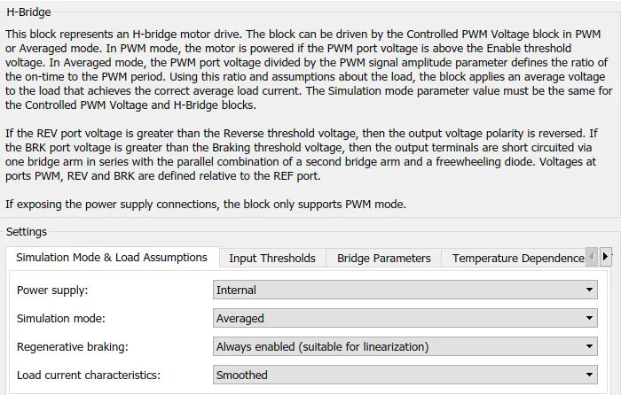
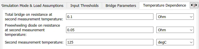
- This block represents an H-bridge motor drive that is used to control the DC motor in this model.
- By using semiconductor switches and freewheeling diodes the output voltage to the DC motor can be controlled.
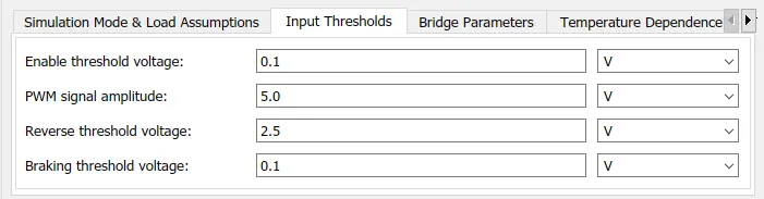
- Input for this block is given by controlled PWM voltage block and with the relation of input signal REF, REV, BRK, and the threshold voltage, the output voltage is controlled.
- here we are considering regenerative braking BRK (deceleration command from the driver controller) but the reverse REV is grounded by electrical reference.
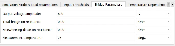
- the output voltage amplitude should be the same as the rated DC supply voltage.
- port H will be connected to the temperature sensor for measuring the controller temperature.
- to add thermal mass right-click on the H-bridge block then select Simscape-block choices-show thermal port.
parameters

Controlled PWM voltage
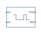
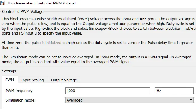
- It is used to create a Pulse-Width Modulated (PWM) voltage across the PWM and REF ports. where the PWM port is connected to the H-Bridge PWM port.
- The output voltage is zero when the pulse is low and is equal to the output voltage amplitude parameter when the pulse is high.
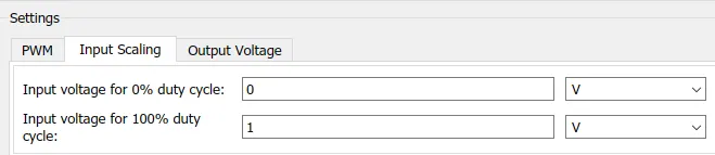
- we can set the duty cycle by the input value.
parameters

Battery and SOC estimate subsystem
Battery
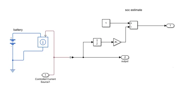
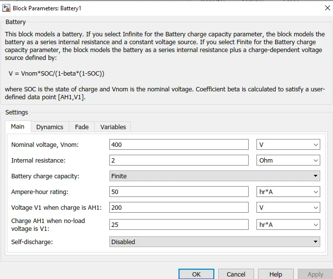
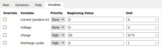
- A battery with 400V nominal voltage and finite charging capacity is selected for this model. the positive terminal is connected to the controlled current source and the negative terminal to electrical reference.
parameters,


controlled current source
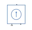
- Represents an ideal current source that maintains the specified current through it regardless of the voltage across it.
SOC estimate
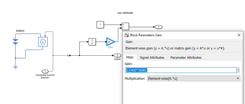
- To estimate the state of charge ( the ratio of the available capacity and the maximum possible charge that can be stored in a battery ) and how much the battery is discharged, the output from the PS-Simulink converter is connected to the integrator block (continuous-time integration of the input signal) and then to gain block with the value 1/(400*3600) where 400 is the nominal voltage and 3600 sec. then subtracted from 1.
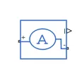
- It converts current measured in any electrical branch into a physical signal proportional to the current.
- In this model current sensor is connected in series with the H-bridge and DC motor.
- the physical signal from the current sensor is connected to the controlled current source block and PS-Simulink converter in the SOC estimate subsystem.
controlled voltage source

- It is used to maintain the specified voltage at its output regardless of the current passing through it.
Temperature sensor
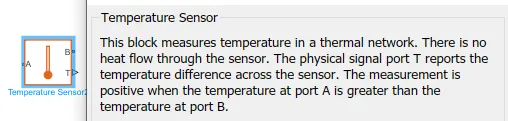
Distance calculation
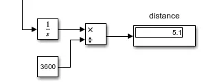
- To calculate the total distance for this drive cycle the output Velocity from the vehicle body is integrated and divided by 3600.
Other blocks used,

- scope and display blocks are used for observing results.
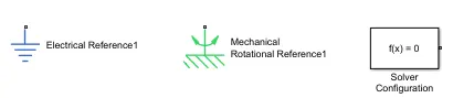
- the references and solver configuration are necessary for the simulation of the model.
Longitudinal driver
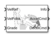
- This block is a parametric longitudinal speed tracking controller which generates normalized acceleration and braking commands based on reference and feedback velocities.
- we are using this block as to how the driver controls the acceleration and deceleration.
- In this model, the grade is connected to a constant block
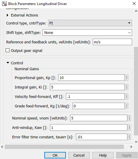
parameters,
Drive cycle
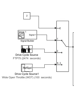
- 3 drive cycles are used here.
- a multiport switch is used to select the drive cycle
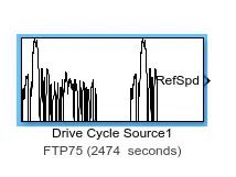
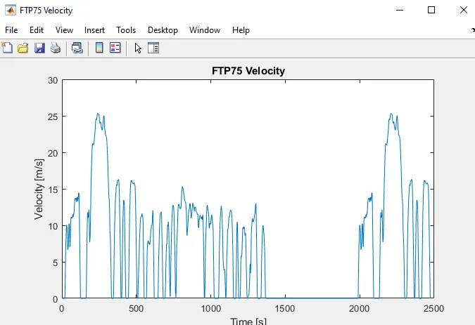
1. FTP75 (2474 seconds)
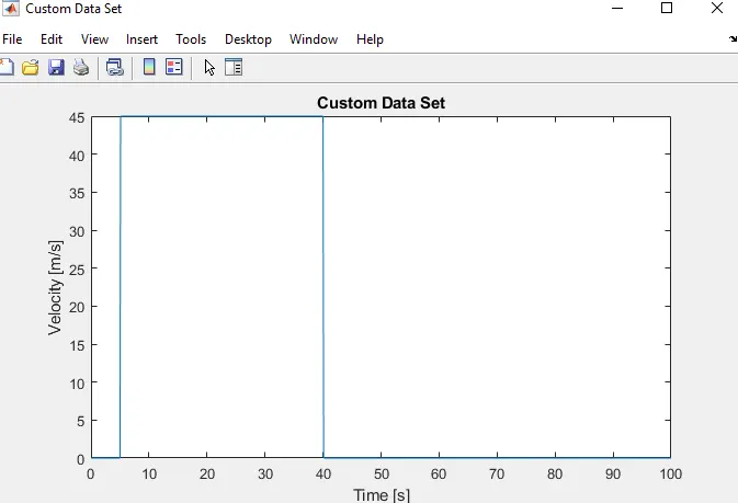
2. Wide-open throttle (WOT) 100 seconds
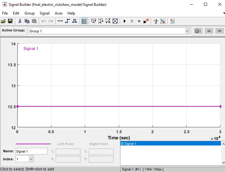
3. using a signal builder (custom-30000 seconds)
- for achieving 100 km of distance at a constant speed of 45 km/h.
- here 45km/h is converted to 12.5 m/s
RESULTS
1. FTP75 (2474 seconds)
speed reference and speed feedback
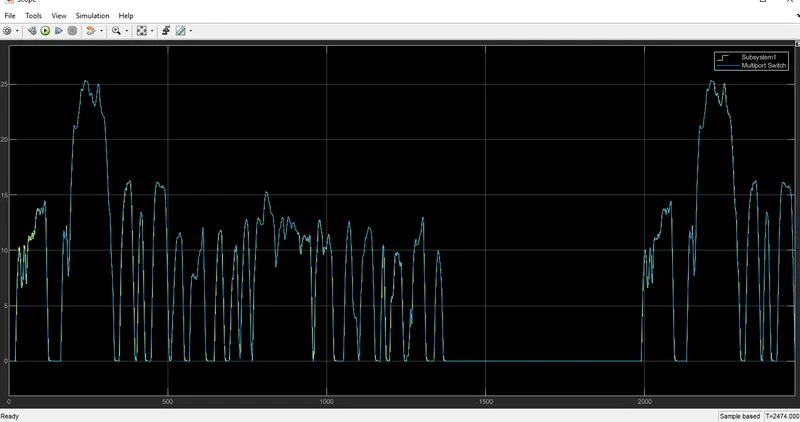
- we can observe two different drive cycles, the blue is the FTP75 source drive cycle, and the yellow is the velocity output from the vehicle body which is given as feedback to the longitudinal driver block.
- The two seem to be overlapping with slight variation when the velocity becomes 0.
SOC
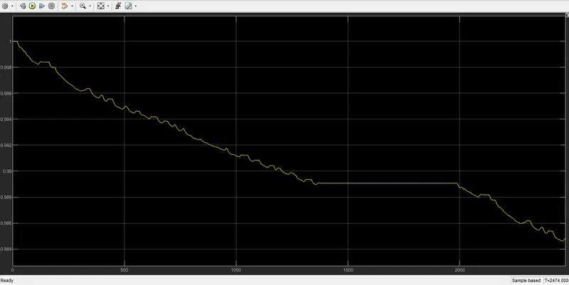
- we can observe very less amount of battery is used for the given drive cycle, above parameters and the simulation time is 2474 sec
- there are a lot of times where the line seems to raise a bit indicating the regenerative braking operation.
Motor and controller temperature
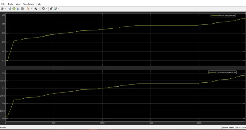
- the motor temperature is 530 °C approx
- the controller temperature is almost 301 °C
Distance traveled
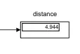
- For the given drive cycle FTP75 (2474 sec), the vehicle can travel to a distance of 4.9
2. Wide-open throttle (WOT) 100 seconds
speed reference and speed feedback
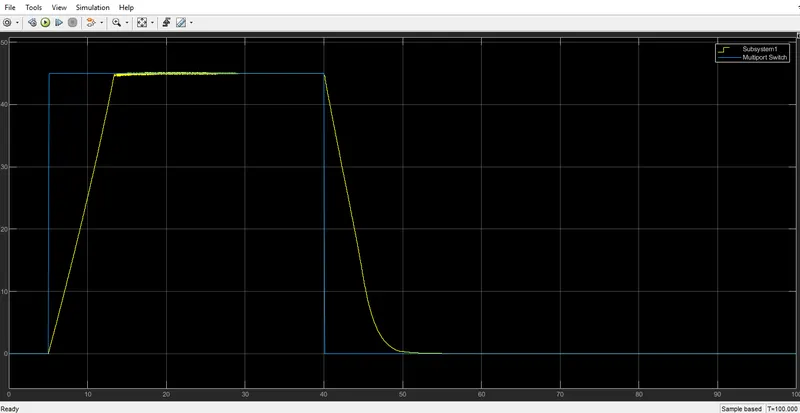
- here the feedback speed from the vehicle body takes some time to match up the reference speed both while acceleration and deceleration
SOC
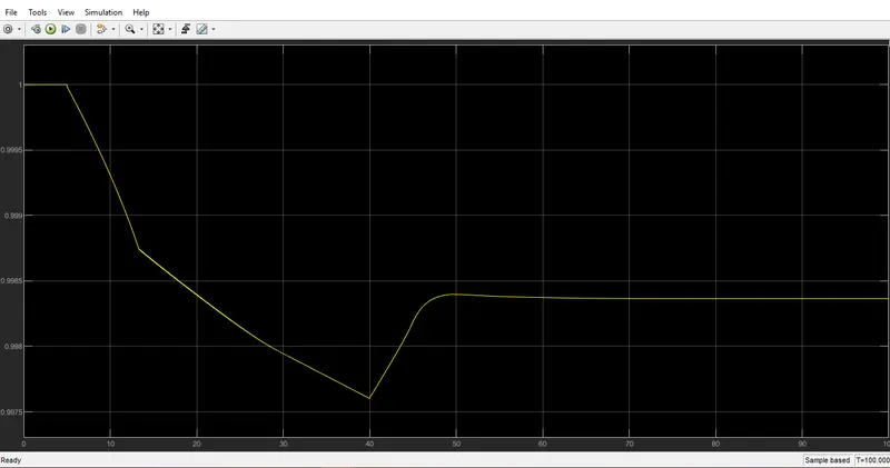
- for this drive cycle, the usage of the battery is very less.
- we can observe that while acceleration the SOC gets dropped and when braking the SOC gets raised meaning the battery is getting charged. and while velocity is 0 the SOC is also constant.
Motor and controller temperature
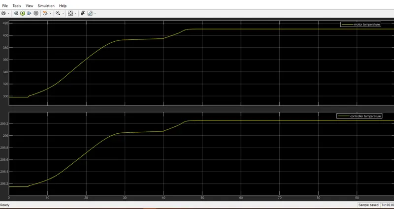
- the motor temperature is 410 °C approx
- the controller temperature is around 299.2 °C
Distance traveled
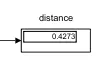
- For the given drive cycle WOT (100 sec), the vehicle can travel to a distance of 0.4273
3. using a signal builder (custom-30000 seconds)
speed reference and speed feedback
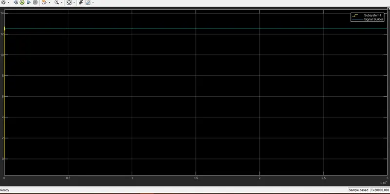
- here both the speed reference and speed feedback are matching.
SOC
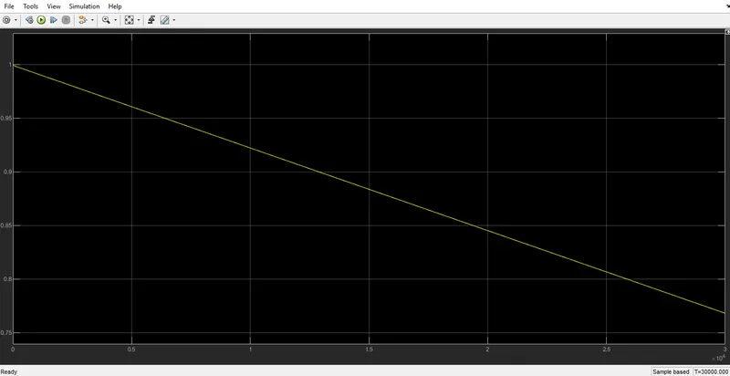
- here SOC dropped from 1 to almost 0.75, 25% of the battery is used for this drive cycle.
- we can see a steady dropping in the graph because this drive cycle is designed in the way that to travel around 100 km of distance at a constant speed of 45 km/h.
Motor and controller temperature
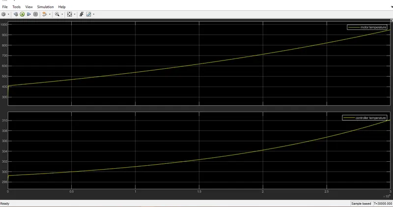
- the motor temperature is 950 °C approx
- the controller temperature is around 310 °C
Distance traveled
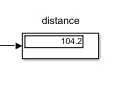
- For the given drive cycle signal builder (30000 sec), the vehicle can travel to a distance of 104.2
CONCLUSION
Thus a MATLAB model of an electric rickshaw with suitable blocks from the Powertrain block set is created. for the three drive cycles with the above parameters and system configuration, we have calculated the velocity, state of charge, the temperature of the motor and controller, and distance and observed the results through various scopes and display.
google drive attachment link: https://drive.google.com/file/d/1sX8mbXkUKP_ebxAnWXWBpKtvBL_9WfrB/view?usp=sharing