Final Project: Electric Rickshaw modelling
Aim :-
To Create a detailed MATLAB model of an electric rickshaw (three wheel passenger vehicle)
Objective :-
- Rear wheels driven by PM brushed type motor
- Assume efficiency points of motor controller and motor
- Make an excel sheet of all input and assumed data
- Results: For any three standard driving cycles show energy consumption, temperature rise of motor and controller for 100 km constant speed driving at 45 kmph.
Block diagram :-
 Design of an Electric Vehicle : Skill-Lync" />
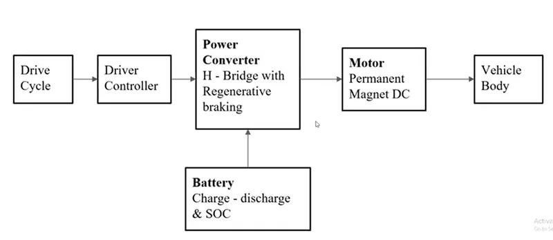
In these design of "Electric rikshaw" main block are battery, drive cycle , controller , DC motor Vehicle body & transmission system. Drive cycle is the input data for vehicle like how the human drive the vehicle here we give the drive cycle such as FTP75,WOT, excel sheet input data manually prepared for vehicle. The main objective is to obtain the speed by the driver to estimate the temperature of motorand controller, SOC,distance travelled by vehicle.There is SOC block which eastimate the SOC of battery and distance is calculate by the speed time parameter.
- Simulink model of electric rikshaw:-
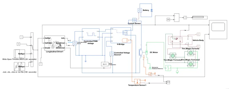
Initially the curretn flows to DC motor from battery through DC-DC converter to drive thr motor. The rquired voltgae is controlled by controller.The controller will follow the drive cycle reference and run the motor in required form. then the motor power will transfer to wheel of vehicle through gear box.
Model Parameter :-
- Drive cycle
Drive cycle is assume as driver input for vehicle it replaced how driver will drive the vehicle. here I used thre drive cycle for testing the vehicle performance.These drive cycle having high speed , low speed,breaking condition. There are different drive cycle like WOT,FTP75 etc.
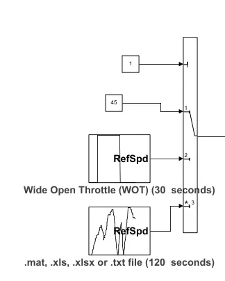
Generate a standard or user specified logitundinal drive cycle. The block output is the vehicle logitudinal speed. as you can import drive cycle from :-
predefined source
Workspace vaeiable ,including array and time series object
mat,xls,xlsx,or text files.
Use fault tracking parameter to identify drive cycle faults within specify speed and time tolreance.
- Wide open throttle:-
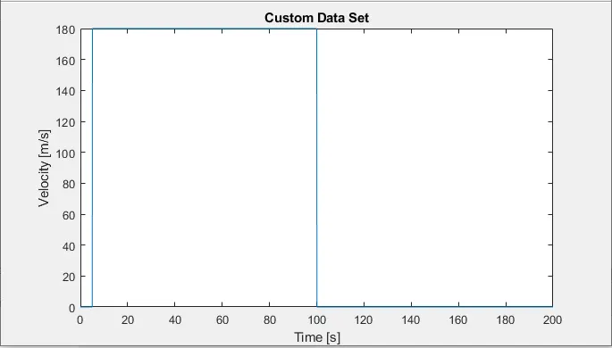
- Manually prepared drive cycle :-
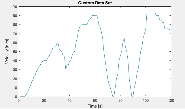
All these drive cycle controlled by controller provided above by constant through multi-port switch.
- Drive Controller :-
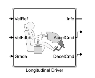
A parametric longitudinal speed tracking controller for generating normalized acceleration and breaking command based on reference and feedback velocity. Use external action to input signal that can be disable, hold and override the closed loop command determined the block. The block uses this priority for input command such as disable, hold, override.
Drive cycle is connected to longitudinal driver, it has six port generally voltage reference, voltage feedback, grade, info, acceleration, deceleration.
voltage reference is given by drive cycle data, voltage feedback is given by output of motor. This two will get compare and the acceleration or deceleration output is given to motor controller. Accelcmd is given to PWM generator block and deccelmd is given to regerative port of H-bridge which is use for regerative breaking. Info is used to get any other data from logitundinal driver block. Grade is use to give the input of gradeablity to driver block. I use default parameter and controlled type PI
- Motor controller :-
- Motor type : DC motor
This block represent the electrical and torque characteristic of Dc motor include thermal portto sense the temperature of motor. This block assume that no electro-magnetic energy is lost, and hence the back emf and torque constant have same numerical value when in SI unit.The motor parameter can either be specified directlyor derived from no load and stall torque.If no information is available on armature inductance this paramter can be to some small non zero value.
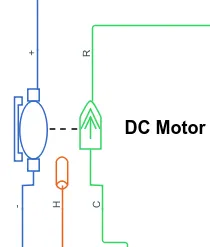
When positive current flow from the electrical + to - port, a positive torque act from mechanical C to R port . Motortorque direction can be changed by altering the sign of back -emf or torque constant.
- Motor parameter:-
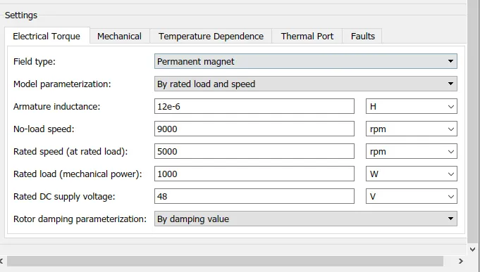
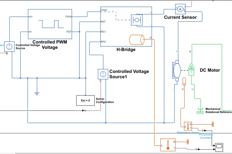
The motor controller will get input from longitudinal driver .Its task are to controlt he speed of motorand drive according to input of driver. Majorly motor controlled we designed had two main part named PWM voltage generator and H bridge.
Input 1 is get from the Accelmd of a longitudinal driver and it is given to controlled voltage source block where it is input to controlled pwm voltage. controlled pwm voltage will generate PWM signal in such away that H bridge wil generate required voltage to operate DC motor for the given driver input. PWM voltage block negative reference and REF are grounded and REF of H-bridge respectively. H-bridge is a motor controller that has IGBT component aligned int he shape of H and will operate only two at a time repectively to the input of signal from the PWM block. when deceleration occured this H- bridge will give an ouput from the + and - terminal of it. These negative and positive terminal are later connect ot the DC motor and battery. All these component arethe simscape electrical component so they need a connection to the solver configuration block which help to sove the simulation.
- Controlled PWM voltgae source :-
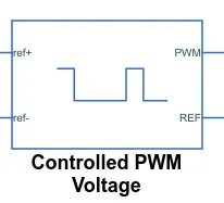
This block create a pulse-width modulated [PWM] voltage across the PWM and REF port. The output voltage is zero when the pulse is low and is equal to the output voltage amplitude parameter when high. Duty cycle is set by the input value. Right click the block and select simscape-->block choice to switch between electrical + ref /- ref port and PS input is too specifiy input value.
At time zero, the pulse is initialse as high unles the duty cycle is set to zero or the pulse delay time greater than zero.
The simulation mode can be set to PWM or average. In PWM mode, the output is a PWM signal. In PWM mode, the output is constant with value equal to average PWM signal.
Select simulation mode as averaged.
- Power converter :-
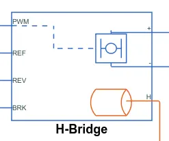
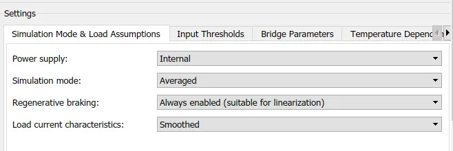
This block represent an H-bridge mtor drive. The can be driven by the controlled PWM voltage block in PWM or averaged mode. In PWM mode,, the motor is powered if the PW port voltage is above the enable threshold voltage. In averga emode, the pwm port voltage divided by the pwm signal amplitude parmeter defines the ratio of the on-time to pwm period. Using this ratio an assumption about the load, the block applies an average voltage to the load that achieve the correct average load current. The simulation mode parameter value must be the same for the controlled pwm voltage H-bridge block.
If the REV port voltage is greater than the reserved threshold voltage, then the output voltage polarity is reserved. if the BRk port voltage is greater than the breaking threshold voltage, then the output terminal and short circuited via 1 bridge arm in series with the parallel combination of second bridge arm and a freewheeling diode.Voltage at port PWM, REV and BRk and defined relative to the REF port.
If exposing the power supply connection,the block only support PWM mode.
Motor Controller Parameter :-
- Temperature sensor :-
Temperature sensor is used to measure the temperature of H-bridge and motor.
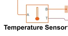
This block measure temperature in a thermal network. there is no heat flow through the sensor. The physical signal port T report the temperature difference across the sensor. The measurement is positive when the temperture at port A is greater than at port B.
- Solver configuration :-
Define solver setting to use for simulation
- Reference :-
- Electrical Reference:- Use to ground all the electrical connection.
- Mechanical rotational Reference :- Use to ground all the mechanical rotational part.
- Thermal Reference:- Use to ground all the thermal sensor.
- Battery:-
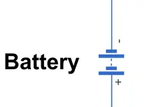
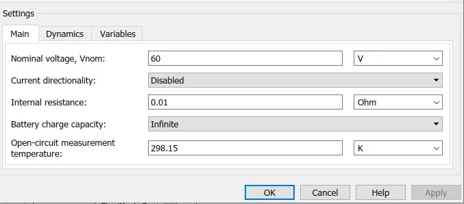
The battery is required to power the controller and motor. The controller uses the bettery power according to produce the input given by the motor to obtain maximun speed.The battery is also used to power every elctrical component in the vehicle. The battery has two stage one is changing and another one is discharging stage.
- Vehicle body and transmission:-
Motor will produced the rotational output which will give to the vehicle body and trasmission system. The rotational output is taken by the gear system.Here to maintain the constant speed through out the transmission without any loss in speed from the motor tire. Below is a diagram that is how it inside the vehicle body and transmission system and in the main design it is refer just only as a transmission system. Hence I created a rear wheel drive transmission system.
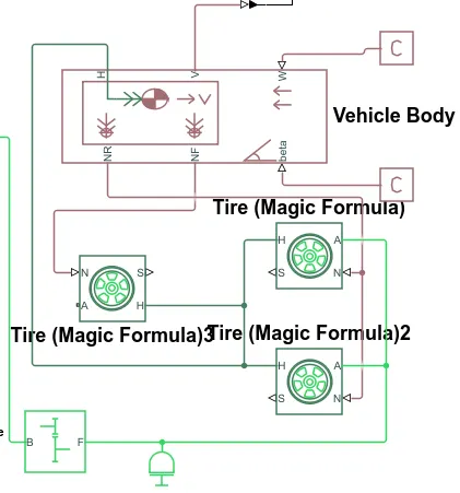
The gear output is given to axle of rear tire in the circuit it is shown that gear is connect to rear wheel and front tire is free to rotational motion.Thus vehicle moved forward.N is the normal force caused by the tire and it is given to vehicle body normal force port. the vehcile body has an H-hub, S-tire slip, N-Normal force, A-Axle connection ,Wind velocity, inclination angle.This tire hub is connected as a common node to vehicle body. vehicle body wind velocity is connected to the constant block and beta inclination angle is connected to another constant block. Where we can assign wind velocity and inclination angle as per requirement. velocity is the output port where we can get at which speed the vehicle is moving. Th velocity is taken out to the gate the distance travel and SOC.
- Wheel:-
Represent the longitudinal behaviour of a highway tire characterise by the tire magic formula. The block is built from tire road interaction [magic formula] and simscape foundation library wheel and axle block. Optionally, the effect of tire inertia stiffness and damping can be included.

Connection A is mechanical rotational conserving port for the wheel axle, conncetion H is a mechanical translational conseriving port for the wheel hub through whcih is delveloped by the tire is applied to the vehicle. Connection is physical signal input port that aplies the normal force acting on the tire.The force is consider positive if it act downward. Connection S is physical signal output port that report the tire slip.Optionally expose physical signal port m by setting parameterzed by to physical signal co-efficient.Physical signal port m accept a four element vector corressponding to the BCDE magic formula co-efficient.
- Inertia :-
The block represent an ideal mechanical rotational inertia. The block has one mechnical conserving port.The block positive direction is from its port to the reference point. This means that the inertia torque is positive.If the inertia is acclerate in the positive direction.

- Simple gear block:-
Represent a fix ratio gear to gear box. No inertia or compliance in modeled in thid block.You can optionally include gear meshing and viscous bearing losses.
Connection B and F are mechanical rotational consering port.Specify the relation between base and follower rotation direction with th eoutput shaft rotate parameter. Optionally inlcude thermal effect and expose thermal conserving port H by right clicking on the block and select simscape block choice to swith between varient paragraph output shaft rotate in same direction of input shaft.
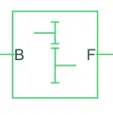
Base is connected to the motor shaft and follower is connected tothe rear wheel device
- Result:-
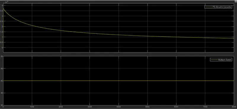
For constant 45 Speed of vehicle , the vehicle covered the 3.15 Km distance. To increase the speed of vehicle The output voltage amplitude is applied 400V.
- Conclusion :-
- I created the MATLAB model of elctric rikshaw by using the battery and DC motor.
- I compromised the temperature of motor and controller to achieve the vehicle speed is near to reference speed .since I haven't used any cooling system in the model. In real timeapplication,the motor temperature is less than 100 degree celsius.
- In real time application, the motoe and battery and controller temperatureis controlled by air cooling Hence the temperature of this component is not increased to htis extent.
- The battery powered rickshaw will be most popular mode in future.