Final Project: Design of an Electric Vehicle
AIM :
Create a MATLAB model of electric car which uses a battery and a DC motor.
Theory :
An Electric vehicle is a vehicle that uses one or more electric motors or traction motors for propulsion.An electric vehicle may be powered through a collector system by electricity from off-vehicle sources,or may be self-contained with a battery,solar panels,fuel cellsor an electric generator to convert fuel to electricity.
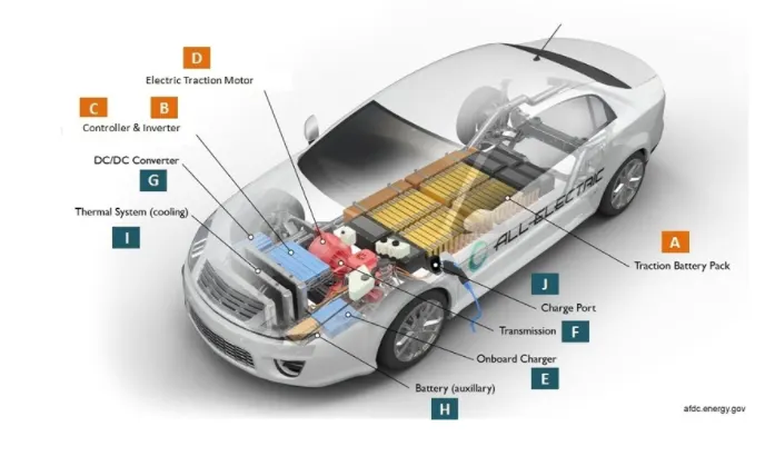
The main componenets of an EV :
1) Battery - The battery of an electric vehicle can be charged through the use of ordinary grid electricity at a specialized power station.But aside from the conventional lithium-ion battery technologies,there are also other major battery technologies which can be used for electric cars.
*Lithium-ion batteries:This battery technology gives extra peformance and range.However it also carries the highest price tag,Lithium-ion batteries are lighter than Lead acid and Nickel metal batteries.
*Lead Acid Batteries:This bettery technology is the most popular and it is also the cheapest among the battery technologies.The good thing about it is 97% recyclable.
*Nickel Metal Hydride Batteries: This battery technology provides higher output and better performance but it costs much more than lead-acid batteries.
2) Motor Controller - The motor controller of an electric car administers its complete operation and the distribution of its power at any given moment.It acts as a floodgate between the motor and batteries. It helps monitors and regulates all key performance indications such as the vehicles operator,motor,battery and accelerator pedal.It has a microprocessor which can limit or redirect current.It is used to either improve the mechanical performance of the car or suit the operaors driving style. These are also more refined controllers which are capable of greater accuracy and thus higher efficiancy.
3) Electric Motor - Unlike a gasoline engine with lots of moving parts,a motor only has one moving part.This makes it very reliable source of motive power. Choosing an electric motor depends on the cars systemvoltage.They can be structured to use either AC or DC current.AC motors are less expensive and lighter compared to Dc motors. They are also more common and they tens to suffer from less mechanical wear and tear.However AC technology requires more refined or sophisticated motor controller.
PROCEDURE:
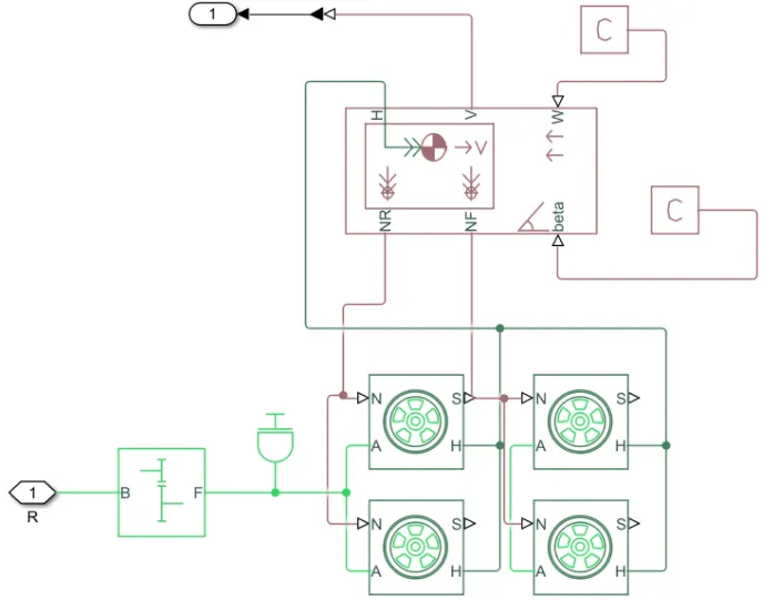
At first we design the body of the vehicle . The body will compromise of four wheels and these wheels are getting the power from the motor but only after getting through the transmission which in this case is a simple gear .
Fig 1 : Vehicle body
We will create the subsystem of these blocks. Then the motor will be made using the brushless Dc motor.
Fig 2 : DC motor drive
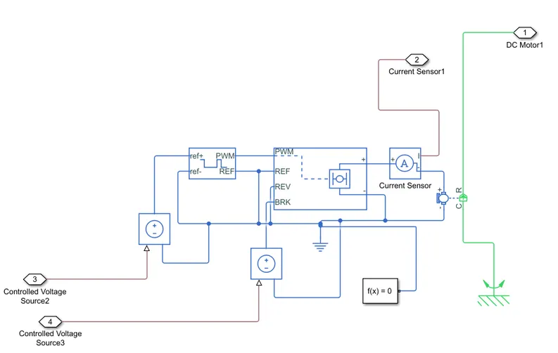
We will make use of the H-bridge rectifier to convert AC current to Dc current. For the duty cycle a PWM block is used and all the negative ends are connected to the electrical reference. Again this will be created as a seperate subsystem.Once this is done the power source is created.The simple voltage source is used for this purpose.The Negative end goes to electrical reference,whereas the positive end goes to the motor to provide the drive.A control current source is used and this is created as seperate subsystem.
Fig 3 :Battery
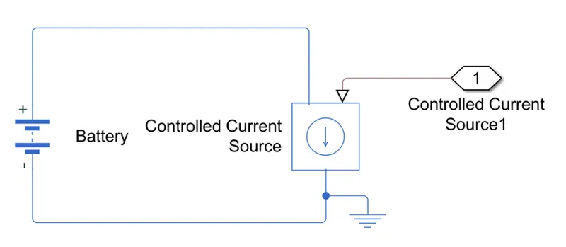
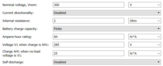
Once this is done we will configure the battery. The following is the configuration of the battery,Dc drive and vehicle body.
First for the battery the nominal voltage is set at 300V,Internal resistance is set at 2 ohm and the battery capacity is 2 Ah.
Battery configuration :
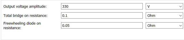
Secondly the motor is configured.The voltage here needs to be higher than the voltage of the battery.So here it is set as 330V and the total bridge on resistance is set at 0.1 OHM,whereas freewheeling diode resistance is taken as 0.05 OHM.
Configuration of Motor:
Thirdly , the PWM signal is configured. Here the frequency is set as 4000Hz whereas the simulation mode is set at average.
Configuration of PWM signal:

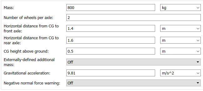
Lastly for vehicle body,the total mass is considered as 800kg.Rest we will configure with the default values. The number of wheels per axle is taken as 2.
Configuration of vehicle body :
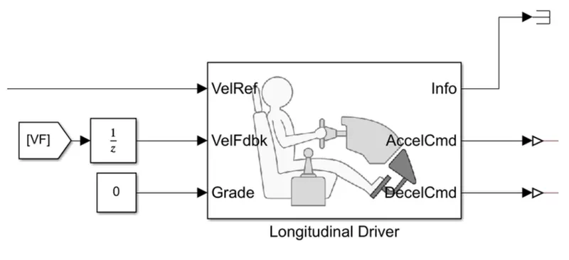
To provide the input to it , we will provide the longitudinal driver.The vehicle feedback is provided by the output of distance covered. Acceleration and decelaration are provided to the motor.The grade is assumed as 0.
Longitudinal Driver :
To provide traction we need a particular input from the user.The input can is the power required for a particular speed that is at every time interval we need the speed required at a particular load.
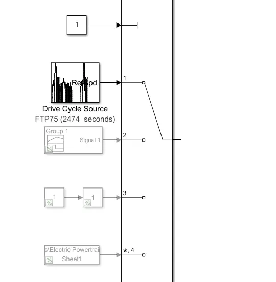
For this model i have selected FTP75 drive cycle.Using signal builder block the input can be provided.The slider gain is another method of providing the input. The electric powertrain can also be given using the excel sheet data of time vs speed.
Fig : List of drive cycle provided
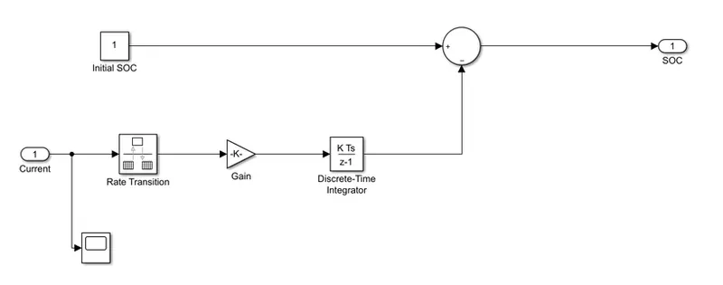
The state of charge is calculated with the current drawn from the battery.The following represents the conversion of the current into a state of charge.The difference between this with 1 will give the actual state of charge.
Fig :SOC Calculator
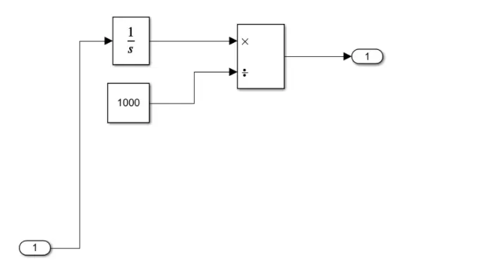
The output from the vehicle body is integrated at every time interval and it is divided by 1000 to convert into kilometer.
Fig: Distance covered calculator
Both of these are put into a subsystem to calculate the SOC and distance covered.
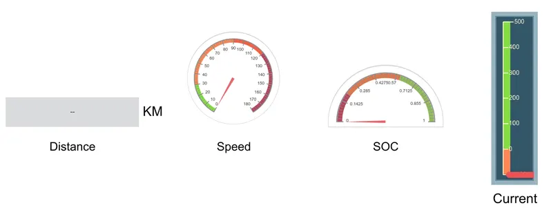
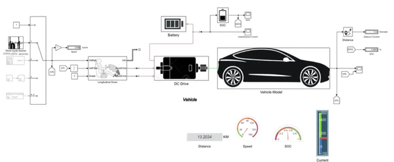
Below is the dashboard output for better visualization and the display block is used for showcasing distance. The speed and SOC are depicted by Full and Half gauge block.The current drawn is shown by the vertical gauge.
Fig: Dashboard
The final model is as follows :
Result:
1)Fig :Current drawn from battery
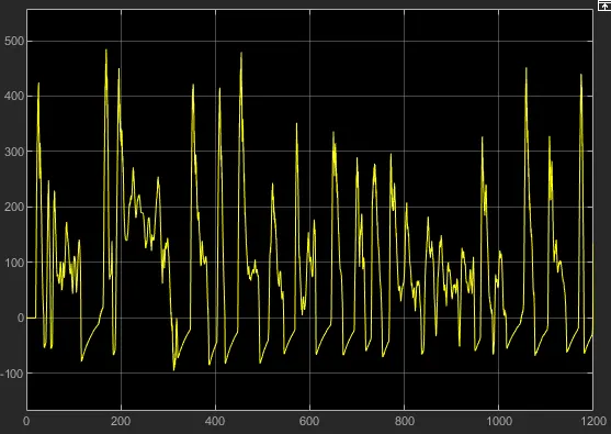
In the above graph It can be seen that it goes negative , it is because at the event of braking the battery gets charged due to degenerative braking .
2)Fig :State of charge
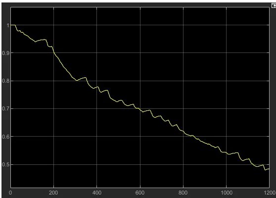
In the above graph when the vehicle applies brake the SOC is increasing marginally,whereas it decreases during the drive .
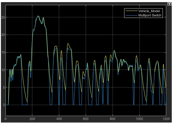
3)Fig : Input of Multiport switch and vehicle model
Conclusion :
The model was successfuly ran for simulation under the FTP75 drive cylce
The vehicle covered nearly 13.2 kms with FTP75 drive cycle
The SOC was almost half during the drive.