Final Project: Design of an Electric Vehicle
Create a MATLAB model of electric car which uses a battery and a DC motor. Choose suitable blocks from Powertrain block set :-
Block Diagram of Electric Vehicle ,
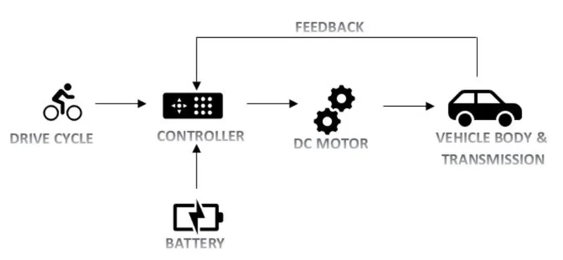
- In the designed EV model , the main blocks are driving cycle , controller , DC Motor , Vehicle body & Battery. Drive cycle is the driving pattern.
- For which this model is going to be tested or evaluated. The main objective here is to obtain the speed attained by the driver, the SOC (state of charge ) , distance travelled by the vehicle.
Main Simulink Model for the EV is shown below ,
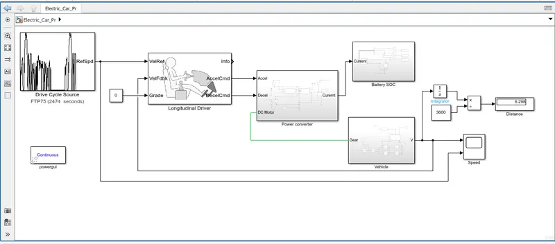
Deatil Explaination about various blocks ,
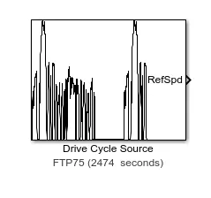
*Drive Cycle Source :-
- The range of electric vehicles is the major problem faced by the automobile industry because storing electrical energy efficiently is a very tough task for engineers.
- This is a critical issue in the design of any electrical vehicle. For that what we can do is test the vehicle by driving in reality or in simulation through a profile of ever-changing speeds.
- These test drive cycles have been developed to provide a realistic and practical test for the emissions of vehicles.
- Now for this model, the FTP75 drive cycle is chosen and with this cycle input reference, simulation of the model is done. With this simulation, the distance traveled by the vehicle at the end of this cycle is calculated using MATLAB software.
- In this drive cycle, the condition or the velocity of the propelling vehicle is noted at each second. The important data that needs to maintain as a record is the amount of charge removed from the battery, the depth of discharge of the battery, and the distance traveled.
- By taking these velocities as input and is fed to the longitudinal driver block. It calculates acceleration and thus the tractive effort, and thus the motor power, torque, and speed. Using this data motor efficiency can be found and also the electrical power going into the motor.
- This calculation is repeated every one second till the end of the cycle.
The parameters for this block were set as below :-

* Longitudinal Driver :-
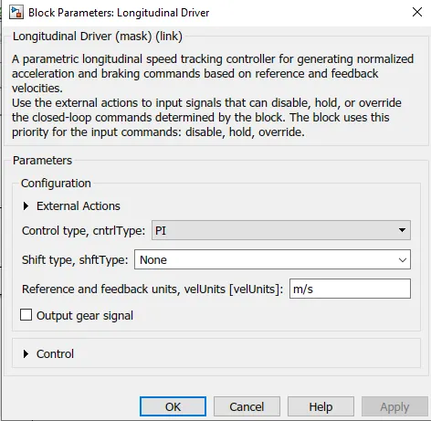
Longitudinal driver block calculates the Acceleration by taking 2 inputs one from drive cycle velocity & other one from vehicle traction velocity at each one second of time interval & is repeatedly provides the input to the voltage source till end of the drive cycle.
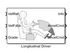
Longitudinal Driver Block's parameters ,
* Power Converter :-
Power Converter is needed to provide power of the correct form & magnitude from one component to other one.
In our case of EV's a power coverter is needed to provide a DC voltage from the battery of EV to the DC motor so that it can operate properly with the required parameters.
The Following arrangement shows the power coverter :-
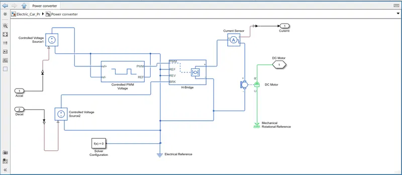
In our case i have used H - Bridge motor drive as my power conerter.
1. H - Bridge :-
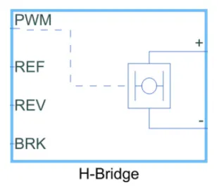
- The H Bridge has 2 sides to it: the left side is for the controlling of the voltage signals and the right side is for the terminals to provide the controlled voltage to the DC motor. The left side ports of the H-Bridge block are:
- PWM - This stands for Pulse Width Modulation which will provide the voltage pulses to the H - Bridge either in PWM or average mode.
- REF - This is nothing but Refernce.
- REV - This is Reverse.
- BRK - This is as per abbrivation BRK it is Brake.
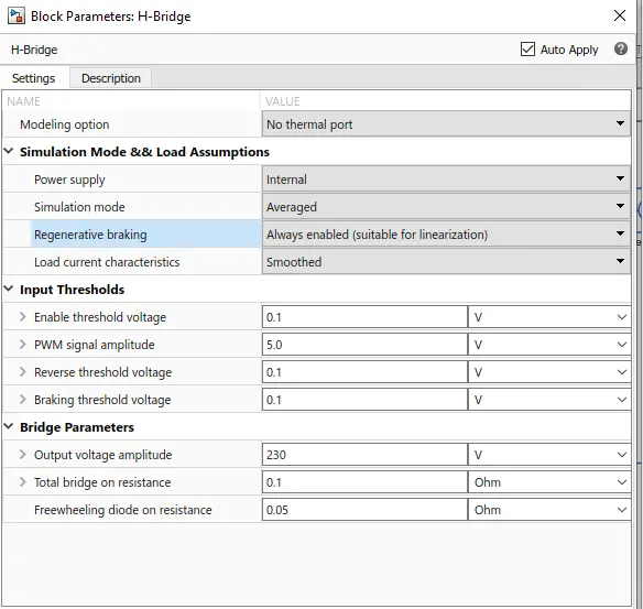
The H - Bridge Block parameters i considerd is shown below ,
2. Controlled PWM Voltage :-
- This Block is used to provide a controlled pulse width modulated voltage to the H - Bridge block.
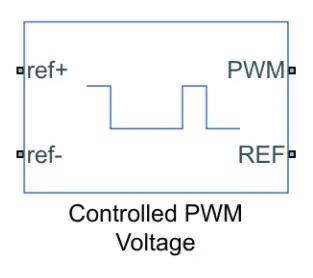
- This block creates a Pulse-Width Modulated (PWM) voltage across the PWM and REF ports.
- The output voltage is zero when the pulse is low, and is equal to the Output voltage amplitude parameter when high. Duty cycle is set by the input value.At time zero, the pulse is initialized as high unless the duty cycle is set to zero or the Pulse delay time is greater than zero.
- The Simulation mode can be set to PWM or Averaged. In PWM mode, the output is a PWM signal. In Averaged mode, the output is constant with value equal to the averaged PWM signal.
The parameters for this block were set as below :-
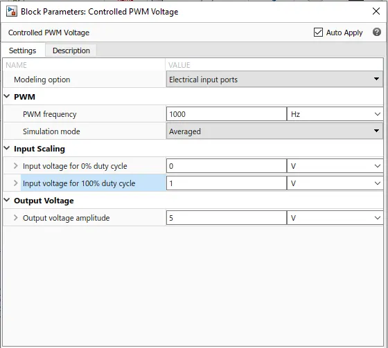
3. Controlled Voltage Source :-
- The input ports of the controlled PWM voltage block are still unconnected and that is because they require a controlled voltage source to provide the voltages to produce the voltage pulses to be fed in to the H-Bridge.
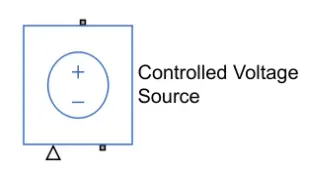
- For this, I have used the controlled voltage source block. This block is useful because it will provide the necessary voltage that is powerful enough to maintain the voltage at the output regardless of the current that passes through it.
This controlled voltage source block is shown below :-
4. Electrical Refrence :-
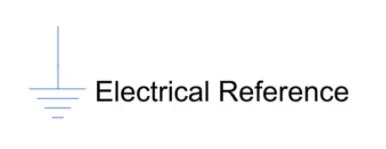
- This block is used to create grounding effect for the electrical circuit.
An electrical reference block is as shown below :-
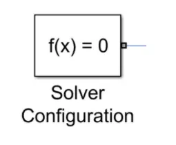
5. Solver Configuration :-
This block is used to solve necessary equation in any model ,
6. Current Sensor :-

- This block represents an ideal current sensor , that is a device which converts current measured in any electrical signal into physical signal prortional to current.
- Connection '+' and '-' are conserving electrical ports through which the sensor is inserted into circuit. Connection 'l' is a physical signal port that output is current value.
* Battery Subsyetm :-
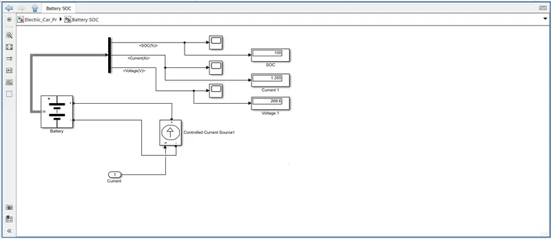
- This subsystem consist of a Battery of Lithium - Ion , A controlled current source , Demux . The port 1 is connected to the current sensor in the subsystem Power Converter.
The following image shows the battery system & current SOC arrangement :-
1. Battery Pack :-
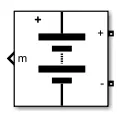
- Using this Battery block , the State of Charge (SOC) , Current & Voltage across the battery can also be calculated.
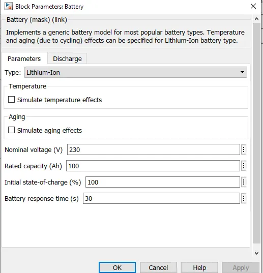
The battery Block Parameters ,
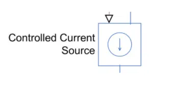
2. Controlled Current Source :-
- The controlled current source block is a part of the battery system used in the EV model. similar to the controlled voltage source , this block will represents an ideal current source that is powerful enough to maintain the specified current regardless of the voltage across it.
The controlled current source ,
3. Current Sensor :-
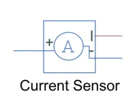
- The current sensor block represents an ideal current sensor and is used to convert the current measured in an electrical circuit to a physical signal that is proportional to the current.
- This block is used to measure the current between the battery circuit (controlled current source) and the DC motor.
The current sensor block is shown below:-
* Vehicle :-
Vehicle subsystem contain follwing Arrangement ,
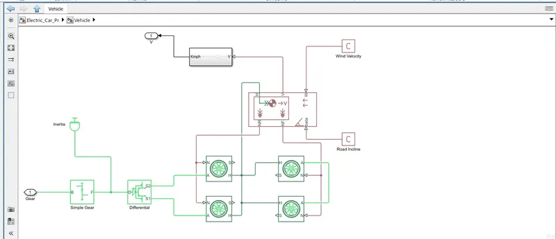
1. Vehicle Body Block :-
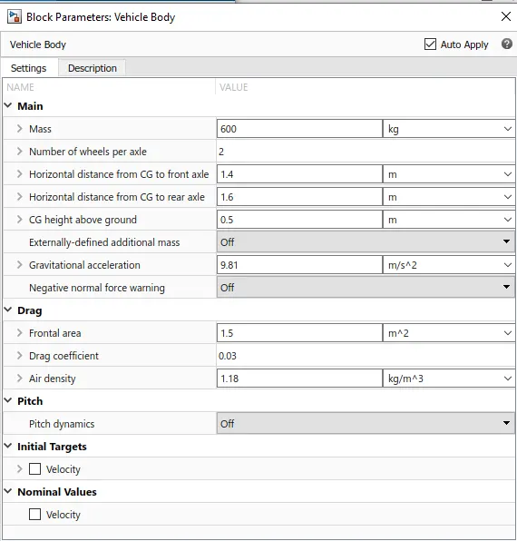
In this model we have to first add the vehicle body block ,
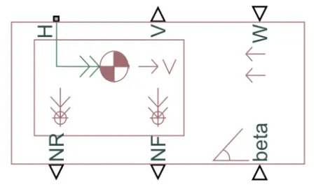
- This Block contains 6 ports :
- H - This stands for'HUB' & it is used to connect the hubs of wheels to the main body of the vehicle.
- V - This is a physical signal output port which stands for 'Velocity' & is used to output the speed / velocity at which the vehicle is moving.
- W - This is physical signal input port & allows us to model a 'Headwind' acting on the vehicle by giving a speed for it.
- NR - This is a physical signal output port to model the rear wheel normal forces.
- NF - This is a physical signal output to model the front wheel normal forces.
- beta - This is a physical signal input port & allows us to model the vehicle on an inclination angle to create the effect of a hill climbing force.
Now we need to define Vehicle Body Blocks parameters :-
2. Tyres :-
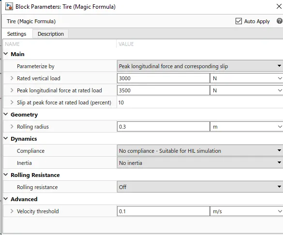
- The tyres used in this EV model are 'Magical Formula Tires'. There are several tyre blocks can be used for EV modelling but i have used the magical formula ones because it allows us to model the longitudinal behavior of tyres on highways. They also allow us to take into consideration extras such as tyre inertia , Stiffness , etc which helps in better accuracy of real world conditions.
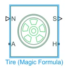
In above image we can see that it has 4 ports & they are:-
- N - This port stands for 'Normal' & is the physical signal input port for the normal force acting on the tire & is considered positive in the downwards dirrection.
- S-This port stands for ‘Slip’ and is the physical signal output port is that reports the slip acting on the tire.
- A- This port stands for ‘Axle’ and is the mechanical rotational conserving port for the wheel axle.
- H- This port stands for ‘Hub’ and is the mechanical translational conserving port for the wheel hub through which the thrust developed by the tires is applied to the vehicle body.
Now onto the Tyre Parameters, I have considered the following values :-
3. The Simple Gear :-
- Here I have chosen 'Simple Gear' block as to simplify the transmission system parameters.
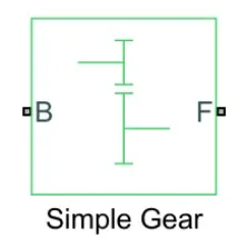
- This block models a gear system with a fixed gear ratio and with no inertia effects, however we can modify the effects of meshing of gear teeth.Connections B (base) and F (follower) are mechanical rotational conserving ports.
- Specify the relation between base and follower rotation directions with the Output shaft rotates parameter. Optionally include thermal effects and expose thermal conserving port H by setting Friction model to a temperature-dependent setting.
The simple gear block is as shown below :-
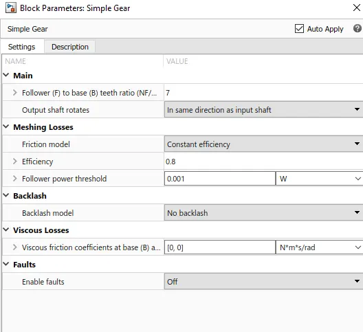
Prameters of Gear :-
4. Inertia Block :-
- An inertia block has been added to the workspace to provide an ideal mechanical rotational inertia for the simple gear block.
- This block has only one mechanical rotational conserving port and the positive direction of the block is from the port to the reference point which would be the simple gear in this case.
- The inertia torque acts in the positive direction is the inertia is accelerated in the positive direction.
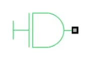
The inertia block is shown below:-
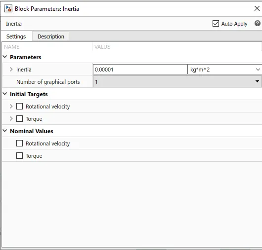
The inertia block parameters :-
5. Wind and Slope :-
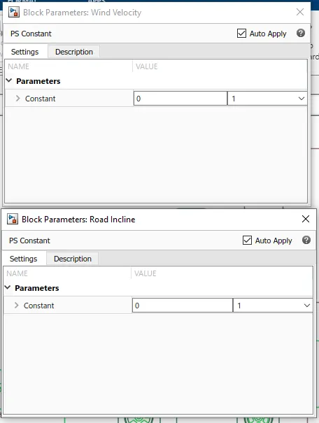
Both wind & slope are considerd as constant blocks & parameters are shown below :-
6. Velocity Subsytem :-
- The velocity port which outputs the velocity signal of the vehicle body block has been modified. By default, the velocity signal that is output from the vehicle body block is measured in miles per hour.
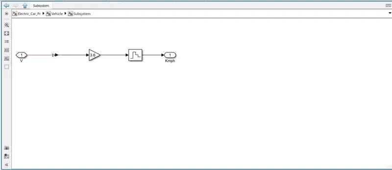
- To change these units, I have implemented a small subsystem from the output of the velocity port.
This subsystem uses the following blocks:-
- PS- Simulink converter - this block will convert the physical signal of velocity to a logic signal.
- Gain - This block uses a multiplication factor of 3.6 to convert the miles per hour units to kilometres per hour.
- Zero - Order Hold - This block is used implement a zero order hold sample period.
The subsystem is as follows :-
7. Differntial Block :-
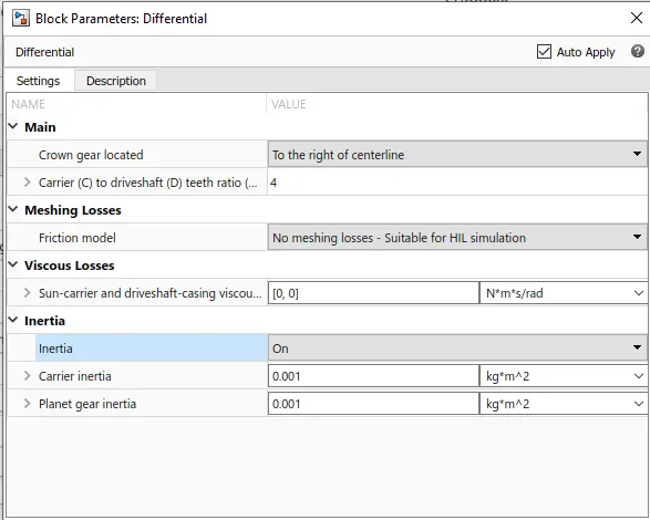
- Represents a differential which is arranged as a planetary bevel gear train equipped with an additional bevel gear transmission between the driveshaft and the carrier.
- The pinion gear of this transmission is attached to the driveshaft while the large bevel crown gear is affixed to the carrier. Compliance is not modeled in this block. Optionally include inertia and losses from gear meshing and viscous bearing friction.
- Connections D, S1, and S2 are mechanical rotational conserving ports associated with the driveshaft and the two output shafts, respectively.
- S1 and S2 are the shafts belonging to the two sun gears. When there is no relative slippage across the differential, ports S1 and S2 both rotate in the positive direction when port D rotates in a positive direction if the crown gear is located to the right of centerline. Optionally include thermal effects and expose thermal conserving port H by setting Friction model to a temperature-dependent setting.
The Following Blocks are used to calculate the speed & the distance travelled by the vehicle :-
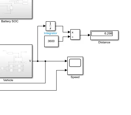
so at the end of FTP75 drive cycle , the total distance travelled by vehicle is 6.298 Km.
Results :-
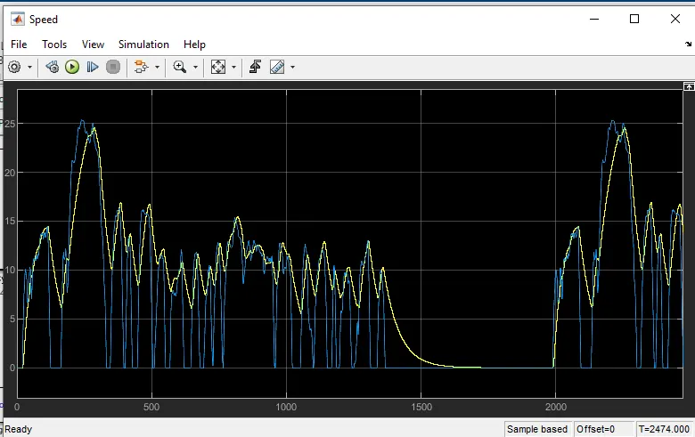
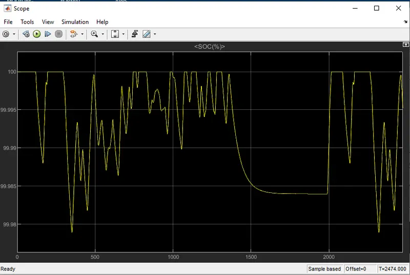
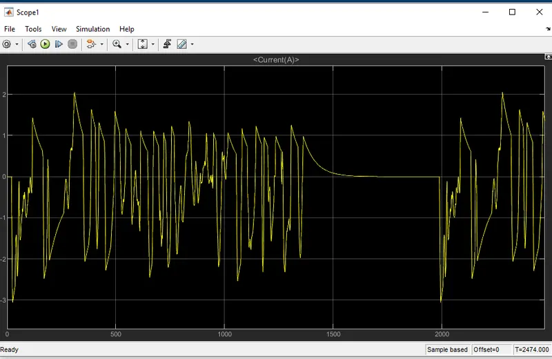
The model was run for 2474 Seconds & below results are shown ,
1. SPEED SCOPE :
2. SOC :
At the end of drive cycle (i.e. after 2474 seconds) the SOC is arround 99.99%.
3. Current :
4. Voltage :
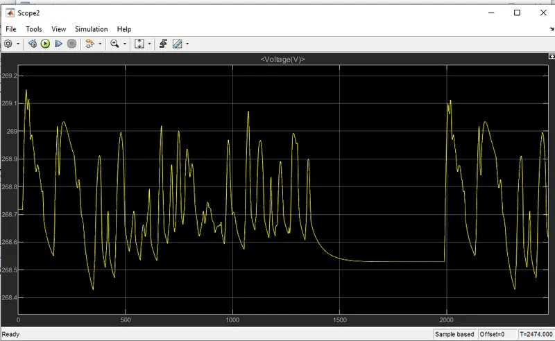
Conclusion :-
- The EV model has been created with the necessary block components using the SIMULINK software and the model has been simulated for a customized FTP75 drive cycle.
- The simulation has produced results of the velocity of the vehicle, current and voltage flowing from the battery, and the SOC of the battery as well as the distance travelled by the EV.
- Since the EV model was parameterized to simulate averaged voltage pulses in the H-Bridge and Controlled PWM voltage blocks to be fed in to the DC motor, the simulation finished very quickly within a matter of seconds.
- The EV model was able to follow the commands given by the reference velocities from the drive cycle data,although it could have followed the reference signals more closely.