Week-7 Challenge: DC Motor Control
1.MATLAB demo model named ‘Speed control of a DC motor using BJT H-bridge:-
BJT H-Bridge :-
- An H-Bridge is an arrangement of transistors that allows a circuit full control over a standard electric DC motor. That is, an H-bridge allows a
microcontroller, logic chip, or remote control to electronically command the motor to go forward, reverse, brake, and coast.
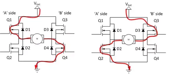
- H-bridge is an electronic circuit that switches the polarity of a voltage applied to a load. These circuits are often used in robotics and other
applications to allow DC motors to run forwards or backwards.
IGBT :-
- The insulated gate bipolar transistor (IGBT) is a semiconductor device with three terminals and is used mainly as an electronic switch. It is characterized by fast switching and high efficiency, which makes it a necessary component in modern appliances such as electric cars and variable frequency drives
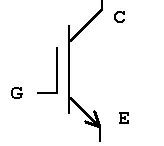
- Its ability to turn on and off, rapidly, makes it applicable in amplifiers to process complex wave-patterns with pulse width modulation. It
integrates an isolated gate using Field Effector Transistor to obtain a control input.
*SIMULATION :-
- The Bipolar Junction Transistor (BJT) when used for power switching applications, operates as an IGBT. When it is conducting (BJT operating
in the saturated region), a forward voltage Vf is developed between collector and emitter (in the range of 1 V). Therefore, the IGBT block can
be used to model the BJT device.
- The IGBT block does not simulate the gate current controlling the BJT or IGBT. The switch is controlled by asignal. The DC motor uses the
preset model (5 HP 24V 1750 rpm). It simulates a fan type load (where Load torque is proportional to square of speed).
- The H-bridge consists of four BJT/Diode pairs (BJT simulated by IGBT models).
- Two transistors are switched simultaneously as Q1 and Q4 or Q2 and Q3. When Q1 and Q4 are fired, a positive voltage is applied to the
motor and motor runs in forward motion.When Q2 and Q3 are fired, a negative voltage is applied to the motor runs in the reverse direction.
Model Named Speed Control of DC Motor Using BJT H-Bridge ,
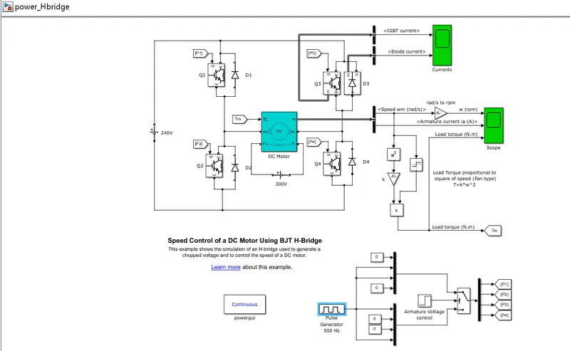
- The Pulse gnerator given by a pulse width of 75% and period of 2e-3 seconds.The motor parameters of the torque and field voltage and
armature voltages are taken as default values of the model.
The output waveforms of the diode current and IGBT current from the current scopes are shown below ,
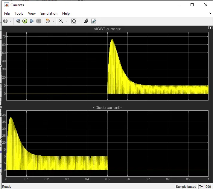
- From above waveform we observed that form 0 - 0.5 time IGBT current is zero and the diode current is on or starts to flow now.
Output waveform of load Torque , Armature current and speed is given by ,
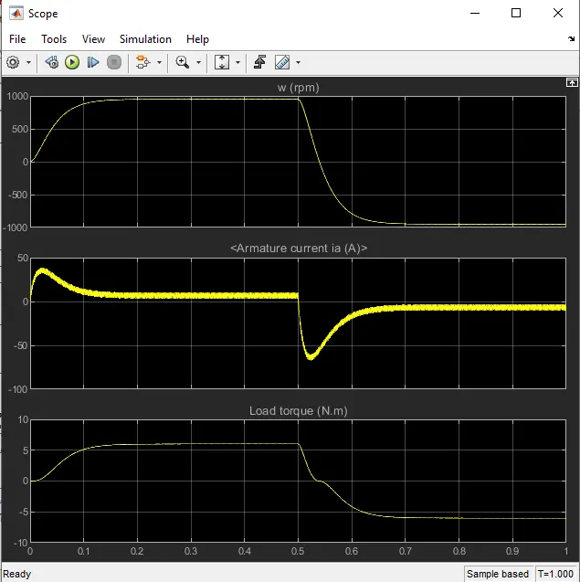
The output Waveform with 50% ,
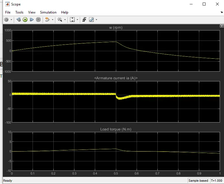
- Graph of pulse width with 50%.
- From above graph the Armature current shoot-up at the starting armature current there is sudden rise in waveform it is noticed. To reduced sudden rise in armature current we will reduced the duty cycle of PWM to 75% - 50%.
1-C. Refer to the help section of ‘The Four-Quadrant Chopper DC Drive (DC7) block’. Compare it with the H-bridge model:-
- The Four-Quadrant Chopper DC Drive (DC7) block represents a four-quadrant, DC-supplied, chopper (or DC-DC PWM converter) drive for DC motors. This drive features closed-loop speed control with four-quadrant operation. The speed control loop outputs the reference armature current of the machine. Using a PI current controller, the chopper duty cycle corresponding to the commanded armature current is derived.
- This duty cycle is then compared with a sawtooth carrier signal to obtain the required PWM signals for the chopper.
- The main advantage of this drive, compared with other DC drives, is that it can operate in all four quadrants (forward motoring, reverse regeneration, reverse motoring, and forward regeneration). In addition, due to the use of high switching frequency DC-DC converters, a lower armature current ripple (compared with thyristor-based DC drives) is obtained. However, four switching devices are required, which increases the complexity of the drive system.
Simulink Model for DC7 block :-
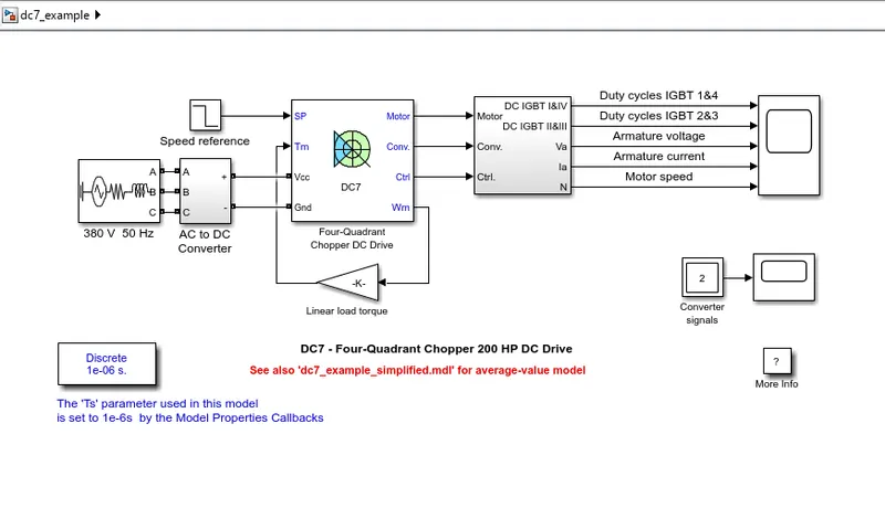
- The 200 HP DC motor is separetly excited with constant 150 V DC field voltage source. The armature voltage provided by an IGBT converter controlled by 2 PI regulators.The converter is fed by 515 V DC bus obtained by rectification of 380 V AC 50 HZ voltage source.
- In order to limit DC bus voltage during dynamic braking mode,a braking chopper has been added between the diode rectifier & the DC7 block.
- The first regulator is a speed regulator , followed by a current regulator.The speed regulator outputs the armature current reffrence (in p.u) used by current controller in order to obtain the electromagnetic torque needed to reach the desired speed.
For proper sysytem behaviour, the instantaneous pulse values of IGBT devices 1 & 4 are opposite to those of IGBT device 3 & 4. This generates the average armature voltage needed to obtain the desired armatire current in order to limit amplitude of the curent oscillations , a smoothing inductance is placed in series with the armature ckt.
Comparision of Four Quadrant Chopper & H-Bridge Model ,
| Sr.no | Four Quadrant chopper | H-bridge model |
| 1. | The motor can be operated in all the four different modes (forward motoring,reverse motoring ,forward braking and reverse braking). | In this model we have only two modes of operation forward and reverese by changing the direction of motor. |
| 2. | In this the vehicle control is better. | In this the vehicle control are less. |
| 3. | Regenerative braking can be achieved. | In this regenerative braking is not possible. |
| 4. | The signals given to the four quadrant operation are discrete. | Here the signals are continuous. |
| 5. |
The four-quadrant chopper widely used in the automobile application for the control of DC motor speed and direction. |
The H-bridge is used in the robotics and electro-mechanical devices to control the speed and direction of the DC motor at low level speed. |
| 6. |
In H-bridge we need to change polarity which turns into opposite direction to control the motor. |
In chopper model we need to interrupt one signal under control of another. |
2. Develop a 2-quadrant chopper using simulink & explain the working of the same with the relevant results:-
Simulink Model ,
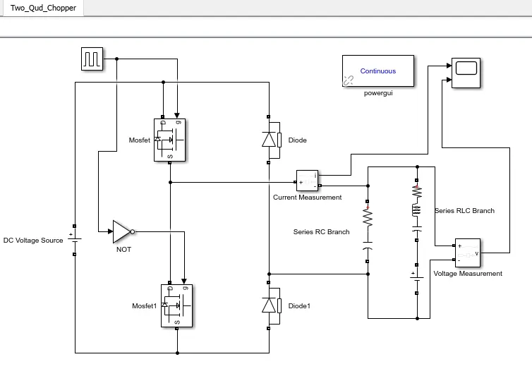
- The metal-oxide semiconductor field-effect transistor (MOSFET) is a semiconductor device controllable by the gate signal (g > 0).
- The diode is a semiconductor device that is controlled by its own voltage Vak and current Iak. When a diode is forward biased (Vak > 0).
- The Current Measurement block is used to measure the instantaneous current flowing in any electrical block or connection line. The Simulink output provides a Simulink signal that can be used by other Simulink blocks.
- The Voltage Measurement block measures the instantaneous voltage between two electric nodes. The output provides a Simulink signal that can be used by other Simulink blocks.
- The Pulse Generator block generates square wave pulses at regular intervals. The block waveform parameters, Amplitude, Pulse Width, Period, and Phase delay, determine the shape of the output waveform.
- The DC Voltage Source block implements an ideal DC voltage source. The positive terminal is represented by a plus sign on one port. You can modify the voltage at any time during the simulation.
- The Logical Operator block performs the specified logical operation on its inputs. An input value is true (
1) if it is nonzero and false (0) if it is zero. - Here RC Filter is used to reduce the distortion in the waveform.
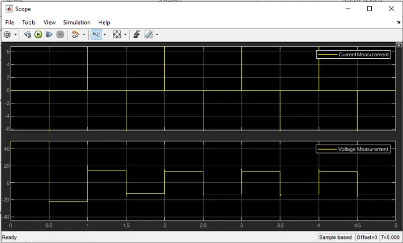
Output waveform of 2-quadrant chopper :-
3. Explain in a brief about operation of BLDC motor - :
- Brushless DC motors (BLDC) have been a much focused area for numerous motor manufacturers as these motors are increasingly the
preferred choice in many applications, especially in the field of motor control technology. BLDC motors are superior to brushed DC motors in
many ways, such as ability to operate at high speeds, high efficiency, and better heat dissipation.
- They are an indispensable part of modern drive technology, most commonly employed for actuating drives, machine tools, electric '
propulsion, robotics, computer peripherals and also for electrical power generation. With the development of sensorless technology besides
digital control, these motors become so effective in terms of total system cost, size and reliability.
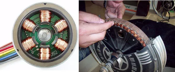
- A brushless DC motor (known as BLDC) is a permanent magnet synchronous electric motor which is driven by direct current (DC) electricity
and it accomplishes electronically controlled commutation system (commutation is the process of producing rotational torque in the motor by
changing phase currents through it at appropriate times) instead of a mechanically commutation system. BLDC motors are also referred as
trapezoidal permanent magnet motors.Unlike conventional brushed type DC motor, wherein the brushes make the mechanical contact with
commutator on the rotor so as to form an electric path between a DC electric source and rotor armature windings, BLDC motor employs
electrical commutation with permanent magnet rotor and a stator with a sequence of coils. In this motor, permanent magnet (or field poles)
rotates and current carrying conductors are fixed.
- The armature coils are switched electronically by transistors or silicon controlled rectifiers are correct rotor position in such a way that
armature field is in space quadrature with the rotor field poles. Hence the force acting on the rotor causes it to rotate. Hall sensors or rotary
encoders are most commonly used to sense the position of the rotor and are positioned around the stator. The rotor position feedback from
the sensor helps to determine when to switch the armature current.
- This electronic commutation arrangement eliminates the commutator arrangement and brushes in a DC motor and hence more reliable and
less noisy operation is achieved. Due to the absence of brushes BLDC motors are capable to run at high speeds. The efficiency of BLDC
motors is typically 85 to 90 percent, whereas as brushed type DC motors are 75 to 80 percent efficient. There are wide varieties of BLDC
motors available ranging from small power range to fractional horsepower, integral horsepower and large power ranges.
- Construction of BLDC Motor :-
- BLDC motors can be constructed in different physical configurations. Depending on the stator windings, these can be configured as single-
phase, two-phase, or three-phase motors. However, three-phase BLDC motors with permanent magnet rotor are most commonly used.
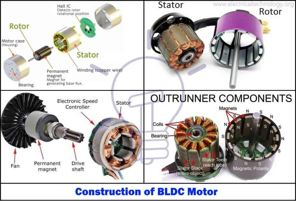
- Stator of a BLDC motor made up of stacked steel laminations to carry the windings. These windings are placed in slots which are axially cut
- Advantages of BLDC Motor :-
- It has no mechanical commutator and associated problems. High efficiency due to the use of permanent magnet rotor.
2.High speed of operation even in loaded and unloaded conditions due to the absence of brushes that limits the speed.
3.Smaller motor geometry and lighter in weight than both brushed type DC and induction AC motors.
4. Long life as no inspection and maintenance is required for commutator system.
- Disadvantages of BLDC Motor :-
- These motors are costly.- Electronic controller required control this motor is expensive.
- Not much availability of many integrated electronic control solutions, especially for tiny BLDC motors.
- Requires complex drive circuitry.
- Need of additional sensors.
- Applications of BLDC Motor :-
- Computer hard drives and DVD/CD players.
- Electric vehicles, hybrid vehicles, and electric bicycles.
- Industrial robots, CNC machine tools, and simple belt driven systems.
- Washing machines, compressors and dryers.
- Fans, pumps and blowers.
Conclusion :-
- From Question 1 MAtlab demo model for speed control of DC motor using BJT H-Bridge is done with help of varrying duty cycle the Armature current , Torque & Speed can be controlled.
- From Question 1.C the DC7 block is compare with H-Bridge ,
duty cycle is compared with swatooth carrier signal to obtained a requre PWM signal for chopper.
- From Question 2 the Two Quadtrant Chopper Model is obtained with the help of output waveform it is clear that output of Current dirrection is Negetive & voltage waveform is Positive half cycle.
- In Question 3 Explaination about Brush-less DC motor studdied the construction , Advantages of BLDC motor , & Application of BLDC motor.