Final Project: Design of an Electric Vehicle
Create a MATLAB model of electric car which uses a battery and a DC motor. Choose suitable blocks from Powertrain block set. Prepare a report about your model including following:
Objectives:
1. System level configurations
2. Model parameters
3. Results-
4. Conclusion
Refer to the article: Modeling of Vehicle Body and Tires : Skill-Lync
Explaination : Final Project
Introduction:
An Electric Vehicle (EV) is a vehicle that uses one or more electric motors for propulsion. Electric Vehicle likely to be an alternative energy mode of transportation for the future as it has shown a great ability to reduce the consumption of petroleum based and other high CO2 emitting transportations fuels. The vision of electrified transportation is the perfect combination of renewable energy sources and battery electric vehicles. It promises zero greenhouse gas emissions without using petroleum or other fossil fuels. The adoption of electric vehicles is expanding across consumers, commercial, industrial and public sectors which represent opportunities for electric utilities. One crucial point for the electric vehicle market to succeed is to focus on research and development to model and develop the battery technology, motor efficiency, vehicle dynamics and transmission performance.
Modelling of electric vehicles helps in the design, analysis and implementation phases. The aspects that need to be modelled include vehicle dynamics, transmission performance and battery of the electric vehicles to acquire the power requirements of the storage system.
Block Diagram of Electric Vehicle
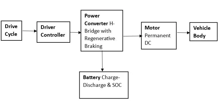
We have vehicle body then will take up a motor and the vehicle body and before connecting the battery still consider connect the motor to the vehicle system and the vehicle body and before connecting the battery directly to the motor. We will require motor controller to change the speed of the vehicle. If we directly connect the battery to the motor will run to the rated speed and there is no any control over the vehicle so we want the control to happen and that is possible by a power converter. Power converter is nothing but H-Bridge with Regenerative braking feature, so we connect a battery will give supplied to the Power Converter. Power Converter will actually change the speed of the vehicle. So, the basic arrangement of the electric vehicle. We want to run this model for the given input. So, we need to have a throttle and brake pedal in our hand that is nothing but the drive cycle input. If we decide that at what speed wee want to run vehicle to give the drive cycle input that is at what speed we want to run our vehicle. So, the Drive cycle input and there is a Driver controller which actually track the actual speed of the vehicle and match with the given input.
System level Configuration:
we have to create Electric Vehicle Model in the Simulink for that we need to model using individual component which can we browse in the Simulink Library Browser add each Simulink Block and Simscape Block connection according to model and configure its parameter as per our requirement of the model.
The Blocks are used for to create
Simulink Block
Scope, Integrator, Multiport switch, Constant, Divide, Display, From Spreadsheet, Signal Builder, Bus Selector
Simscape Block
Tires, Vehicle body, Gears, Inertia, DC motor, H-Bridge, Controlled PWM voltage source, Battery.
Powertrain Blockset
Drive cycle source, Longitudinal driver.
Vehicle Body
First start with the vehicle body as shown below:
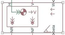
This block contains six ports which is used to make a model
H - It is stands for 'Hub' and it is used to connect the Hubs of the wheels to the main body of the vehicle.
V - Physical signal output port for vehicle longitudinal velocity in the vehicle reference frame.
W - Physical signal input port for headwind speed
NR - Physical signal output port for normal wheel force on the Rear axle.
NF - Physical signal output port for normal wheel force on the front axle.
beta - It is a Physical signal input port for road inclination angle and allow.
Double click on the Vehicle Body change its Parameter:
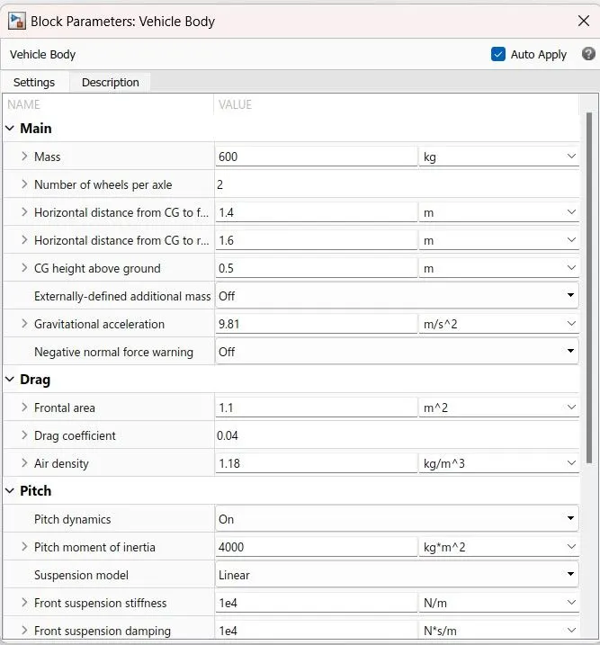
Mass drecease from 1200 to 600 in kg it is four wheel Electric Vehicle it has 2 numberber of wheels per axle we switch on the Pitch Dynamic and changed the Drag parameter Drag coefficent decrease 3 - 1.1, Drag coefficent - 0.4 - 0.04
other parameter are remaining same.
Tire
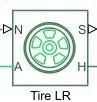
Here, we can see that it 4 ports.
N - N is stands for Normal Force. It is a physical signal input port that applies the normal force acting on the tire. The force is considered positive if it acts downwards.
H - H is stands for Hub. It is the mechanical translational conserving port for the wheel hub through which the thrust developed by the tire is applied to the vehicle.
S - S is stands for Slip. It is a physical signal output port that reports the tire slip.
A - A is stands for Axle. It is the mechanical rotational conserving port for the wheel axle.
Double clicking the Tire magic formula and set the tire parameter.
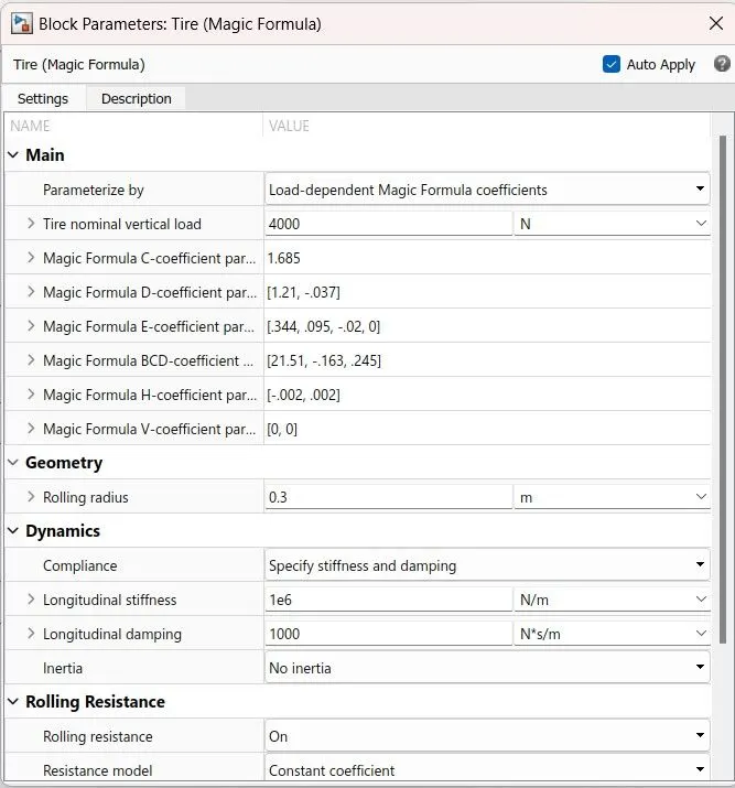
So we get window like shown below i.e vehicle related parameter is according to various whether you want take a peak longitudinal forces and slip or constant formulas where you have BCD coefficient or Load dependent magic formula coefficients so based on the tire magic formula theory here we can put up al and the things we have rolling radius, we can select about Dynamics, we can specify what is the stuffiness and the damping and we can select the Rolling Resistance.
Gear
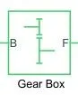
It is a Simple Gear block from Simscape library it has two Connections B (base) and F (follower) are mechanical rotational conserving ports. Specify the relation between base and follower rotation directions with the Output shaft rotates parameter.
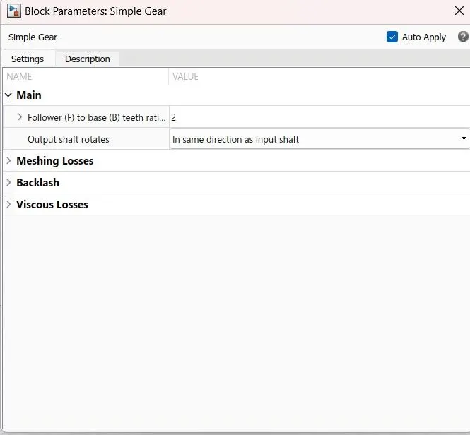
Here, we changed the simple gear parameter in which Output shaft rotates - in opposite to the input shaft to in same direction of the input shaft.
Inertia Block
The block has one or two mechanical rotational conserving ports. The inertia torque is positive if the inertia is accelerated in the positive direction.
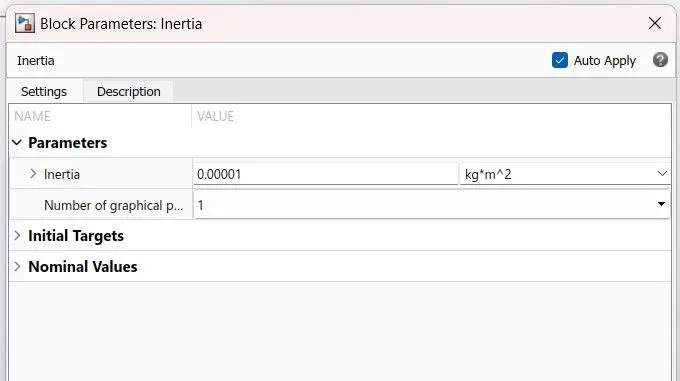
Double click on the inertia block we change inertia value 0.01 to 0.00001 kg*m^2, to smooth Performance of the Vehicle.
PS constant

The PS Constant block generates a physical signal of a constant value. The Constant parameter accepts both positive and negative values. The block output is a physical signal port.
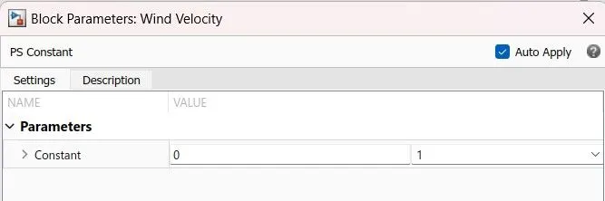
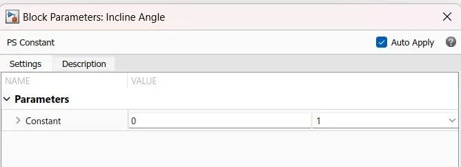
Add two PS- constant block to connect them to the wind velocity (W) and road inclination (beta) of the Vehicle body block. Here we are the vehicle flat surface there angle inclination.
PS Terminator

PS Terminator can be used to indicate that the signal to terminate physical signal outputs connection.
If it is not connected physical signal output ports it generate warnings.
Inside the Vehicle Body Subsystem:
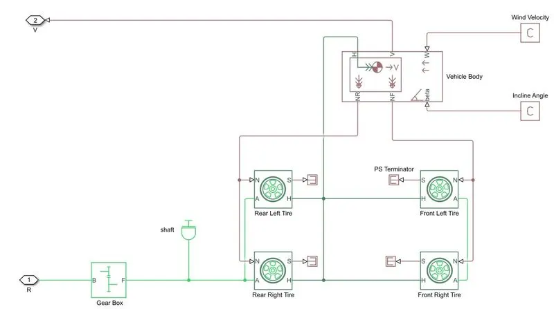
In the Matlab Simulink window we have to take Vehicle body. we want to make a four-wheeler so need to have four such tires. left hand side are Rear axle wheel and Right hand side Front axle wheel. Let's this make to Rear wheel drive. we are going to connect the power of the motor shaft of the motor through the transmission system to the Rear Axle. we have Tire (Magic Formula) which has 4 ports H is stands for Hub, A is stands for Axle, S is stands for tire slip, N is stands for Normal force which is applied to the Tire. So the vehicle body is going to installed above the Tires blocks where we are connect this vehcle body to the tire ports in order to coonect them. Connect all Hub terminals of tires and vehicle body together RL, RR, FL,FR (Rear Right, Rear Left, Front Left, Front Right).
The simple gear block is connected at Rear Axle of the Tire. The DC motor Rotational Shaft is connected to Base connection of the simple gear box through the Rotational 'R' port. In this we don't have provide any input to wind velocity PS-constant and Road inclination PS-constant. Velocity output of the Vehicle Body is given to 'V' Port remains open inside the subsystem to Measured the Distance traveled by Electric car.
we can create wind velocity input to the Vehicle body and we can also assined here the vehicle inclination angle, But we are not provide wind velocity and road inclination angle.
Subsystem of Vehicle
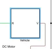
We can see there is a block name Subsystem, instead of having mulitle number of block we can enter into one common block, we created a subsystem two inputs on the Vehicle R and V.
DC Motor
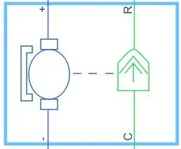
This block represents the electrical DC motor. here we take a very simple motor which is a Brushless type DC motor. so this brush type DC motor where you can see there is an Electrical and Mechanical combination. here R is stands for Rotor and C for the casing and this is a Mechanical part which is green and the blue one is Electrical part, where you need to connect the output power converter to this motor terminals. Let's R connector of the DC motor connect to B (base) of the Gear Box, and we have connected the shaft of the DC motor to the gear box. now casing is the fixed part of the motor has to connected to Mechanical Rotational reference frame. The rotor will rotates with the reference to this portion.

we will pefer that you use a very simple permanent magnet DC motor so in this DC motor we can actually choose the parameters by the rated power, rated speed and the no load speed. So usually the power rating of the DC motor used for an electric car 50 KW. to 100KW. change the units W to KW.
Assign the Rated load (Mechanical Power) - 50 kilowatts and according to the vehicle speed and the gear ratio we have to choose the rated speed of the motor. So Rated speed of the motor ( at rated load) - 5000, No-load speed is applied - 8000 rpm. and the Rated DC supply is give to 300 V why because of this motors are of high power and they are high voltage obiviously so you can have 100 number of cells connected in series each of three volt or 3.6 volt per cell will end up having around 300 to 400 DC bus voltage
Power Converter:
If we are going to control the DC motor so the DC motor can be controlled by DC-DC converter. The converter is going tp have one input terminal from the battery and output terminals to the battery, which is different DC levels, if we directly connect battery to the DC motor. we will lose any control over the vehicle Acceleration and Breaking effect. whatever is a amount of energy available in the battery and the motor power.
Instead of DC-DC converter we canactually have one H-Bridge which is combination of four number of switches, if we change the model to the external
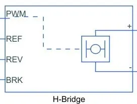
Going to place and to connect the positive terminal with the positive of the motor negative to of the motor. We have a PWM controlled DC motor Drive so look at the inputs where the inputs are PWM, Reverse, Reference and Break this are the four control inputs. Connect the battery over the PWM block.
This block represents an H-bridge motor drive. The block can be driven by the Controlled PWM Voltage block in PWM or Averaged mode. In PWM mode, the motor is powered if the PWM port voltage is above the Enable threshold voltage. In Averaged mode, the PWM port voltage divided by the PWM signal amplitude parameter defines the ratio of the on-time to the PWM period. Using this ratio and assumptions about the load, the block applies an average voltage to the load that achieves the correct average load current. The Simulation mode parameter value must be the same for the Controlled PWM Voltage and H-Bridge blocks.
If the REV port voltage is greater than the Reverse threshold voltage, then the output voltage polarity is reversed. If the BRK port voltage is greater than the Braking threshold voltage, then the output terminals are short circuited via one bridge arm in series with the parallel combination of a second bridge arm and a freewheeling diode. Voltages at ports PWM, REV and BRK are defined relative to the REF port.
If exposing the power supply connections, the block only supports PWM mode.
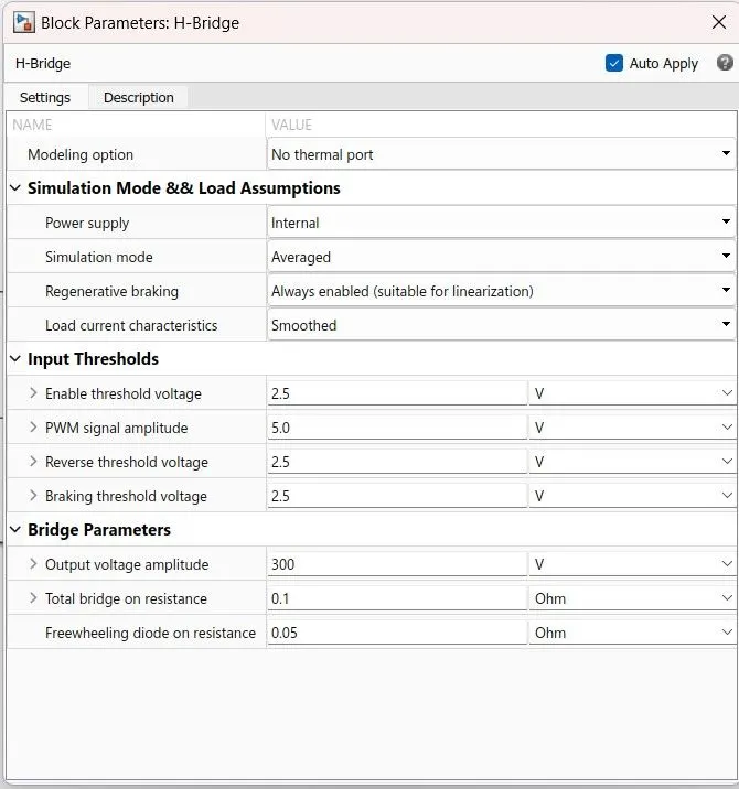
Double on the H-Bridege Block and change the parameter,
Default Change
Power supply - Internal Internal
Simulation mode - PWM Averaged
Freewheeling - via one semiconductor switch and one freewheeling diode.
Regenrative braking - Always enabled (suitable for Linearization)
Load current characteristics - Smoothed
In Bridge Parameters
Output voltage amplitude - 12 V 300 V
H-Bridge can be configured in multiple number of ways where keep it internal then it can make the simulation mode as PWM or Average the moment make this as PWM. The simulation time is going to increase drastically if we want ot run this model for five seconds, it is good but the Drive cycle on actual runtime of the vehicle is going to be in munitues or may be in hours, so that select the average mode where similar simulation run comparatively faster and let enable the Regenerative Braking and keep the load current characteristics as smooth
In the input theroshold to keep the default values but we can change theroshold voltage, PWM signal Amplitude, it is possible to have a Reverse connection or we want to rotate this motor in the reverse direction that is possible. if we want to apply breaking that also possible and here we need to give the output voltage amplitude which is similar to the voltage. we have selected for the motor and we need to decide about the losses happening inthe bridge switches along with the Diodes so this is we can configure about H-Bridge.
Let's keep this internal and averaged enable smoothed.
we are not connecting any Battery in case of an Internal power supply because this bridge will take the Power ON, its own ON from its own DC source. So connect now positive over positive of the DC motor and Negative over Negative of the DC motor.
Controlled PWM Voltage:
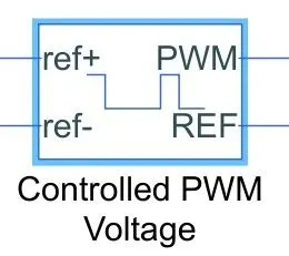
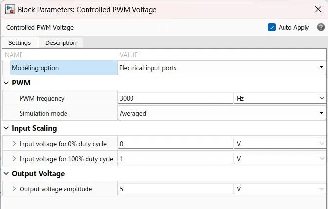
Here we are going to control the PWM so we ned to controlled PWM voltage so this is a controlled PWM voltage block where we will connect the PWM with input PWM line. you can see this block will actually apply pulses and based on this pulses from the fixed Battery Voltage will be available to the Motor and the Motor speed and Motor torque are going to change so reference to connecct to the reference part and Let's to explore the reverse aspect so let connect it with the ground.
So the ground is a nothing but Electrical reference. Let's the 'ref -' and REF of the Controlled PWM Voltage also grounded as the electrical reference connect.
'ref+' Now this connection is actually the controller's port. At this point it need to apply the controllers input. So controllers input is going to be applied at this port, which is comming from Controlled Voltage Source.
Controlled Voltage Source
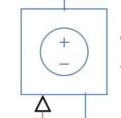
The block represents an ideal voltage source that is powerful enough to maintain the specified voltage at its output regardless of the current passing through it. The output voltage is V = Vs, where Vs is the numerical value presented at the physical signal port.
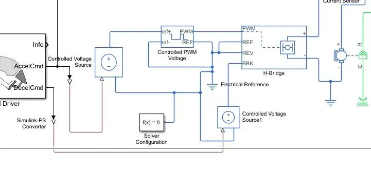
Positive of the Controlled Voltage Source is connect to ref+ of the Controlled PWM Voltage.
and Another Controlled Voltage Source positive connect to the Break of the Controlled PWM voltage, so we want to use the Regenerative braking.
whenever the vehicle speed is going to reduce the power can can flow back to the Battery and battery will get charged so DC motor will act as a Generator for shorter Duration of time and it will feed the Battery back with a negative current or the current flowing into the positive terminal of the Battery. So we have controller is Ready.
In Controlled Voltage Source has three ports Positive , Negative and Physical signal port. Both Controlled Voltage Source physical signal input port is connected to Longitudinal drver block one is connected to Accel CMD and another is connected to DECL CMD.
There is a another control pulse applied between 0 to 1. we can apply signal over for acceleration and another signal connect to Break paddleis applied.
If we apply the Acceleration signal to the PWM part which will increase the speed of the motor, if we apply Brake input is connected with the brake port of the H-Bridge and this will redduce the speed of the motor or it will apply the Regenerative Brakes.
Current sensor:

The block represents an ideal current sensor, that is, a device that converts current measured in any electrical branch into a physical signal proportional to the current.
Connections + and - are conserving electrical ports through which the sensor is inserted into the circuit. Connection I is a physical signal port that outputs current value.
Power Supply Section:
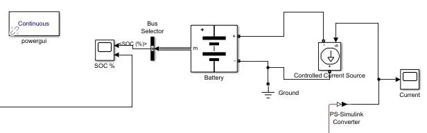
Battery

Usually, Vehicle that can be powered by an electric motor that draws electricity from a battery for propulsion.
The state of charge (SOC) for a battery is a measure of battery's charge, expressed as a percent of the full charge. The depth of discharge (DOD) is the numerical compliment of the SOC, such that DOD = 100% - SOC.
For example, if the SOC is:
-
100% — The battery is fully charged and the DOD is 0%.
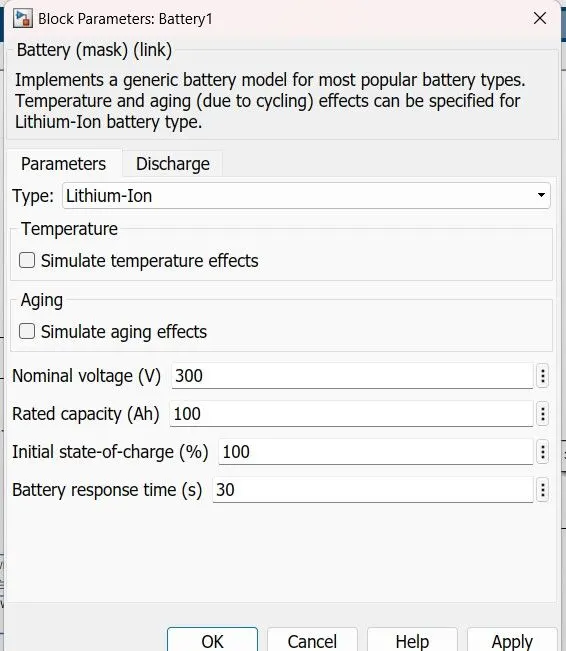
Controlled current Source

Converts the Simulink input signal into an equivalent current source. The generated current is driven by the input signal of the block.
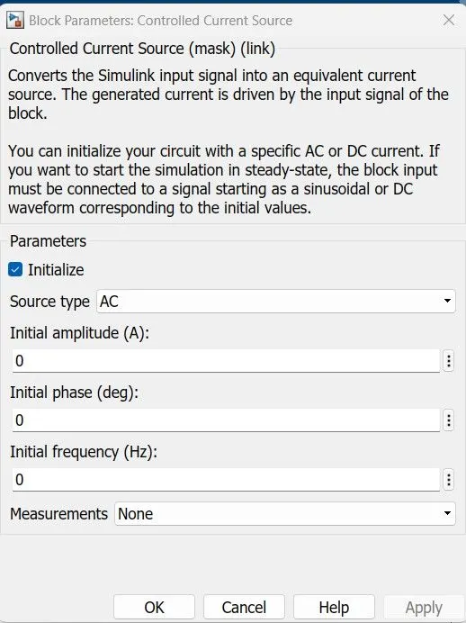
You can initialize your circuit with a specific AC or DC current. If you want to start the simulation in steady-state, the block input must be connected to a signal starting as a sinusoidal or DC waveform corresponding to the initial values.
Bus selector
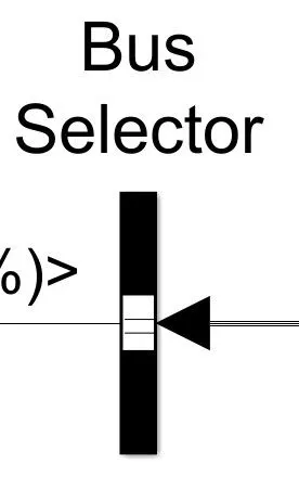
The Bus Selector block outputs the elements you select from the input bus. The block can output the selected elements separately or in a new virtual bus.
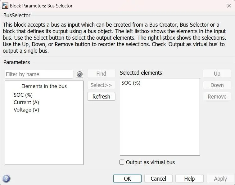
Here we want to observe the state of charge a percent of Battery charge, so because we select the SOC%.
PowerGui Block
The powergui block allows us to choose one of these methods to solve our Model:
-
Continuous, which uses a variable-step solver from Simulink
-
Discretization of the electrical system for a solution at fixed time steps
-
Continuous or discrete phasor solution
Powertrain Blockset:
Powertrain Blocks provides fully assembled reference application models of automotive powertrains.
Longitudinal Driver:
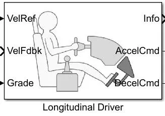
Whatever output comming from the Multiport switch Driver. The Driver is constantly variation or the break command so how can convert the Acceleration commands. so we require a controller for that, and the controller which is nothing but a driver is the lonngitudinal driver looking the input command of the vehicle reference field which is connected to 'VelRef' port. The driver is constantly following the 'Vehicle reference' speed and it will compare with 'Vehicle feedback' speed comming the Vehicle Model. So the Vehicle Model we have something called the Velocity V over VelFdbk port and this terminal we will connect to the driver teminal as the Actual speed. The driver compare the actual speed and Reference speed. If there is any positive error which means the targeted speed is more than the actual speed of the Vehicle. Then the driver is going to press the accelerator in case the Actual speed is more than the reference speed then the driver is going to apply the break. How it is works, then Double click on the Longitidunal Driver Block and we have find below window.
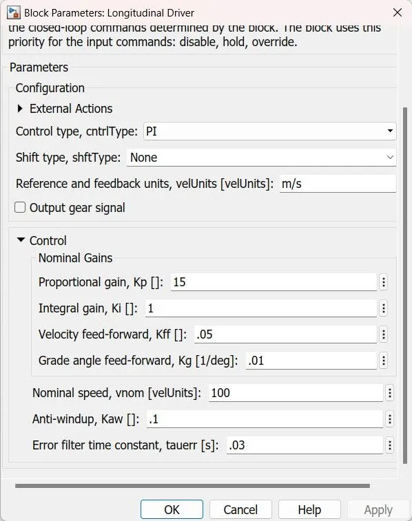
so , the longitudinal driver is another block which is actually the part of Powertrain Blockset will work on the PI controller type and if you see the control block here wee will see the proportional Gain into integral Gain , feed velocity forward, feed grade angle, Normal speed units and Anti-windup as well. so, thesee are the PI controller parameters and the driver will work in such a way that it will generate the Acceleration command and Break command.
Multiport Switch:
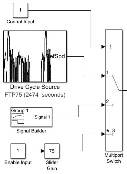
The Multiport Switch block determines which of several inputs to the block passes to the output. The block bases this decision on the value of the first input. The first input is the control input and the remaining inputs are the data inputs. The value of the control input determines which data input passes to the output.
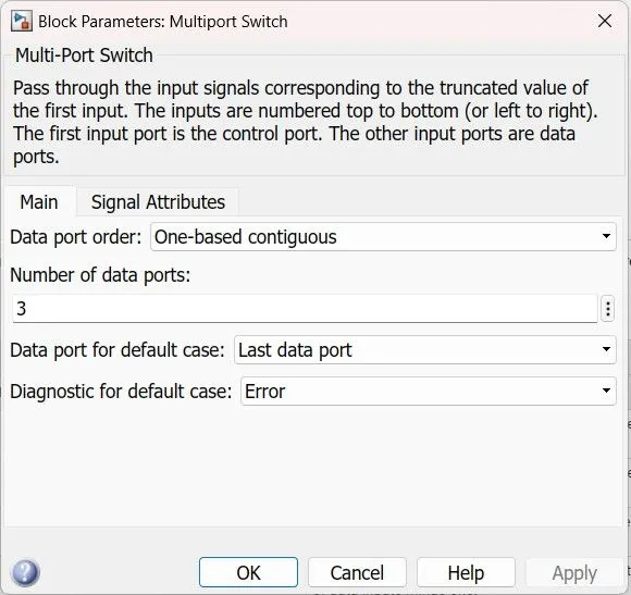
Double click on the Multiport switch we can assign the Number of input port.
Drive Cycle
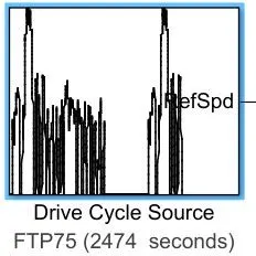
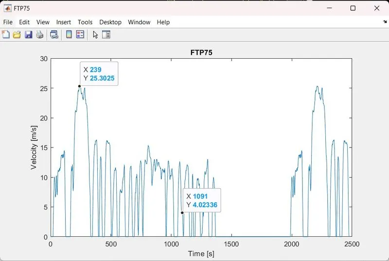
Here, how the model run exactly we want to give as controlled signals, we can actually decide speed to running a simulation and that is possible by using a drive cycle resource so the drive cycle resource is nothing but the block which can take the drive cycle data and this is nothing but a speed versus time Graph. So here you can see the Drive cycle source, there is number of Drive cycles which automakers are going to follow for their Emission testing for their mileage testing.
we are going to use FTP75 (2474 seconds) .
Select the drive cycle alone so this is the Velocity (meter/ second) on Y- axis and the time in seconds on the X-axis.
So look at how the velocity varies and look at the highest speed of the Vehicle value of which is 25 meter/ second.
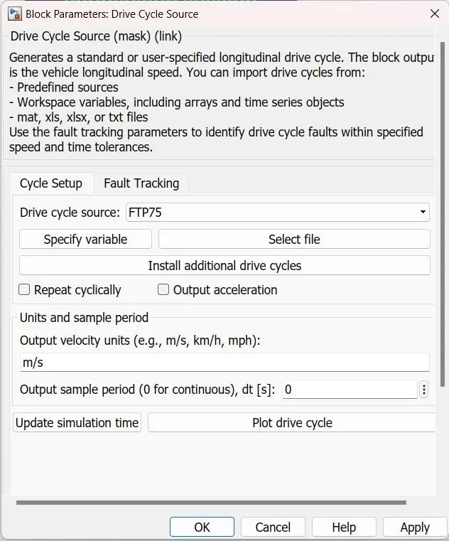
If we Double click on the Drive cycle Block we have one window where we can apply the parameters, here we can select the Drive cycle source input , we can specity the variable it takes Variable created in the MATLAB from the workspace. we can select the file from the drive which is in the form of .mat, .xlsx and .txt file extension name.
we can assign the output velocity units it may be m/s, km/s, mph. and we can plot drive cycle which we are selected. we are going to use this Drive cycle as a define input to the vehicle if we can plot the drive cycle before actually running simulation
Signal Builder:
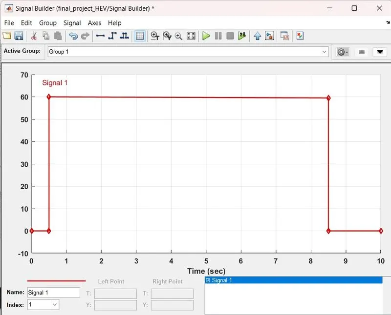
In the Signal Builder window, create signals and define the output waveforms. The Signal Builder block allows you to create interchangeable groups of piecewise linear signal sources and use them in a model.
Slider Gain:

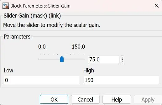
The Slider Gain block performs a scalar gain that you can modify during simulation. Modify the gain using the slider parameter.
Solver Configuration:
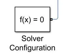
Simscape block diagram requires exactly one Solver Configuration block to be connected to your Model. Each physical network represented by a connected Simscape block diagram requires solver settings information for simulation.
Explaination of the Model of Electric Vehicle:
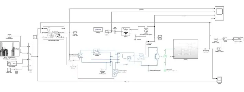
Simulate the model for FTP75 (2474) seconds and find the final car Distance in Km in the scope.
This Model consist of three parts
- Logical Part
- Electrical Part
- Mechnicial Part
Left side if we see there are various Drive cycles are their like Powertrain Drive cycle source, Signal Builder, Slider Gain, From Workspace these are the Drive cycles.so we can select only one Drive cycle at one time from the Multiport switch, has number of data input and one control input. with this control input we can allow only one Drive cycle source.
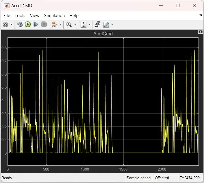
The output of the Multiport switch is giving to Driver which is Longitudinal Driver. The Longitudinal Driver block compare the Actual reference speed with Vehicle speed of the Vehicle body. It has two output command that is Acceleration Command and Deceleration command. when the Acceleration command is received from Controlled Voltage Source AccelCmd Block, by the physical input signal port. It gives input to Controlled PWM Voltage block so it generates the pulse when the duty cycle is 0% it generates 0 and when the duty cycle is 100% it generates 1. which is pulse width modulation.
This block represents an H-bridge motor drive. The block can be driven by the Controlled PWM Voltage block in PWM or Averaged mode. In PWM mode, the motor is powered if the PWM port voltage is above the Enable threshold voltage. Assumptions about the load, the block applies an average voltage to the load that achieves the correct average load current. The Simulation mode parameter value must be the same for the Controlled PWM Voltage and H-Bridge blocks.
The rotor shaft of the Motor is rotates the mechanical rotational conserving ports Connections B (base). base and follower rotation directions with the Output shaft rotates the Rear Axle of the Vehicle then the Vehicle Moving according to Acceleration Command and Stop moving if apllied Breaks.
The output comming from the Vehicle is physical signal is converted into simulink and the integrate the speed it gives Distance traveled by the Vehicle in km/hr and the divide by 3600 and finally we have the Distance in KM only.
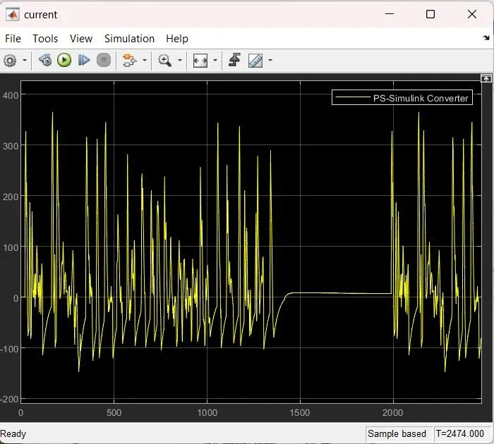
The current sensor sense the current Drawing by DC motor which is physical output port of the current sensor and observe by the scope.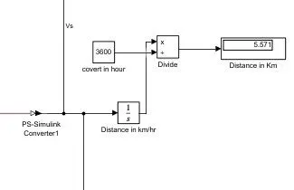
State of charge of the Battery can be observe from the scope SOC%.
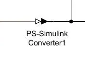 It Converts the Physical Signal to a Simulink input signal.
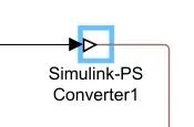
it Converts the Simulink input signal to a Physical Signal.

above Blue one is the Electric Reference for electrical circuit and Green one is the Mechanical Reference for Mechical model, if this is not connected the we wll get error.
Result of Acceleration Command
Result of Battery Current:
Result of State of Charge (SOC %)
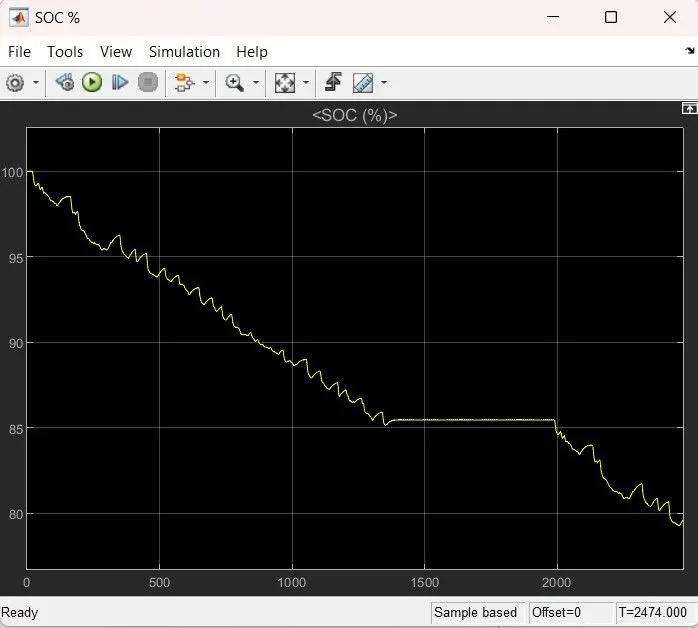
the above scope shows from 0 to 2474 seconds the Battery comsume by the Vehicle is around 20% from the full charge of 100%.
Result of Drive Cycle vs Vehicle speed
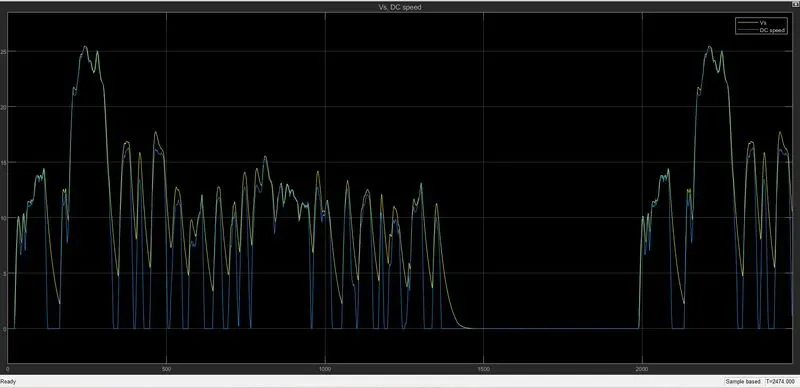
From above scope result we can find our Vechile speed is follows the Drive cycle source input Both Drive cycle and Vehicle speed have the Highest velocity is 25.53 meter per seconds.
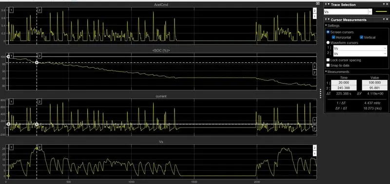
In the above scope we can consider that highest velocity of the speed Vehicle is 25.53 m/s at 245.388 seconds.
this scope we have find from initial codition to the duration of 20 Second the Vehicle is in idle condition or stand still condition that is vehicleis not moving.
Upto duration of 20 seconds Acceleration Command, State of Charge, Current getting by DC motor, and Vehicle speed all are initial condition.
Duration (1358 to 1989) seconds the SOC fall down (85.41 to 84.92) means 0.49%. at this duration the Vehicle is not moving but Auxillary Acessories are taking the Battery power.
Conclusion:
- We created a Electric Vehicle Model by using Simulink Library Block which uses a battery and a DC motor.
- The Distance Travelled by Electric Vehicle using FTP75,Drive cycle is 5.57 km in 2474 seconds.
- The State of charge (SOC) of the battery was Discharged upto 20% from full charge, remaning SOC of the Battery 80%