Final Project: Design of an Electric Vehicle
Create a MATLAB model of electric car which uses a battery and a DC motor. Choose suitable blocks from Powertrain block set. Prepare a report about your model including following:
Objectives:
1. System level configurations
2. Model parameters
3. Results
4. Conclusion
Solution :-
lectric vehicle (EV) is defined as a vehicle that uses an electric motor or a traction motor for propulsion unlikely to an internal combustion (IC) engine used by conventional vehicles. Electric vehicles use electric power instead of fuels as conventional vehicles would and because of this difference, electric vehicles do not produce any exhaust gases or pollution(Zero emission). The power needed for the operation of an EV can come from a variety of sources such as batteries, generators, or through a collector system.
MATLAB model of electric car which uses lithium ion battery and induction motor. Choose suitable blocks from Powertrain block set :
To Model and Simulate an electric vehicle with SIMULINK.
Let us consider a model in this report, an electric vehicle with a Induction motor and battery system using the SIMULINK . In modelling this EV for a drive cycle and to check performance parameters : to measure speed, SOC , and the current characteristics of its battery system etc
Components :-
The main components of modelling an EV are:
- Vehicle body
- Motor & motor controllers
- Power converters
- Batteries
- Drive cycle
BLOCK DIAGRAM:
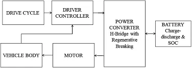
The most important components of electric vehicle areas:
- Auxiliary Battery: In an electric drive vehicle, the auxiliary battery provides electricity to power vehicle accessories.
- Traction Battery Pack: Traction battery pack is also known as Electric Vehicle Battery (EVB) which is used to store the electricity. Some examples of traction battery energy storage systems are as given:
- Lithium-Ion
- Nickel-Metal Hydride
- Lead-Acid
- Ultra-Capacitors
- DC/DC Converter: Basically, DC/DC converter is an electronic device which is used to converts higher-voltage DC power from the traction battery pack to the lower-voltage DC power. The converted power is used to run the vehicle accessories. It is also used to recharge the auxiliary battery.
- Electric Traction Motor: Another important component is electric traction motor and this device is used to provide motive power to the wheels.
- Onboard charger: Takes the incoming AC electricity supplied via the charge port and converts it to DC power for charging the traction battery. It monitors battery characteristics such as voltage, current, temperature, and state of charge while charging the pack.
- Power electronics controller: This unit manages the flow of electrical energy delivered by the traction battery, controlling the speed of the electric traction motor and the torque it produces.
- Charge port: The charge port allows the vehicle to connect to an external power supply in order to charge the traction battery pack.
- Thermal system (cooling): This system maintains a proper operating temperature range of the electric motor, power electronics, and other components.
Vehicle body -
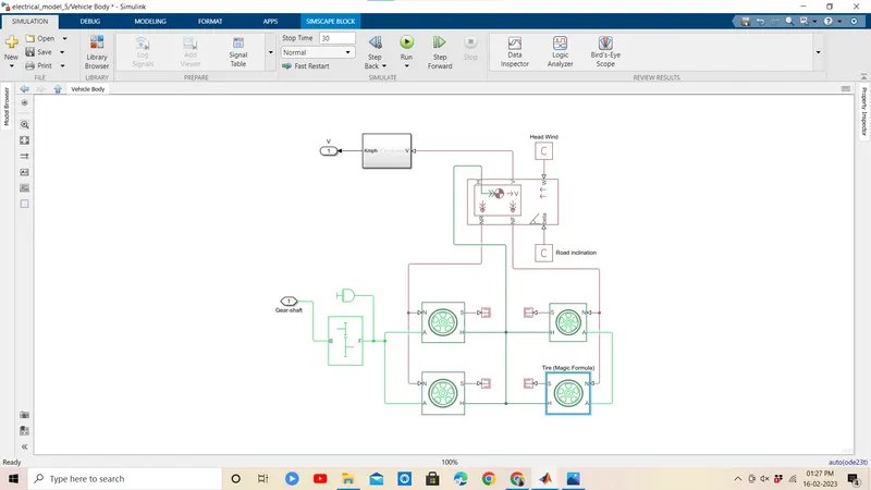
- The vehicle is assumed to be a front axle driven (4 wheels - 2 on each axle).
- The wheels are modelled using simple Tire (Magic formula) simulink blocks.
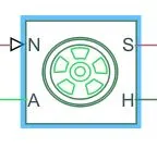
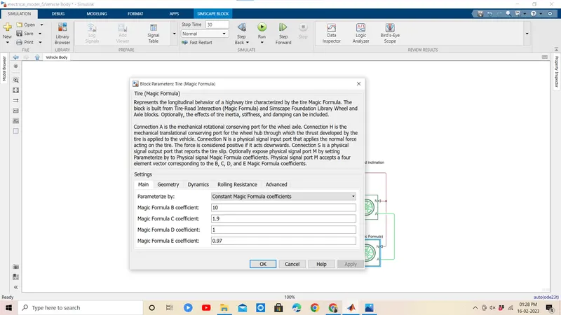
- The N port of the tire corresponds to the Normal Reaction acting on it.
The A port corresponds to the Mechanical Rotational conserving port for the wheel axle. Thus both the wheels on the same axle should form a connection through their respective A ports.
Connection H corresponds to the Mechanical Translational conserving port for the wheel hub through which the thrust developed by the tire is applied to the vehicle. Thus, all the 4 wheels form a connection through their respective H ports and this is in turn connected to the translational hub of the vehicle body.
The connection S represents the output port for slip of the tire.
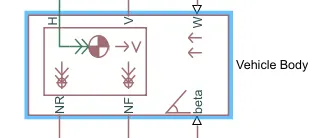
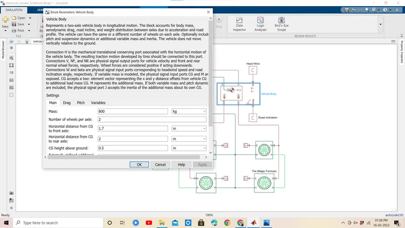
Represents a two-axle vehicle body in longitudinal motion. The block accounts for body mass, aerodynamic drag, road incline, and weight distribution between axles due to acceleration and road profile. The vehicle can have the same or a different number of wheels on each axle. Optionally include pitch and suspension dynamics or additional variable mass and inertia. The vehicle does not move vertically relative to the ground.
Connection H is the mechanical translational conserving port associated with the horizontal motion of the vehicle body. The resulting traction motion developed by tires should be connected to this port. Connections V, NF, and NR are physical signal output ports for vehicle velocity and front and rear normal wheel forces, respectively. Wheel forces are considered positive if acting downwards. Connections W and beta are physical signal input ports corresponding to headwind speed and road inclination angle, respectively. If variable mass is modeled, the physical signal input ports CG and M are exposed. CG accepts a two- element vector representing the x and y distance offsets from vehicle CG to additional load mass CG. M represents the additional mass. If both variable mass and pitch dynamics are included, the physical signal port J accepts the inertia of the additional mass about its own CG.
(1) Vehicle Body Subsystem
- Motor & motor controllers--
- Simulink provides an inbuilt bodel block for DC motor which converts electrical input into mechanical rotational output.
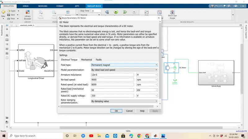
Note : Here, the blue colour corresponds to the electrical side of the motor and the green colour corresponds to the mechanical side. - Here, the motor field type is kept as Permanent magnet and the model parameterization is done by rated load and speed.
The armature inductance and the mechanical parameters are given their default values.
All the other parameters are changed as shown below -
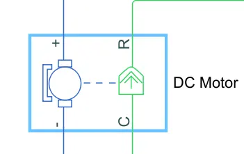
This is the DC Motor which would give the rotational power to the wheels and become the sole power generation source.
The DC Motors terminals are connected as mentioned below,
+ = Electrical signal to the motor Positive Terminal
- = Electrical signal to the motor Negative Terminal
R = Casing of the Motor connected with the Mechanical Rotational Reference Block
C = Rotor Case connected to the Mechanical Rotational reference
The parameter considered are, The Armature inductance is as default, varied the changes in the No-Load Speed @ 8000 rpm, the rated speed @ 5000 rpm, the Rated Load at 50kW, and the Rated DC Supply Voltage @ 300 V. All other parameters are as default.
- Power converters
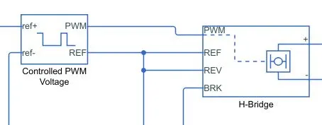
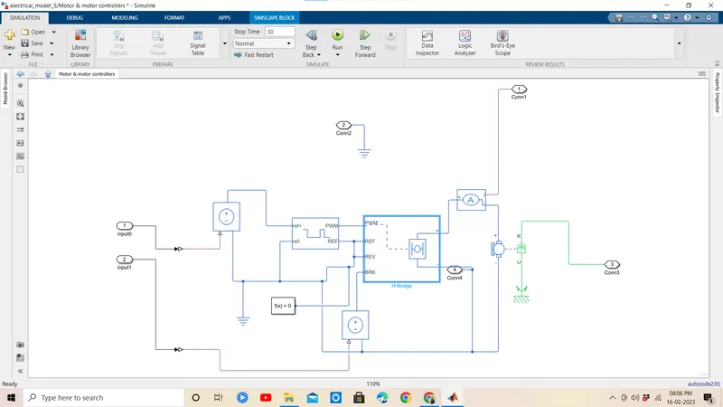
The H-Bridge helps in controlling the power that is input according to the requirement. The output provided are converted voltage as per the controlled parameters.
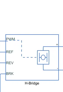
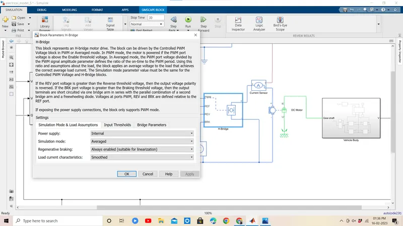
- his block represents an H-bridge motor drive. The block can be driven by the Controlled PWM Voltage block in PWM or Averaged mode.
- In PWM mode, the motor is powered if the PWM port voltage is above the enabled threshold voltage.
- In Averaged mode, the PWM port voltage divided by the PWM signal amplitude parameter defines the ratio of the on-time to the PWM period.
- Connection REF is for the reference input. This combined with the PWM connected will form the pulse input for the H-Bridge.
Here, the REF input is connected to the Electrical Reference (ground). - Connection REV corresponds to the reverse motion of the motor which essentially means, the backward motion of the vehicle.
Here, the backward motion of the vehicle is not accounted for and so, the port is connected to the electrical reference. - Connection BRK is for the braking of the vehicle.
- Since, the PWM mode results in a huge amount of simulation time, Averaged mode is selected for this simulation.
- Load current characteristics are considered to be smoothed here.
- Also, the regenerative braking is anabled for the simulation. This means, when the vehicle starts decelerating, corresponding amount of charge will be fed back to the battery.
Accordingly, the BRK input is connected to a Controlled Voltage Source. This will generate emf corresponding to the intensity of brakes applied and fed the power back to the battery.
Controlled PWM Voltage -
he Controlled PWM Voltage Block helps in keeping the Modulated Pulses as per the required pulses. So that the operations happens smooth and higher variations are not observed.
The Ports are connected as follows,
ref+ = Reference Positive connected with the Acceleration Commands from the Driver Model
ref- = Reference Negative connected with the Deceleration Commands from the Driver Model
PWM = PWM connected directly to the H-Block
REF = REF connected directly to the H-Block
Note :The parameters are set as default.
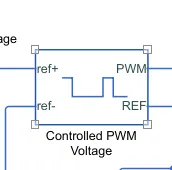
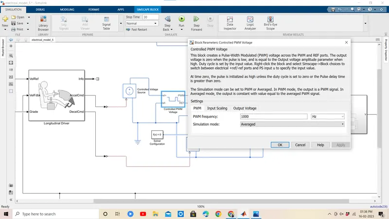
Simulink provides an inbuilt Controlled PWM Voltage block. This block is used for providing the proper pulse inputs to the H-Brdige circuit.
- The PWM & REF connections are for the corresponding ports on the H-Bridge circuit.
The 2 reference inputs correspond to the throttle inputs given by the driver. The block generates corresponding pulse width as per the accelerations and brakes apllied by the driver himself. - Here, the PWM frequency is 1000 Hz. Also, the simulation mode is Averaged as that in the H-Bridge circuit.
- The input scaling parameters given are -
0V for 0% duty cycle and 5V for 100% duty cycle. Accordingly, the output voltage amplitude becomes 5V. - The H-Bridge circuit along with the PWM input, together form the motor controller circuit.
- Batteries--
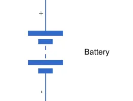
- To model the Battery pak, a simple Battery block is used. This is because, if the generic battery block is used instead, the simulation will run for a much longer time.
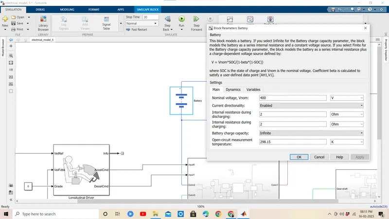
- Here, the selected option for Battery Charge Capacity is Finite. Accordingly, the block models the battery as a series internal resistance plus a charge-dependent voltage source.
If the chosen option had been Infinite, the voltage source would have been constant. - Also, the self-discharging of the battery and the battery dynaics are disabled.
- The Battery Nominal Voltage is given as 400V.
The Ampere-hour rating is assumed to be 50.
The rest all paramaters are left with their default values.
Battery State of Charge :
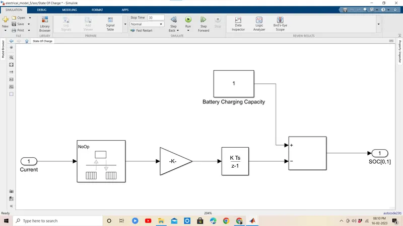
- A small subsystem is created to calculate the State of Charge of the battery.
- This subsystem takes the battery current as the input.
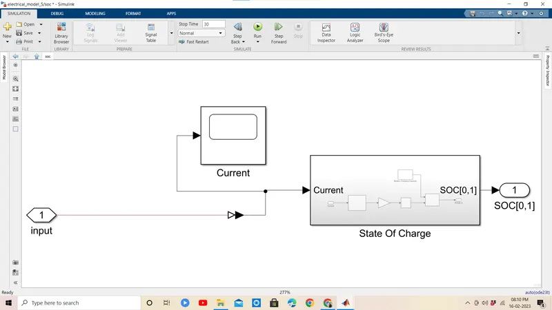
- The essential process to calculate the SOC is by subtracting the charge from the rated capacity of the battery.
- Accordingly, the current is integrated w.r.t. time to get the charge in coulumbs. Now this coulumb value is modified into Ampere hours.
This value is now subtracted from the charging capacity of the battery i.e. 50 Ah. - Finally, the remaining charge is now converted into percentage value of the charging capacity of the battery.
- Drive cycle
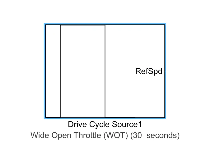
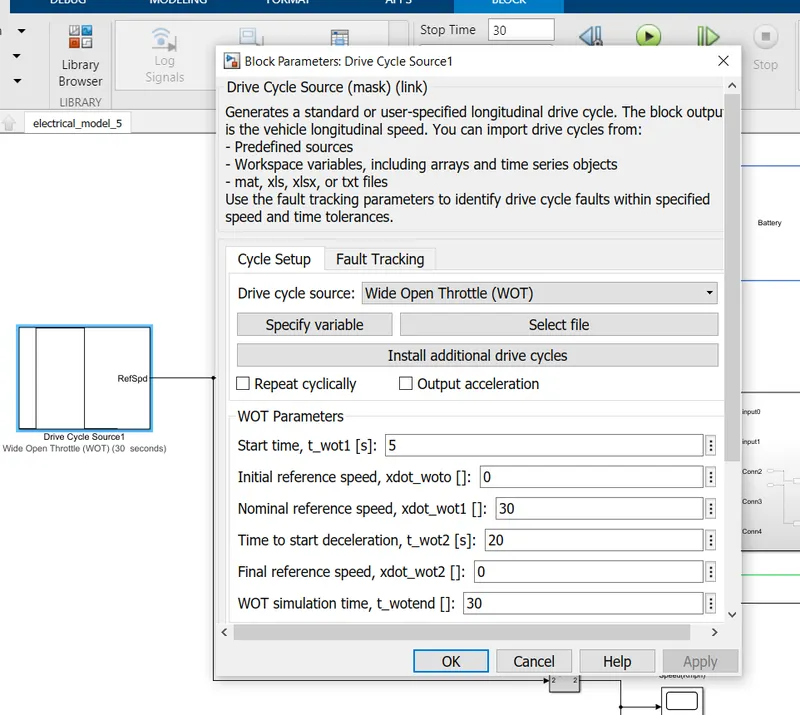
wind open throttle-drive cycle used
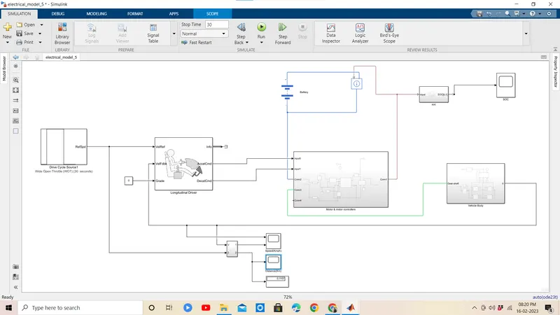
The Driver Model has the Input and Output Ports which are connected to the following,
Velocity Reference - Drive Cycle
Velocity Feedback - Distance Calculation
Grade - Constant 0
Info - Not Connected
Acceleration Command - Controlled PWM Source
Deceleration Command - Brake in H-Bridge to maintain the speed according to the Drive Cycle.
Simulation --
Outputs --
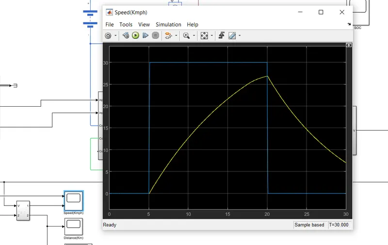
(1) Ref. Speed v/s Actual vehicle speed :
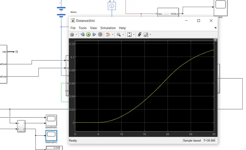
Distance Covered :
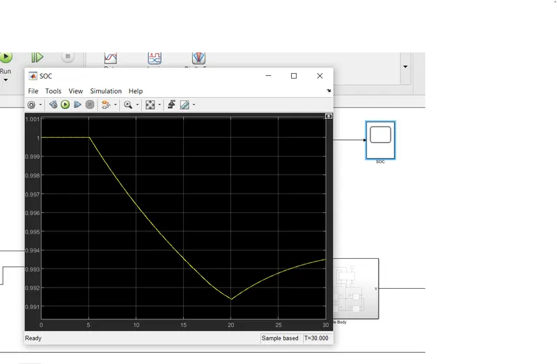
2. Battery SOC :
CONCLUSION
The model was succesfully ran for simulation under the standard wind open throttle drive cycle. The results have been properly analyzed.
Also, learnt quite a lot of interesting things like -
- how to model an EV and carry out a real time simulation
- how a motor controller works and what role it plays in the control of the electric motor
- how to calculate the SOC of the battery
- different powertrain blocks provided by simulink which can be used to simulate a vehicle model.