Final Project: Design of an Electric Vehicle
DESIGN OF AN ELECTRIC VEHICLE:
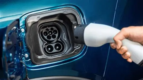
Here i have taken an Electric Vehicle
TATA NEXON EV
BLOCKS NEED TO BE SIMULATE THE MODEL:
- Drive cycle source
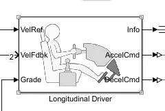
- Longitudinal Driver
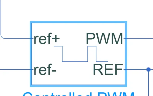
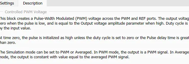
- Controlled PWM voltage
- H-bridge
- DC motor
- Vehicle body
- Tire (Magic Formula)
- Simple gear
- Electrical Reference
- Mechanical Reference
- Inertia
- PS constant
- Battery
- Controlled voltage source
- Controlled current source
- Terminator
- Solver configuration
- Integrator
- scope
- Display
- Sum
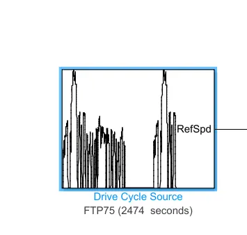
Drive cycle
we can use multiple drive cycle by just adding the multiple switch block after the drive cycles
A driving cycle is a series of data points representing the speed of a vehicle versus time.
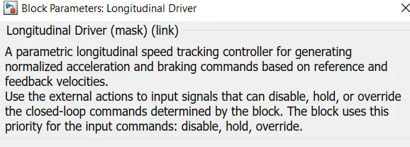
Longitudinal driver
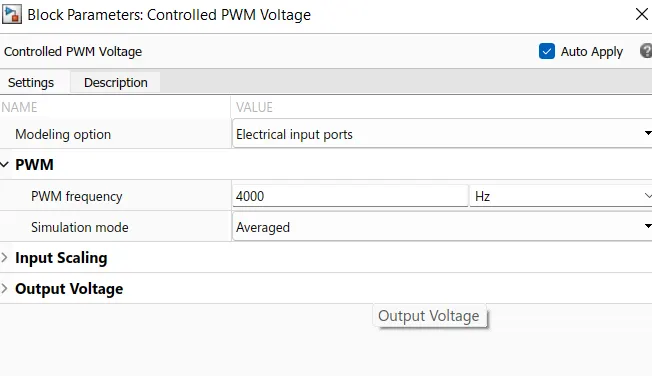
Controlled PWM voltage
H-bridge
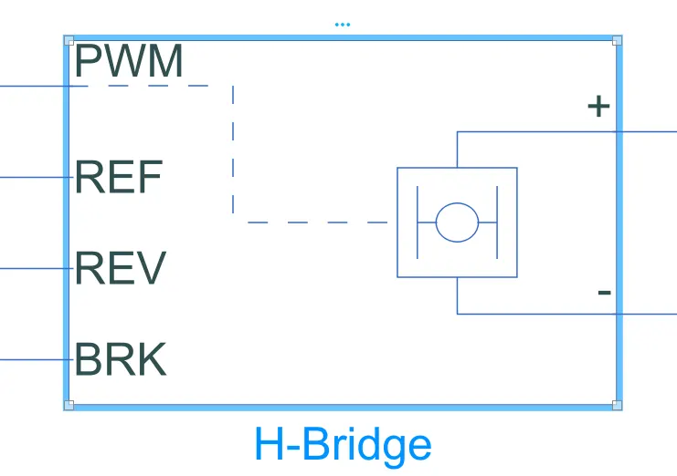
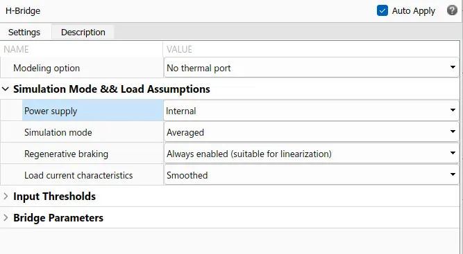
This block represents an H-bridge motor drive. The block can be driven by the Controlled PWM Voltage block in PWM or Averaged mode. In PWM mode, the motor is powered if the PWM port voltage is above the Enable threshold voltage.
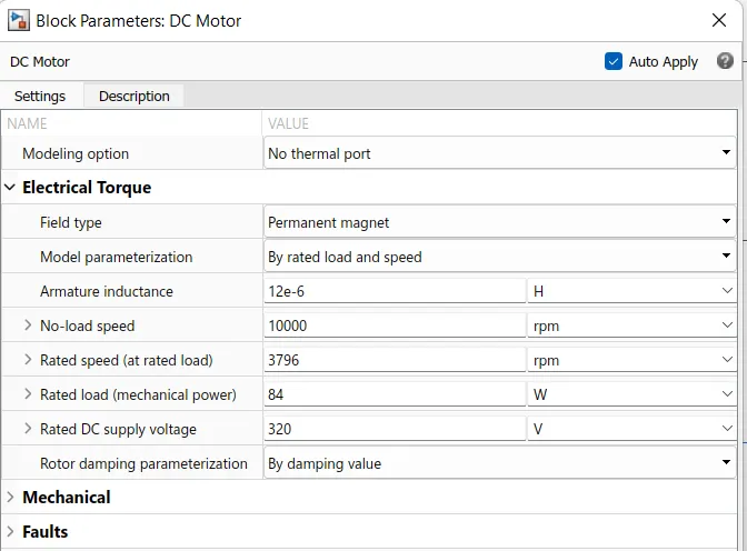
DC motor
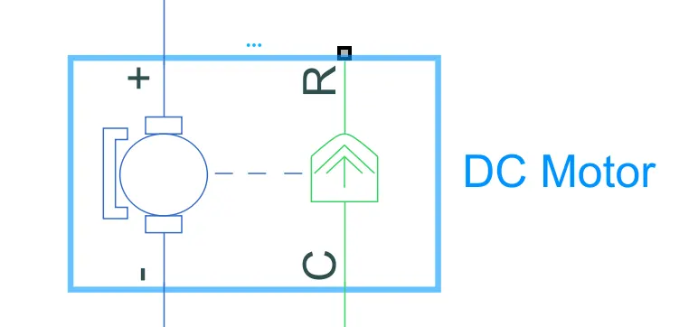
This block represents the electrical and torque characteristics of a DC motor.
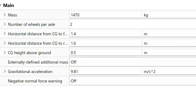
Vehicle body
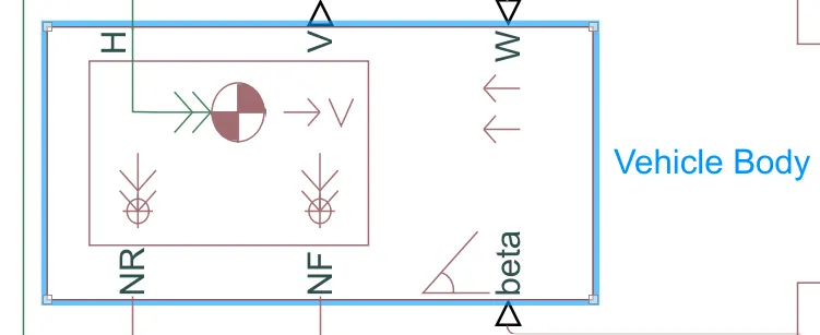
this block represents the vehicle body which includes the wheels and vehicle weight etc.
NR- represents the rear wheel connection
NF- represents the front wheel connection
V- represents the vehicle speed
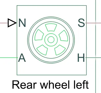
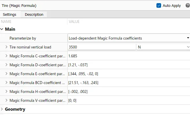
Tire (magic formula)
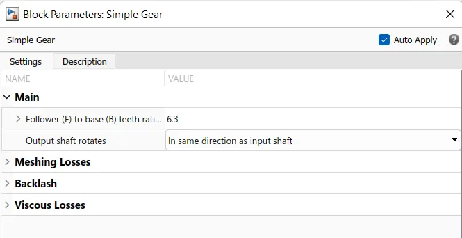
Simple Gear
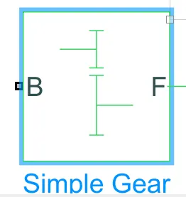
Represents a fixed-ratio gear or gear box. No inertia or compliance is modeled in this block. You can optionally include gear meshing, backlash, and viscous bearing losses.
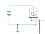
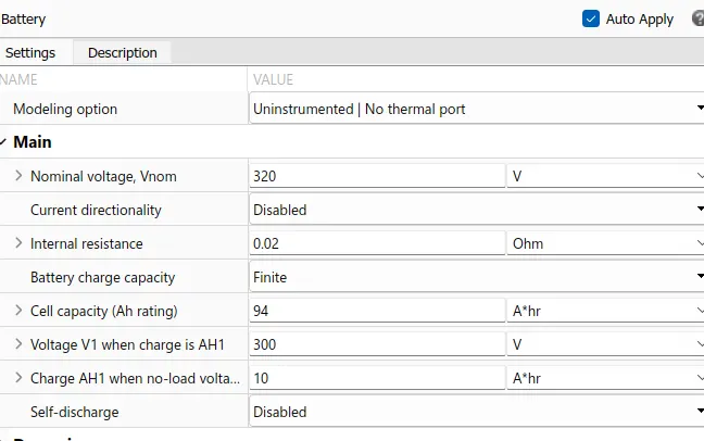
Battery
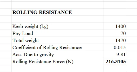
Rolling resistance Force:
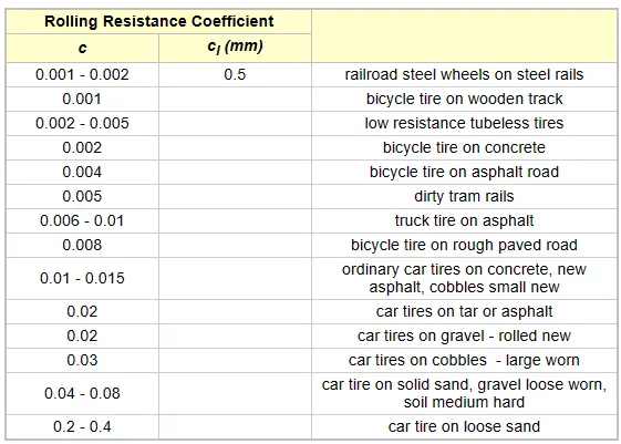
Rolling Ressitance coefficient according to the type of the vehicle..
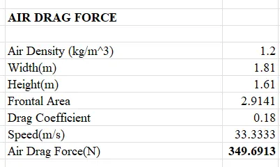
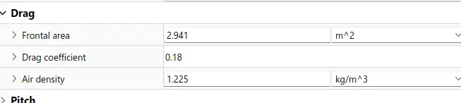
Air drag force:
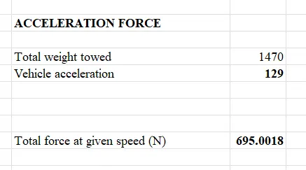
Total force:
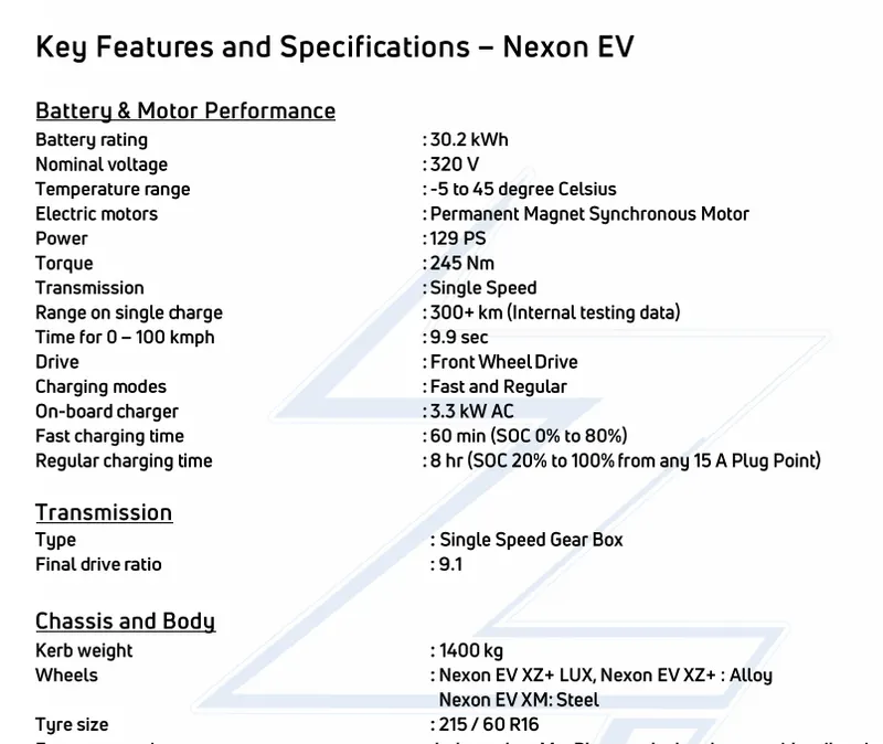
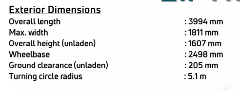
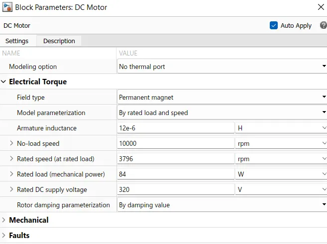
Motor parameters & specifications:
Here the final model of the EV
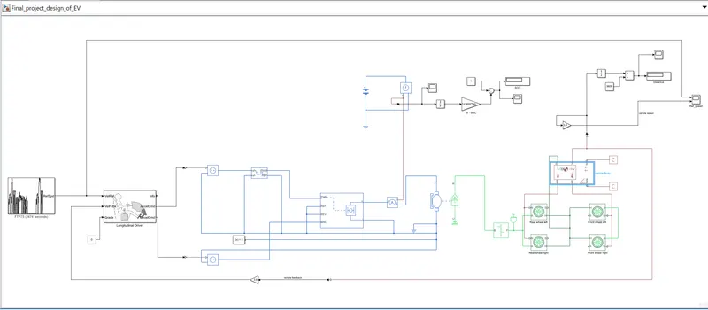
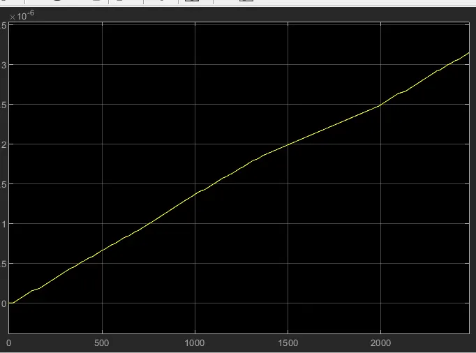
By using FTP75 drive cycle for 2474 seconds the vehicle travels the distance of 3.145km
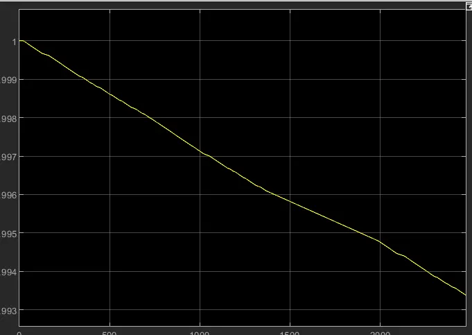
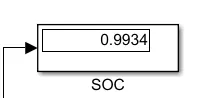
State of charge SOC
State of charge SOC
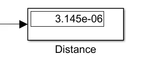
distance