Final Project: Design of an Electric Vehicle
OBJECTIVES :
To prepare a technical report about the EV model including
- System level configurations
- Model parameters
- Results
- Conclusion
THEORY :
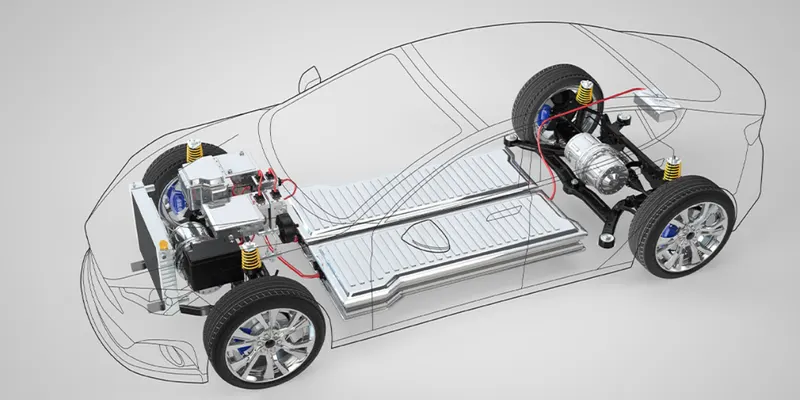
Fig A : Electric vehicle
An electric vehicle (EV) is a vehicle that uses one or more electric motor for propulsion . It can be powered by a collector system, with electricity from extravehicular sources, or it can be powered autonomously by a battery (sometimes charged by solar panels or by converting fuel to electricity using fuel cells or a generator) EVs include, but are not limited to, road and rail vehicles surface and underwater vessels electric air craft and electric spacecraft . For road vehicles, together with other emerging automotive technologies such as autonomous driving, connected vehicles and shared mobility, EVs form a future mobility vision called Connected, Autonomous, Shared and Electric (CASE) Mobility.
EVs first came into existence in the late 19th century, when electricity was among the preferred methods for motor vehicle propulsion, providing a level of comfort and ease of operation that could not be achieved by the gasoline cars of the time. Internal combustion engine were the dominant propulsion method for cars and trucks for about 100 years, but electric power remained commonplace in other vehicle types, such as trains and smaller vehicles of all types.
In the 21st century, EVs have seen a resurgence due to technological developments, and an increased focus on renewable energy and the potential reduction of transportation impact on air pollution project drawdown describes electric vehicles as one of the 100 best contemporary solutions for addressing climate change.
Components of an EV
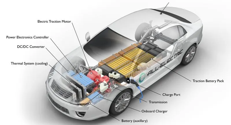
Fig B : Components of Electric vehicle
EV’s are like an automatic car. They have a forward and reverse mode. When you place the vehicle in gear and press on the accelerator pedal these things happen:
Power is converted from the DC battery to AC for the electric motor
- The accelerator pedal sends a signal to the controller which adjusts the vehicle's speed by changing the frequency of the AC power from the inverter to the motor
- The motor connects and turns the wheels.
When the brakes are pressed or the car is decelerating, the motor becomes an alternator and produces power, which is sent back to the battery.
AC/DC and electric cars
AC stands for Alternating Current. In AC, the current changes direction at a determined frequency, like the pendulum on a clock.
DC stands for Direct Current. In DC, the current flows in one direction only, from positive to negative.
Block diagram of an EV
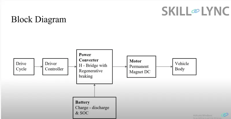
Fig C : Block diagram of an EV
Battery Electric Vehicles
The key components of a Battery Electric Vehicle are:
- Electric motor
- Inverter
- Battery
- Battery charger
- Controller
- On board charger
- DC-DC converter
- Charging port
- Transmission
Thermal system (Cooling)
Electric motor
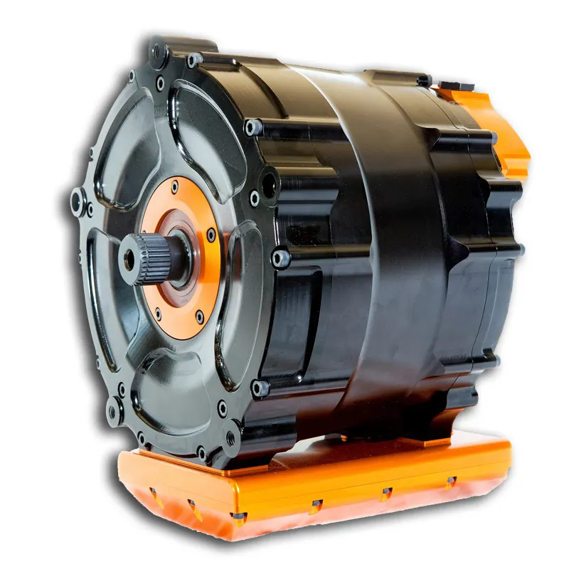
Fig D : Electric motor / Traction motor .
Electric traction motor:
Electric traction motor is the main components of electric vehicle. The motor converts the electrical energy into kinetic energy. This energy rotates the wheels. Electric motor is the main component that differentiates an electric car from conventional cars. An important feature of an electric motor is the regenerative braking mechanism . This mechanism slows down the vehicle by converting its kinetic energy into another form, and storing it for future use. There are basically two types of motors DC and AC motors.Using power from the traction battery pack, this motor drives the vehicle's wheels. Some vehicles use motor generators that perform both the drive and regeneration functions.
electric motors in everything from juicers and toothbrushes, washing machines and dryers, to robots. They are familiar, reliable and very durable. Electric vehicle motors use AC power.
Inverter
An inverter is a device that converts DC power to the AC power used in an electric vehicle motor. The inverter can change the speed at which the motor rotates by adjusting the frequency of the alternating current. It can also increase or decrease the power or torque of the motor by adjusting the amplitude of the signal.It coverts DC power from the batteries to AC power. It also converts the AC current generated during regenerative braking into DC current. This is further used to recharge the batteries. The inverter can change the speed of the motor.
Battery
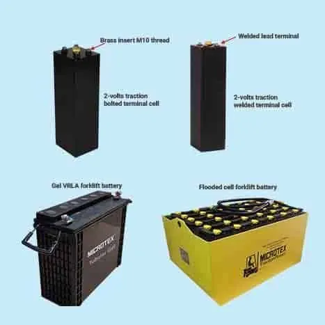
Fig E : Traction battery pack
Traction battery pack is also known as electric vehicle battery . It powers the electric motors of an electric vehicle. The battery acts as an electrical storage system. It stores energy in the form DC current. The range will be higher with increasing kW of the battery. The life and operation of the battery depends on its design. The lifetime of a traction battery pack is estimated to be 200,000 miles.The charge port allows the vehicle to connect to an external power supply in order to charge the traction battery pack. An electric vehicle uses a battery to store electrical energy that is ready to use. A battery pack is made up of a number of cells that are grouped into modules. Once the battery has sufficient energy stored, the vehicle is ready to use. Battery (all-electric auxiliary): In an electric drive vehicle, the auxiliary battery provides electricity to power vehicle accessories.
Battery technology has improved hugely in recent years. Current EV batteries are lithium based. These have a very low rate of discharge. This means an EV should not lose charge if it isn't driven for a few days, or even weeks.
Battery charger
The battery charger converts the AC power available on our electricity network to DC power stored in a battery. It controls the voltage level of the battery cells by adjusting the rate of charge. It will also monitor the cell temperatures and control the charge to help keep the battery healthy.
Controller
Power electronics controller:
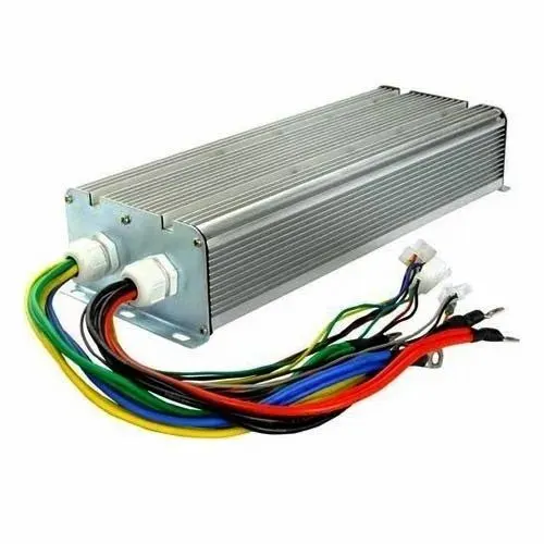
Fig F : Power electronics controller
Power electronics controller determines the working of an electric car. It performs the regulation of electrical energy from the batteries to the electric motors. The pedal set by the driver determines the speed of the car and frequency of variation of voltage that is input to the motor. It also controls the torque produced.This unit manages the flow of electrical energy delivered by the traction battery, controlling the speed of the electric traction motor and the torque it produces.
The controller is like the brain of a vehicle, managing all of its parameters. It controls the rate of charge using information from the battery. It also translates pressure on the accelerator pedal to adjust speed in the motor inverter.
Onboard charger:
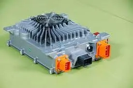
Fig G : On board charger
Takes the incoming AC electricity supplied via the charge port and converts it to DC power for charging the traction battery. It also communicates with the charging equipment and monitors battery characteristics such as voltage, current, temperature, and state of charge while charging the pack. Onboard charger is used to convert the AC supply received from the charge port to DC supply. The on board charger is located and installed inside the car. It monitors various battery characteristics and controls the current flowing inside the battery pack.
A charging cable for standard charging is supplied with and stored in the vehicle. It's used for charging at home or at standard public charge points. A fast charge point will have its own cable.
DC-DC converter :
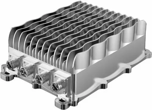
Fig H : DC-DC converter
This device converts higher-voltage DC power from the traction battery pack to the lower-voltage DC power needed to run vehicle accessories and recharge the auxiliary battery.
The traction battery pack delivers a constant voltage. But different components of the vehicle has different requirements. The DC-DC converter distributes the output power that is coming from the battery to a required level. It also provides the voltage required to charge the auxiliary battery.
Charge Port
Fig I : Charge port
The charge port connects the electric vehicle to an external supply. It charges the battery pack. The charge port is sometimes located in the front or rear part of the vehicle
Transmission
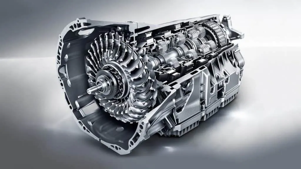
Fig J : Trsnsmission system in EV
It is used to transfer the mechanical power from the electric motor to the wheels, through a gearbox . The advantage of electric cars is that they do not require multi-speed transmissions. The transmission efficiency should be high to avoid power loss.The transmission transfers mechanical power from the electric traction motor to drive the wheels.
Thermal system (cooling):
This system maintains a proper operating temperature range of the engine, electric motor, power electronics, and other components.
EV versus ICE
The most significant difference between ICE (Internal Combustion Engine), BEVs and PHEVs is found in the powertrain, the components that generate motive (moving) power and deliver it to the wheels to move the car.
- ICE vehicles burn fuel (usually petrol or diesel) that releases heat to move parts of the engine and other components that deliver power to the wheels. The ignition starts this combustion process.
- BEVs use power stored as electricity in rechargeable batteries and deliver it via one or more electric motors to the wheels.box
- PHEVs have both ICE and electric components, along with controls that manage the balance of electric and ICE power used while driving.
How it works
Through the ignition and combustion of a 15:1 air-fuel mix, the ICE engine converts thermal energy into mechanical energy and emits waste exhaust gases in the process. Improvements in efficiency and evolving emission standards, ICE technology has not changed much in the last 100 years.
There are hundreds of moving parts with tight tolerances that must work together to keep the combustion engine running. When the combustion process starts you can hear and feel the vibrations in the vehicle caused by the mechanical and hydraulic systems.
ICE engines produce power in a limited speed range and use gears to maintain acceleration. Fuel keeps burning as long as the engine is switched on, even when the car is idling.
Electrical powertrains convert electrical energy (stored in the battery), into mechanical energy which turns the motor, rotating the wheels. EVs have 90% fewer moving parts than ICE vehicles.
The electric vehicle reference application represents a full electric vehicle model with a motor-generator, battery, direct-drive transmission, and associated powertrain control algorithms. Use the electric vehicle reference application for powertrain matching analysis and component selection, control and diagnostic algorithm design, and hardware-in-the-loop (HIL) testing. To create and open a working copy of the conventional vehicle reference application project, enter
The electric vehicle reference application is configured with a mapped motor and battery. This diagram shows the powertrain configuration.
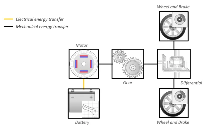
Fig K: Powertain with differential whee with brake and axle,gear, motor and battery
1. Vehicle Body Subsystem :
- The vehicle is assumed to be a front axle driven (4 wheels - 2 on each axle).
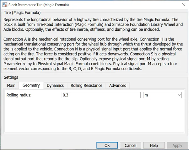
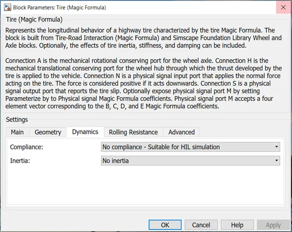
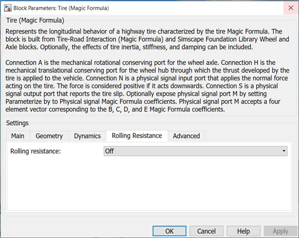
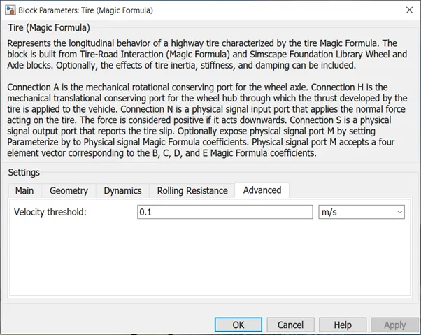
- The wheels are modelled using simple Tire (Magic formula) simulink blocks.
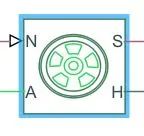
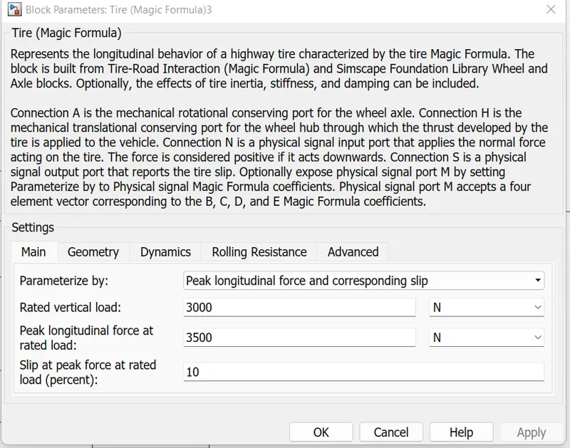
- The tires are parameterized by Peak longitudinal force and corresponding slip.
- The other block parameters such as - rated vertical load, peak longitudinal force at rated load and slip at peak force at rated load - are kept with their default values.
- The tire radius is given as 0.3 m.
- The tire inertia is kept as 1 kg-m^2. Also, the rolling resistance is given with a constant coefficient of 0.015.
- Vehicle body mass, Centre of gravity distance values and aerodynamic drag variables are modified.
- Pitch dynamics are kept ON with other variable values as default values.The N port of the tire corresponds to the Normal Reaction acting on it.
The A port corresponds to the Mechanical Rotational conserving port for the wheel axle. Thus both the wheels on the same axle should form a connection through their respective A ports. - Connection H corresponds to the Mechanical Translational conserving port for the wheel hub through which the thrust developed by the tire is applied to the vehicle.
- Thus, all the 4 wheels form a connection through their respective H ports and this is in turn connected to the translational hub of the vehicle body.
- The connection S represents the output port for slip of the tire.
- The magic tire block models a tire with longitudinal behaviour which is given by a magic formula an empirical equation based on four fitting coefficients.
- Under constant or variable pavement conditions this block can model tire dynamics.
- The longitudinal direction of the tire is same as the direction of motion as it rolls on the pavement.
Input Port:
- N - Normal force acting on tire, positive when force is acting downwards/towards the contact surface,
Output Port:
- S - Slip value relative to tire and surface of contact.
Conserving Ports:used to model a tire with longitudinal behavior given by equation based on four fitting coefficients.
The block can model tire dynamics under constant or variable contact surface conditions. - Connection A is referred to the mechanical rotational conserving port for the wheel axle. Connection H is the mechanical translational conserving port for the wheel hub through which the thrust is developed by the tire which is applied to the wheel.
- Connection N is a physical signal input port that applies the normal force acting on the tire. If it is acting downwards the force is considered positive.
- Connection S is a physical signal output port reveals the tire slip.
- H - represents wheel hub which transmits thrust generated by the wheel to the body of the vehicle.
- A - represents axle on which the tires are mounted.
Gear
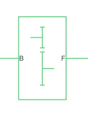
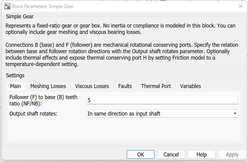
- A simple gear block is used to connect the motor to the rear axle of the vehicle.
- It represents the gearbox which connects the input shaft to the base gear and ouput from the foller gear.
- The simple gear box represents the gearbox that constrains the connected driveline axes of the base gear B and the follower gear F to corotate with a fixed ratio that is specified. Connections B which is the base and F the follower are mechanical rotational conserving ports.
Conserving Ports:
- B - port associated with input shaft (motor shaft)
- F - port associated with ouput shaft (axle / differential)
Simple Gear Parameters:
- Gear ratio and output direction is modified.
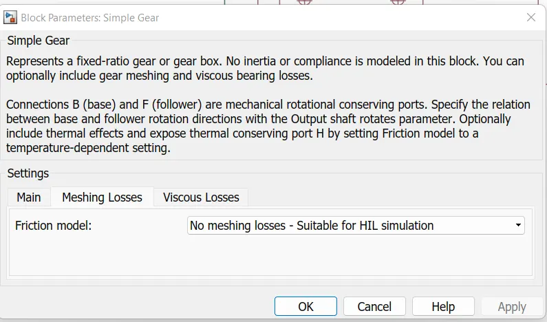
- Meshing loss is kept constant and gear is having a constant efficiency throughout the simulation.
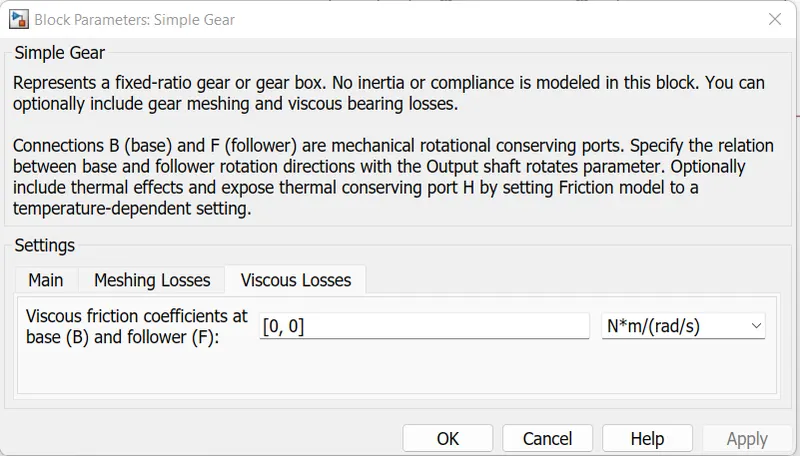
- Viscous losses and faluts are kept at default conditions.
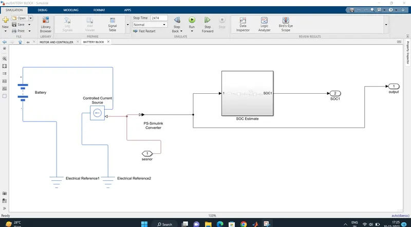
Battery Source
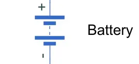
The battery is connected as the power source to the model so that the power could be generated and the same power is transmitted accordingly to all the operating sources.
The terminals connected are to,
+ = The positive terminal of the operating sources
- = The negative terminal of the operating sources.
Components of battery block is depicted below:
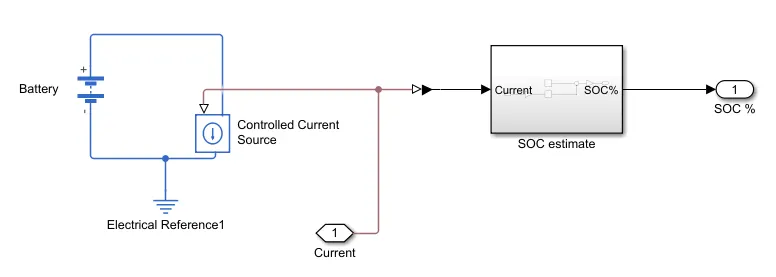
Fig L : Components of battery block
The paramters considered of the battery are -
The battery Nominal Voltage is rated as per 300 Volts,
The internal resistance is as per 0.5 Ohms and others set as default.
Battery State of Charge :
- A small subsystem is created to calculate the State of Charge of the battery.
- This subsystem takes the battery current as the input.
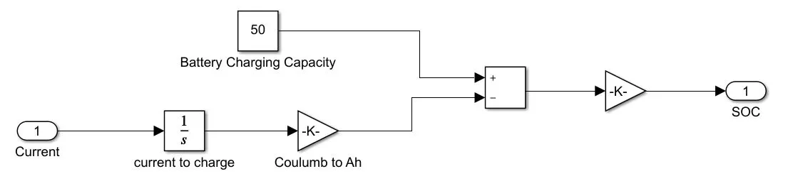
Fig M : Battery State of Charge
- The essential process to calculate the SOC is by subtracting the charge from the rated capacity of the battery.
- Accordingly, the current is integrated w.r.t. time to get the charge in coulumbs. Now this coulumb value is modified into Ampere hours.
This value is now subtracted from the charging capacity of the battery i.e. 50 Ah. - Finally, the remaining charge is now converted into percentage value of the charging capacity of the battery.
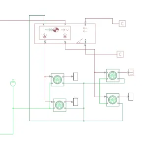
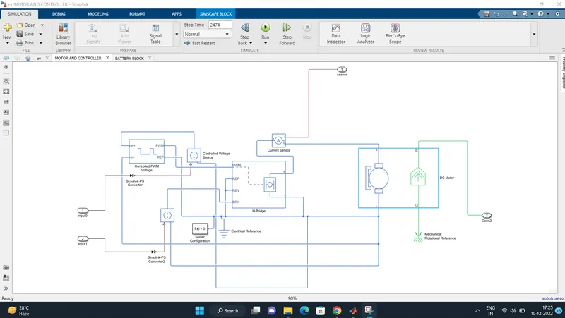
Controlled PWM Voltage
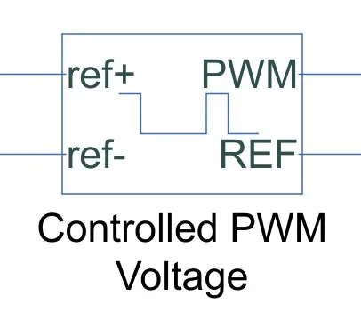
The Controlled PWM Voltage Block helps in keeping the Modulated Pulses as per the required pulses. So that the operations happens smooth and higher variations are not observed.
The Ports are connected as follows,
ref+ = Reference Positive connected with the Acceleration Commands from the Driver Model
ref- = Reference Negative connected with the Deceleration Commands from the Driver Model
PWM = PWM connected directly to the H-Block
REF = REF connected directly to the H-Block
Note :The parameters are set as default.
DC Motor
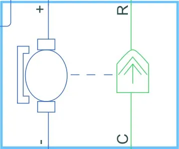
This is the DC Motor which would give the rotational power to the wheels and become the sole power generation source.
The DC Motors terminals are connected as mentioned below,
+ = Electrical signal to the motor Positive Terminal
- = Electrical signal to the motor Negative Terminal
R = Casing of the Motor connected with the Mechanical Rotational Reference Block
C = Rotor Case connected to the Mechanical Rotational reference
The parameter considered are, The Armature inductance is as default, varied the changes in the No-Load Speed 8000 rpm, the rated speed 5000 rpm, the Rated Load at 50kW, and the Rated DC Supply Voltage 300 V. All other parameters are as default.
H-Bridge
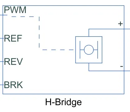
The H-Bridge helps in controlling the power that is input according to the requirement. The output provided are converted voltage as per the controlled parameters.
- VEHICLE BODY
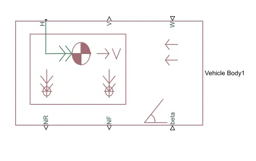
This vehicle body block is a representation of a two – axle vehicle body in longitudinal motion. The vehicle can have the same or different number of wheels on each axle. The vehicle can have a centre of gravity that is at or below the plane of travel. This block accounts for body mass, aerodynamic drag, road incline and weight distribution between axles due to acceleration and road profile which optionally includes pitch and suspension dynamics. The vehicle does not move vertically relative to the ground.
Connection H is the mechanical translational conserving port which is associated with the horizontal motion of the vehicle body. The traction motion developed by the tires should be connected to this port.
Connections V, NF and NR are physical signal output ports that represents vehicle velocity and front and rear normal wheel forces. These wheel forces are considered positive if acting downward. Connections W and beta are physical signal ports that signify headwind speed and road inclination angle respectively.
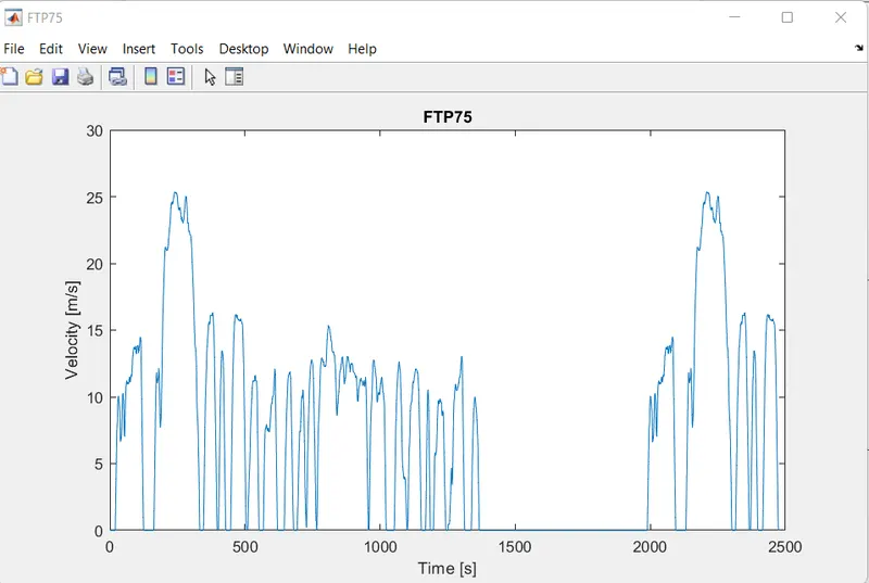
Drive Cycle Source block — FTP75 (2474 seconds) : Generates a standard or user-specified drive cycle velocity versus time profile. Block output is the selected or specified vehicle longitudinal speed.
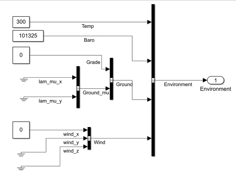
subsystem : Creates environment variables, including road grade, wind velocity, and atmospheric temperature and pressure. Longitudinal subsystem:
Uses the Longitudinal Driver or Open Loop variant to generate normalized acceleration and braking commands. Longitudinal Driver variant implements a driver model that uses vehicle target and reference velocities.
Open Loop variant allows you to configure the acceleration, deceleration, gear, and clutch commands with constant or signal-based inputs.
Sub -systems :
Vehicle body
Motor and power controlled block
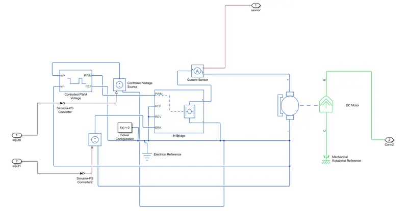
Fig M : Motor and power controlled block
Battery block :
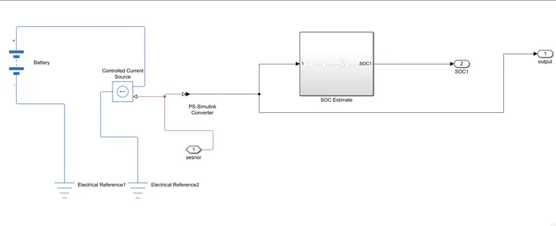
Fig N : Battery block
Evaluate and Report Power and Energy
The script provides:
-
An overall energy summary that you can export to an Excel spreadsheet.
-
Electric plant and drivetrain plant efficiencies.
-
Data logging so that you can use the Simulation Data Inspector to analyze the powertrain efficiency and energy transfer signals.
Drive Cycle Source
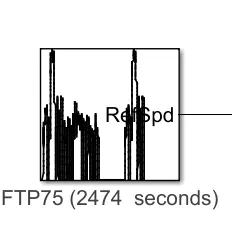
Fig O : Drive cycle source.
Generates a standard or user-specified longitudinal drive cycle. The block output is the vehicle longitudinal speed. You can import drive cycles from:
- Predefined sources
- Workspace variables, including arrays and time series objects
- mat, xls, xlsx, or txt files
Use the fault tracking parameters to identify drive cycle faults within specified speed and time tolerances.
The block generates a target vehicle velocity for a selected or specified drive cycle. The reference application has these options.
| Timing | Variant | Description |
|---|---|---|
|
Output sample time |
continuous (default) |
Continuous operator commands |
| Discrete |
Discrete operator commands |
Environment Subsystem
Creates environment variables, including road grade, wind velocity, and atmospheric temperature and pressure.
Fig P : Environment block
Longitudinal Driver
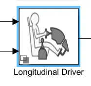
Fig : Longitudinal driver block and model
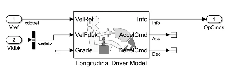
Fig Q : Longitudinal driver model
There are different commands driver can give to the vehicle likewise acceleration , Deacceleration, Also there are Velocity reference and velocity feedback commands connected to the controller from this model block.
The subsystem generates normalized acceleration and braking commands. The reference application has these variants.
|
Block Variants |
Description | ||
|---|---|---|---|
|
Longitudinal Driver (default) |
Control |
Mapped |
PI control with tracking windup and feed-forward gains that are a function of vehicle velocity. |
|
Predictive |
Optimal single-point preview (look ahead) control. |
||
|
Scalar (default) |
Proportional-integral (PI) control with tracking windup and feed-forward gains. |
||
|
Low-pass filter (LPF) |
LPF |
Use an LPF on target velocity error for smoother driving. |
|
|
Pass |
Do not use a filter on velocity error. |
||
|
Shift |
Basic |
Stateflow® chart models reverse, neutral, and drive gear shift scheduling. |
|
|
External |
Input gear, vehicle state, and velocity feedback generates acceleration and braking commands to track forward and reverse vehicle motion. |
||
|
None (default) |
No transmission. |
||
|
Sceheduled |
Stateflow chart models reverse, neutral, park, and N-speed gear shift scheduling. |
||
|
Open Loop |
Open-loop control subsystem. In the subsystem, you can configure the acceleration, deceleration, gear, and clutch commands with constant or signal-based inputs. |
||
Controllers
It is a device which improves the performance of an electric motor. It is a machine that is used to regulate the torque generated by the motors of electric vehicles. It does so by means of modifying the energy flow from the power sources to the motor. Motor controllers can include an automatic or manual means for starting or stopping the motor. It can choose forward or reverse rotation, can select and control the speed, can modify or limit the torque of the EV motor.
A simple DC controller is connected between the batteries and the DC motor. If the driver floors the accelerator pedal, the controller delivers the full volts from the batteries to the motor. If the driver takes his/her foot off the accelerator, the controller delivers zero volts to the motor.
The controller takes power from the batteries and delivers it to the motor. The accelerator pedal hooks to a pair of potentiometers and these potentiometers provide the signal that tells the controller how much power it is supposed to deliver. The controller can deliver zero power when the car is stopped and full power when the driver floors the accelerator pedal, or any power level in between.
When you push on the gas pedal, a cable from the pedal connects to these two potentiometers: The signal from the potentiometers tells the controller how much power to deliver to the electric car's motor. There are two potentiometers for safety's sake. The controller reads both potentiometers and makes sure that their signals are equal. If they are not, then the controller does not operate. This arrangement guards against a situation where a potentiometer fails in the full-on position.
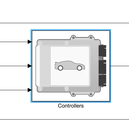
Fig R : Controllers
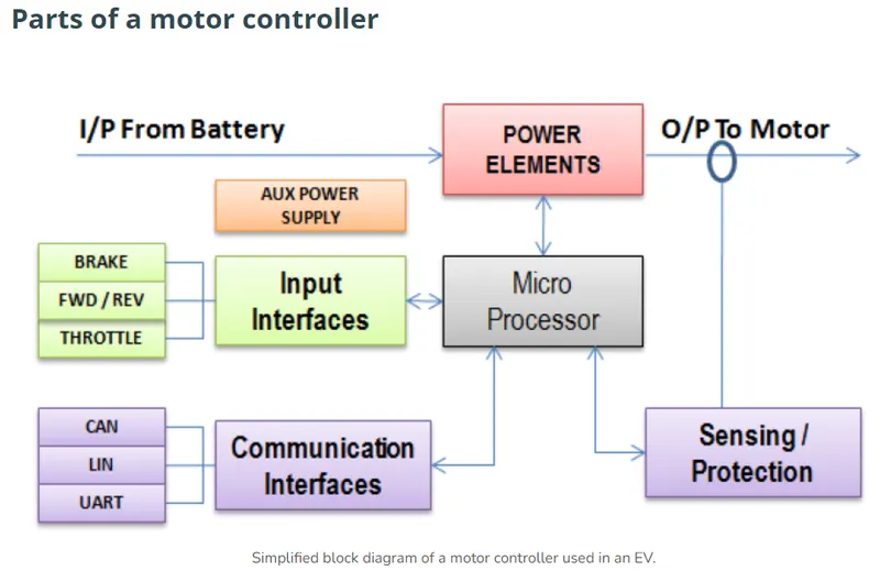
Fig R : Simplified block diagram of a motor controller used in an EV
MOTOR CONTROLLER
Motor Control Unit (MCU) is an electronic module that interfaces between the batteries and motor to control the electric vehicle’s speed and acceleration based on throttle input. The controller transforms the battery’s direct current into alternating current and regulates the energy flow from the battery. The controller also reverses the motor rotation during regen which in turn charges the battery.
Motor Controllers intended for EV application can be broadly classified into following categories: Voltage, Power & Current. The table below summarizes such specifications for different vehicle class.
MOTOR CONTROLLER OPERATION
Following Control Logic modes have been used for motor commutation:
- Trapezoidal
- Modified Trapezoidal or ‘Six-Step’
- Sinusoidal
Trapezoidal control, although easy to implement produced significant torque ripples at each commutation step and thereby, hampering efficiency.
The Torque output of a motor is maximized when the stator & rotor magnetic fields are at 90°. With Sinusoidal control, each of the motor winding getting current with a phase difference of 120° & the result is a smoothly rotating current vector with a constant magnitude that is orthogonal to the rotor. This results in the elimination of torque ripples that translate into smooth motion and precise motor control.
To determine the motor torque and brake pressure commands, the reference application implements a supervisory controller. Specifically, the controller subsystem includes a powertrain control module (PCM) with:
-
Regenerative braking control
-
Motor torque arbitration and power management
-
Converts the driver accelerator pedal signal to a torque request.
-
Converts the driver brake pedal signal to a brake pressure request. The algorithm multiplies the brake pedal signal by a maximum brake pressure.
-
Implements a regenerative braking algorithm for the traction motor to recover the maximum amount of kinetic energy from the vehicle.
-
Implements a virtual battery management system. The algorithm outputs the dynamic discharge and charge power limits as functions of battery state of charge (SOC).
-
Implements a power management algorithm that ensures the battery dynamic discharge and charge power limits are not exceeded.
-
Regen Braking Control has these variants.
| Controller | Variant | Description |
|---|---|---|
|
Regen Braking Control |
Series regenerative braking (default) |
Friction braking provides the torque not supplied by regenerative motor braking. |
| Parallel regenerative braking |
Friction braking and regenerative motor braking independently provide the torque. |
Parts of controllers are as follows:
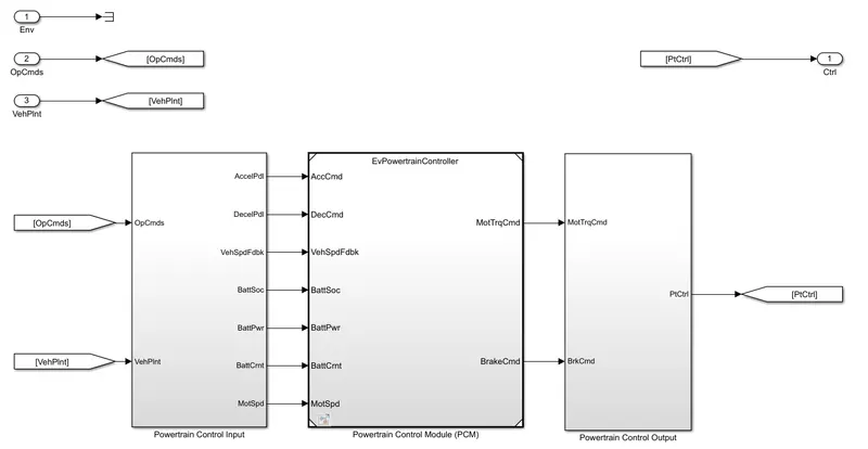
1.Powertrain control input.
2. Powertrain control module (PCM)
3.Powertrain control output.
Threre different types of ports are present in powertrain control input such as acceleration pedal, deacceleration pedal, vehicle speed feedback , battery state of charge, battery power, battery current, motor speed, Vehicle plant,output commands.
Passenger Car
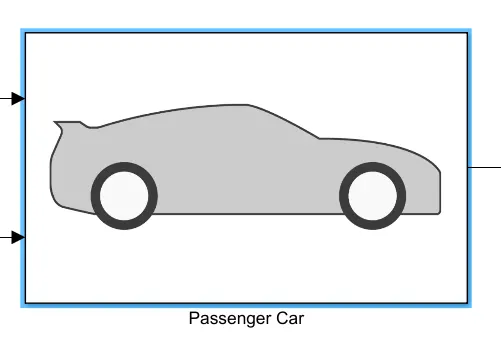
Fig S : Passenger car block
There are different types of blocks are present inside passenger car.
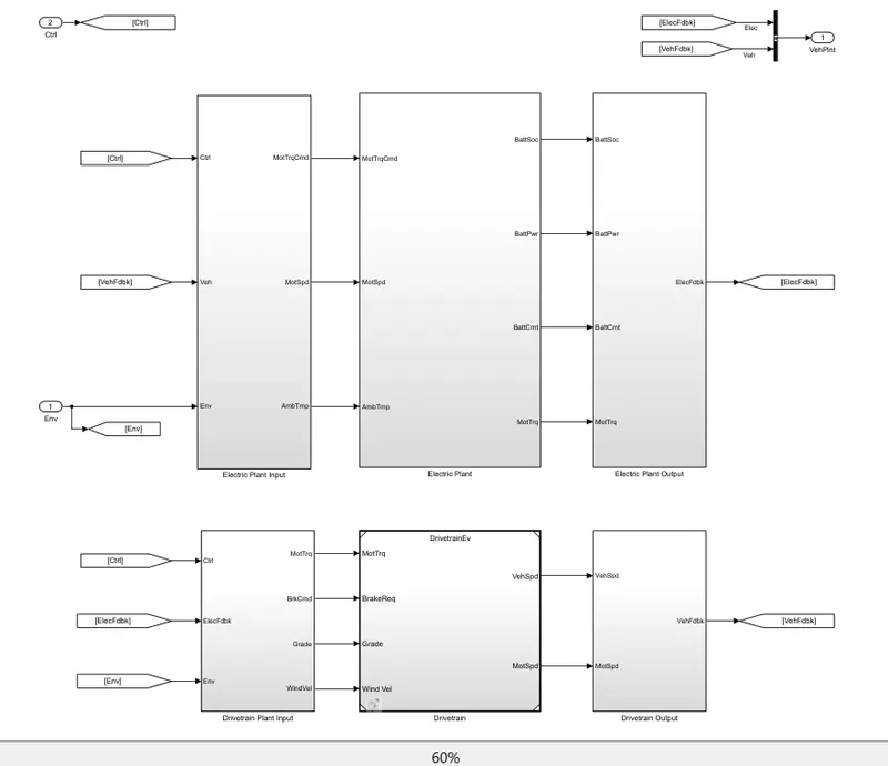
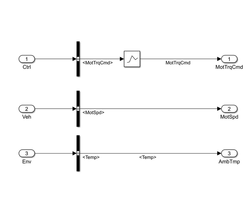
1.Electric plant input.
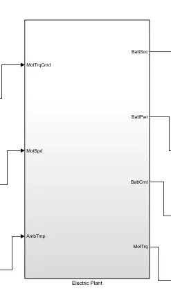
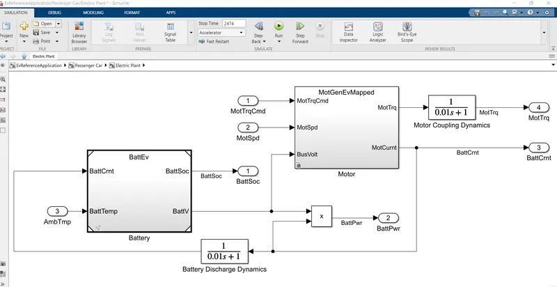
2.Electric plant.
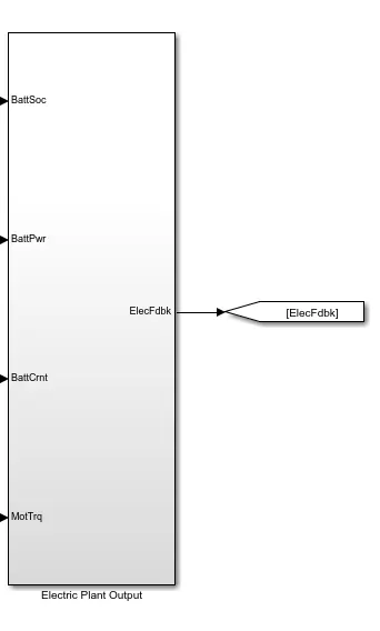
3.Electric plant output.
4.Drivetrain plant input.
5.Drivetrain.
6.Drivetrain output.
1.1.Electric plant input
2.1.Electric plant.
3.1 Electric plant output.
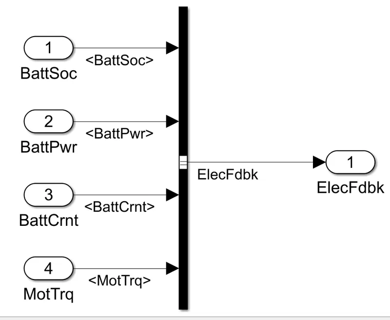
To implement a passenger car the passenger car subsystem contains a drivetrain and electric plant subsystem. The reference application has these variants.
Drivetrain
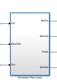
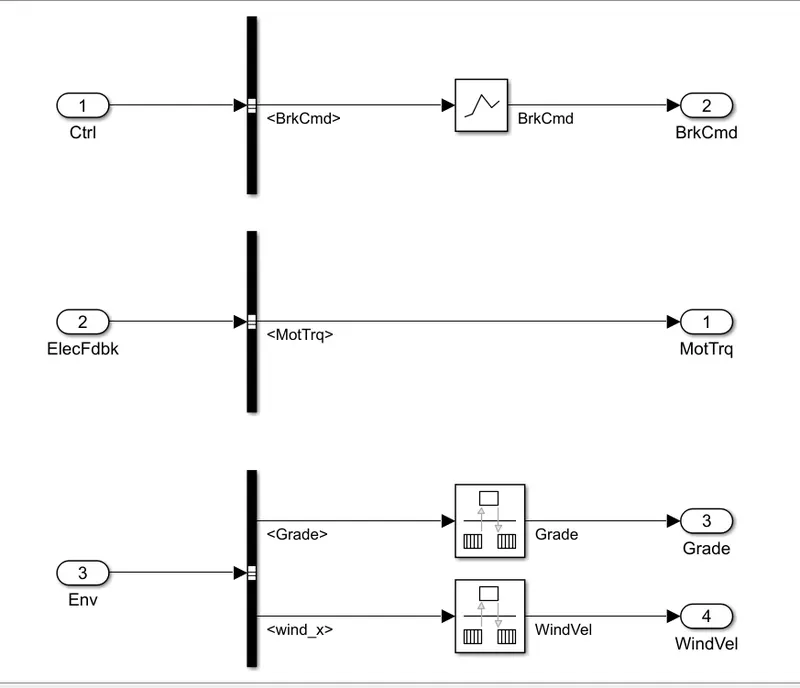
| Drivetrain Subsystem | Variant | Description | |
|---|---|---|---|
|
Differential and Compliance |
All wheel drive |
Configure drivetrain for all wheel, front wheel, or rear wheel drive. For the all wheel drive variant, you can configure the type of coupling torque. |
|
| Front wheel drive (Default ) | |||
| Rear wheel drive | |||
|
Vehicle |
Vehicle body 3DF longitudinal |
Configured for 3 degrees of freedom |
|
|
Wheels and Brakes |
Longitudinal wheel - Front 1 |
For the wheels, you can configure the type of:
For performance and clarity, to determine the longitudinal force of each wheel, the variants implement the Longitudinal Wheel block. To determine the total longitudinal force of all wheels acting on the axle, the variants use a scale factor to multiply the force of one wheel by the number of wheels on the axle. By using this approach to calculate the total force, the variants assume equal tire slip and loading at the front and rear axles, which is common for longitudinal powertrain studies. If this is not the case, for example when friction or loads differ on the left and right sides of the axles, use unique Longitudinal Wheel blocks to calculate independent forces. However, using unique blocks to model each wheel increases model complexity and computational cost. |
|
|
Longitudinal wheel - Rear 1 |
|||
Electric Plant
| Electric Plant Subsystem | Variant | Description |
|---|---|---|
| Battery |
BattEV (default) |
Configured with electric battery |
| Motor |
MotGenEVmapped (default) |
Mapped motor with implicit controller |
|
MotGen EV Dynamic |
Interior permanent magnet synchronous motor (PMSM) with controller |
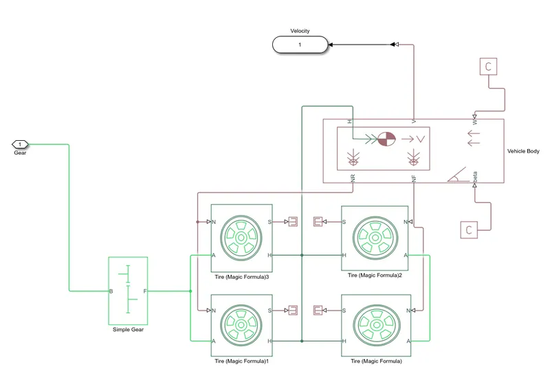
EXPLANATION OF VEHICLE BODY SUBSYSTEM
- Transmission is an important aspect of the vehicle which is used to supply the propulsion power from the motor and then the wheels.
- For the creation of the above subsystem the following blocks that were used were Tire (Magic formula) block, simple gear block and vehicle body so as to create the base for the model.
- Firstly, the wheels of the vehicle are modelled by using the Tire block. Four tire blocks ae created for the vehicle and named them as front and rear wheels.
- For the tire block there are various parameters which can be edited according to the requirement. During the simulation default parameters of the tire block were used.
- Then all the ports of each tire block are connected with each other. Port A represents axle so the rear wheels A ports are connected with each other which signifies that they are on the same axle. Similarly, the front wheels are also connected to the same axle.
- Then the H port represents the hub and all the H ports are connected to each other.
- The N and S port represents the normal force and slip of the tire respectively. So, the normal force on the rear wheels is the same, so the N port of both rear wheels is connected with each other and similarly for the front wheels normal force. The port S represents the slip occurring in the wheel. The port can be connected or can be ignored. In the above model it is connected to a PS Terminator block which terminates the physical signal outputs.
- Then a vehicle body diagram is used which represents the vehicle dynamics where there are various parameters which can be changed according to the requirement.
- The NR and NF port in the vehicle body represents the normal force on rear and front tires respectively. So, the N port of the front and rear tires are connected with NR and NF ports accordingly.
- The H port in the vehicle body is associated with the horizontal motion of the body and is connected to the H port of all the tires.
- The W and BETA port represents the wind speed and road inclination angle which can be entered as an input. In the above model the W and the BETA port are connected to a PS constant block since we have assumed both to be zero.
- The port V in the vehicle body represents the velocity output from the vehicle. So, this is connected to the output port. Since the power from the motor has to be transmitted to the wheels a transmission block is used which is a SIMPLE GEAR BLOCK. This block is connected to the rear wheel axle since the model is considered as a rear wheel drive.
- Finally, the subsystem is modelled where the input of the system is the power given to the simple gear box and output is the velocity of the vehicle.
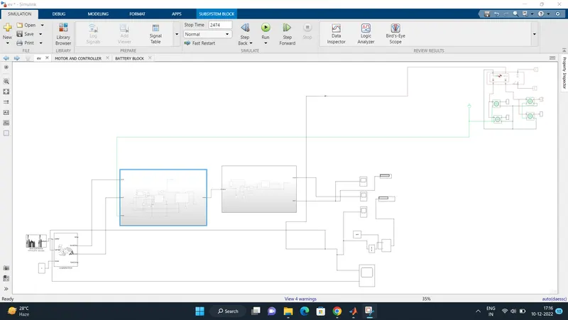
The complete subsystem is shown below
SOC & Distance travelled.
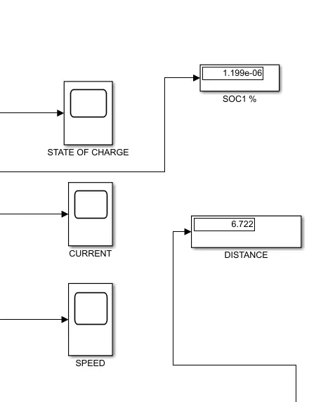
Outputs :
Battery State of Charge
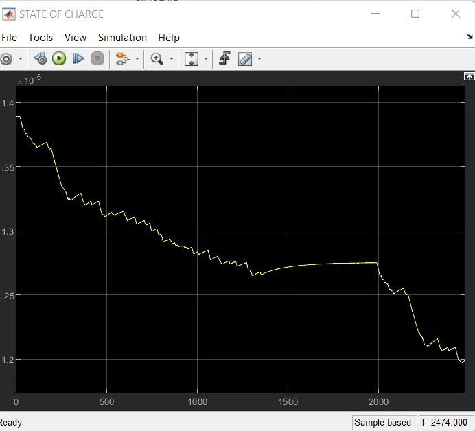
- The State-of-Charge of the battery at the end of simulation run is nearly about 77 %.
- This means that the battery is not completely drained at the end and the vehicle can run on the same drive cycle for a few more times before the battery SOC becomes 0.
- Also, the thing to be noted here is, since we had enabled the regenerative braking for the simulation, the battery SOC increases slightly whenever the vehicle undergoes heavy deceleration.
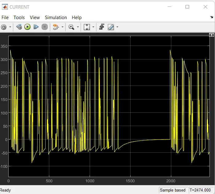
- Again, this depends upon the generating tendency of the motor and the maximum amount of current that the battery can take.
Battery current
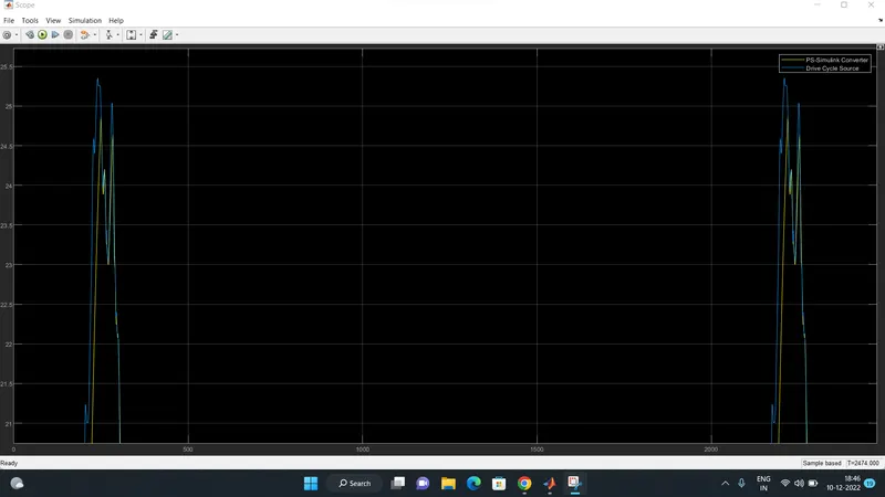
Speed

- It may be noted that, since, the reference velocity of the drive cycle never becomes negative (i.e. there is no backward motion of the vehicle), the distance is increasing throughout.
- The total distance covered by the vehicle is about 6.7 km.
CONCLUSION : The model was succesfully ran for simulation under the standard FTP75 drive cycle. The results have been properly analyzed.
Also, learnt quite a lot of interesting things like -
- how to model an EV and carry out a real time simulation
- how a motor controller works and what role it plays in the control of the electric motor
- how to calculate the SOC of the battery
- different powertrain blocks provided by simulink which can be used to simulate a vehicle model.