Design of an Electric Vehicle
AIM: To create a MATLAB model of electric car which uses a battery and a DC motor.
Theory:
A vehicle that substitutes an electric motor or traction motor for the internal combustion engine found in traditional automobiles is referred to as an electric vehicle (EV). Unlike traditional automobiles, electric vehicles run on electricity rather than fossil fuels. Therefore, they don't emit any pollutants or exhaust gases. Batteries, generators, or any other collector system provide the necessary power for the EV. For the EV to provide the necessary power and range, high energy density batteries are used.
Like in conventional cars, the electric motor power of a vehicle is expressed in kilowatts (kW). However, electric motors may provide their maximum torque over a wide RPM range, so 100 kW is roughly equivalent to 134 horsepower. This means that a vehicle with a 100 kW electric motor performs better than a 100 kW internal combustion engine, which can only produce its maximum torque over a narrow speed range. The process of converting electrical energy to mechanical energy results in energy loss.
90% of the battery's energy is transferred to mechanical energy, with the motor and drivetrain suffering the losses. Typically, (DC) electricity is used to power a 3-phase AC motor before being converted to (AC) electricity in a DC/AC inverter. DC motors are frequently used in electric trains and some electric vehicles. It is possible to use AC or DC after using universal motors in specific circumstances. Various motor types have been used in recent mass-produced vehicles, including permanent magnet machines in the Nissan Leaf and Chevrolet Bolt and induction motors in Tesla Motors' vehicles.
The majority of large electric transportation systems are powered by fixed electrical sources that are wired directly to the vehicles. Regenerative braking, which turns the motors into generators that convert the motion of a train, typically, into electrical power that is then fed back into the lines, is made possible by electric traction. This system is especially helpful for operations in mountainous terrain because descending vehicles can generate a significant amount of the power needed for ascending ones. Only if the system is large enough to use the power generated by descending vehicles will this regenerative system be functional. There must be more convenient ways for consumers to charge their vehicles if electric vehicles are to rule the automotive industries. The need for numerous charging stations on highways can be met if the majority of homes are powered by solar energy. Because batteries and other electric components are more expensive than those in conventional vehicles, EVs are more expensive.
HEVs create a hybrid between the two types of vehicles by combining an IC engine with an electric propulsion system. The idea behind this is to use the power offered by the electric powertrain to increase the vehicle's fuel efficiency so that it does not solely rely on gasoline or diesel for fuel. In turn, the HEV's overall performance will be enhanced. The IC engine can be directly used in the electric drive motor with a combination of motor and generator in one, or it can be used to power the electric motor to charge the battery. Regenerative braking is another technique used by HEVs to replenish their batteries. EVs still represent 2-3% of the global market and are a relatively new technology. HEVs, on the other hand, account for a larger market share with a 19% market share across all autos. The Toyota Prius is the HEV that has sold the most units overall.
Using the SIMULINK software, we will model an electric car with a DC motor and battery system for this report. The model will run for a drive-cycle and measure the battery system's state of charge, current, and velocity characteristics. The blocks we require are present in the Simulink block library.
Components:
The following are the EV's primary parts:
- Wheels/tires
- Battery
- Motor/generator
- Motor controllers
- Power converters
- transmission mechanism
Simulation diagram:
We simulated an electric vehicle utilising different drive cycles in the image below using the powertrain blockset from the Simulink library.
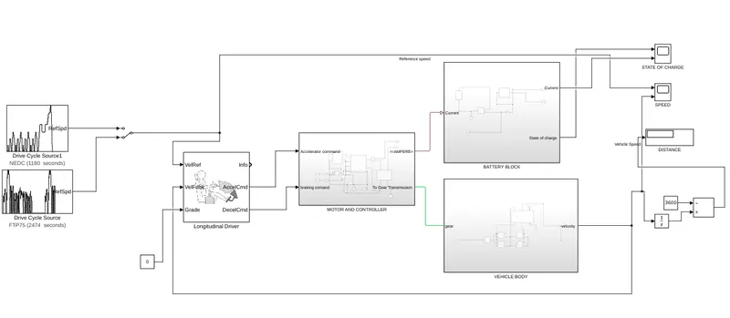
The inputs, where we linked two separate driving cycles, serve as a starting point for the longitudinal driver, which compares the two speeds and instructs the motor controller block to accelerate and brake. Additionally connected are the battery block and vehicle body blocks, and scopes are used to show the operational status.
Configuration at the system level:
To model the above-mentioned components individually and have them function as a unit in SIMULINK, we must first model the entire vehicle.The library of SIMULINK blocks contains all the essential parts. So, to match the model's operational requirements, we add components and set the parameters.
Vehicle body
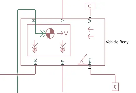
Six ports on this block can be utilised to model different parts of the vehicle body. Below are the ports mentioned;
- The letter H, which stands for hub, is used to join the wheel hubs to the vehicle's main body.
- The vehicle's velocity is output using the "velocity"-designated V-Physical signal output port.
- W- Physical signal input port that enables us to simulate the wind speed that opposes the vehicle.
- A physical signal output port to link the back wheels is designated as NR.
- NF: A physical signal output port used to connect the vehicle's front wheels.
- Beta: A physical signal input port that enables the vehicle to climb hills with an inclination.
- Set up the mass, frontal area, and other model parameters.
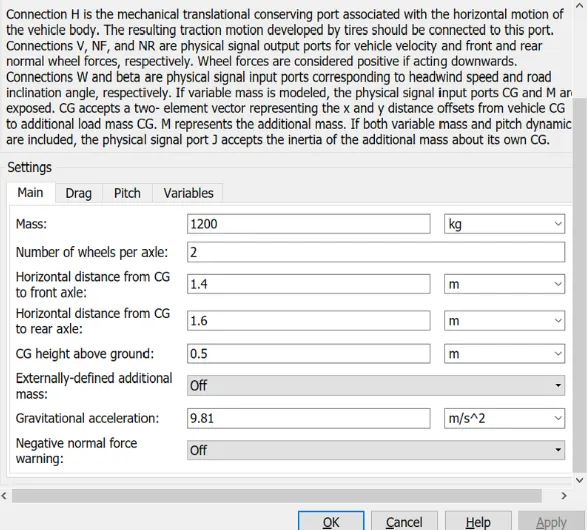
Vehicle body
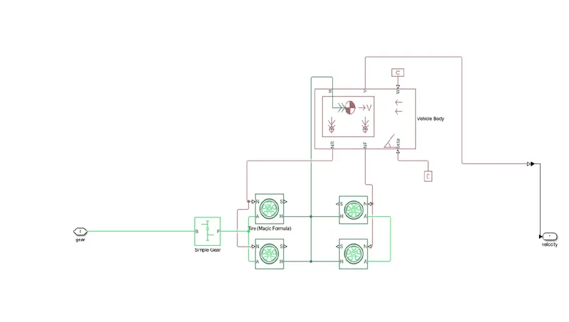
The building components mentioned above come together to form a part of the vehicle's overall subsystem. There are four connected tyres, the remaining two being the front wheels and the right two being the rear wheels. To the hub of the vehicle body block, they are attached. and the appropriate connections are made between each axle. As the model is intended to be a rear-wheel drive car, we have here connected the rear axle with the gear. The physical constant blocks that are kept at zero in this situation are connected to the ports for the wind speed and hill-climbing angle.
Tire block
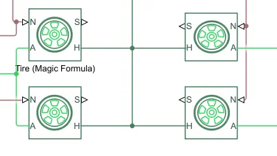
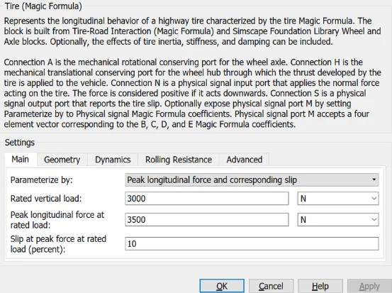
Additionally, if desired, we can alter the geometry, dynamics, and other features here.
Simple gear block
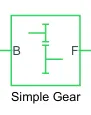
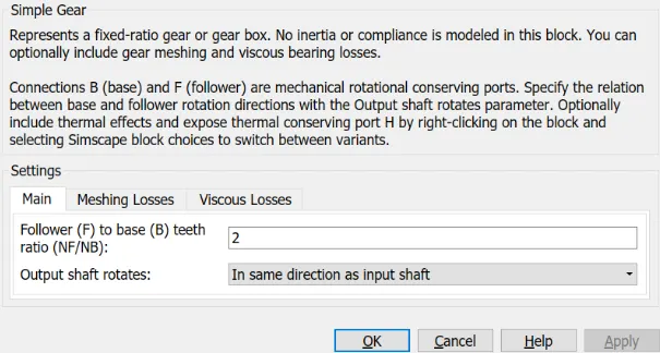
This block simulates a fixed gear ratio, no-inertia gear system. However, we can change the way the gear teeth are arranged here. The output shaft rotates in the same direction as the input shaft, and the follower to base teeth ratio is set to 2.
All of these components are grouped together into a single subsystem called the vehicle body block, which receives mechanical input from the controller and motor blocks, drives a gear, and displays the speed at which the vehicle body is moving.
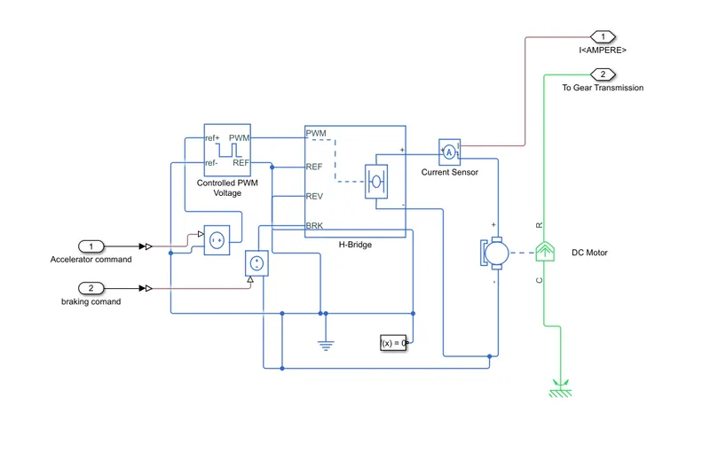
Subsystem of Motor and Controller
Components:
- H-bridge for DC motors
- Controlled PWM voltage
- Controlled voltage source
- Current sensor
DC-Motor
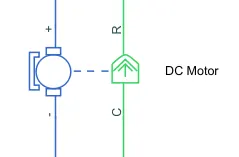
I decided to use a DC motor block for the EV model since DC motors are simple to build and only require a small number of operating parameters. The mechanical side is on the right side of the block, and the electrical side is on the left. Tow ports C and R are located on the mechanical side; C stands for the casing, which is the stable component, and R is the rotor, which generates torque. For the application of voltages, the electrical side has positive and negative sides. A positive torque will act from the C to R port if positive voltage is applied to the motor block from the positive to the negative terminal.
By altering the sign of the back emf or the torque constant, the direction of the torque can be changed. Because it will be stationary, I have here connected the C port to the mechanical rotating reference. The gear in the vehicle body block is connected to the R port.
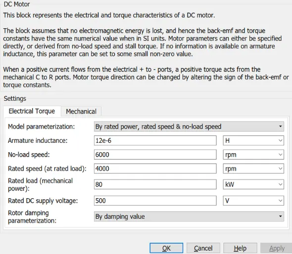
In this case, I've decided to parameterize the block according to the rated power, rates speed, and no-load speed. This enables us to change the settings, such as the rated load and DC supply voltage. With the exception of the no-load speed, rated speed, and rated load, I've left all parameters at their default values.
H-Bridge
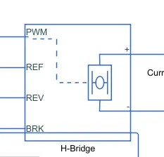
This power converter is required to transfer electricity from one component to another in the right form and amount. In the case of electric vehicles (EVs), a power converter is required to supply a DC voltage from the battery of the EV to the DC motor in order for it to operate correctly at the necessary parameters. Here, my power converter is an H-bridge motor drive. The left side ports are used to control voltage signals, and the right side terminals supply the controlled voltage to the DC motor. Ports here are
- Pulse width modulation (PWM)
- REF-Reference
- BRL- Brake
- REV- Reverse
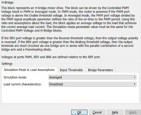
The simulation remains in the typical setting. because PWM mode requires longer simulation times. The output voltage amplitude was changed to 400 volts in the bridge parameters section to accommodate the DC motor.
Controlled PWM
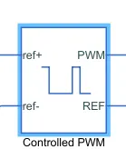
Next, I utilised a "controlled PWM voltage" to give the H-bridge block a controlled pulse width modulated voltage. The duty cycle, which is the ratio of the time the switch is ON to the time it takes to complete one cycle, determines the voltage pulses that are produced by this block. Duty cycle is calculated as follows: Duty cycle = Ton/Ton + Toff = Ton /Tcyc, where Ton stands for On time and Tcyc for cycle duration.
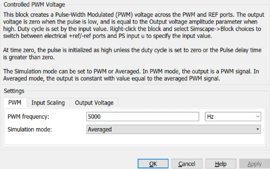
Here, every parameter is set to its default setting. I have selected the averaged simulation mode so that it will supply voltage pulses to the H-bridge within shorter simulation times. Input and output scaling's remaining variables remain the same.
Controlled voltage source
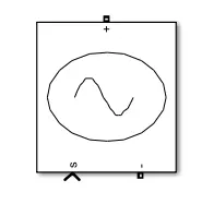
This block supplies the necessary voltage that is strong enough to keep the output voltage constant no matter how much current flows through it. Blocks with a control voltage have been employed in this subsystem. The voltage for deacceleration is provided by one block, while the other is used for acceleration.
For electrical circuits, a grounding effect is produced using an electrical reference block. We have used it in two pieces in my model. The first step is to establish an electrical ground between the H-bridge blocks and the controlled voltage source, controlled PWM voltage. The following model is for the battery system, which is the second.
Any required equations in a model are solved using the solver configuration block. They were utilised in my connection to the H-Bridge block's REV port.
Subsystem of Battery:
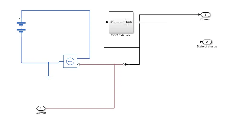
Battery: The EV's energy source will be its battery, which will store its electrical energy in DC form and supply it for operation.
Internal resistance has been set at 0.2 ohms, the nominal voltage is 600 volts, and the charging capacity is limitless.
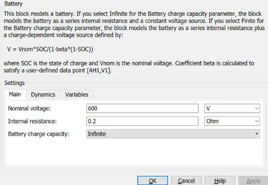
For supplying the voltage to DC-motor and H-bridge blocks, nominal voltage is adequate.
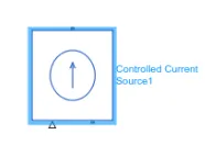
A component of the battery sub-system is this block. This block creates an ideal current that is strong enough to sustain the set current independent of the voltage across it, similar to a voltage source.
Current Sensor:
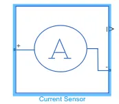
The current detected in an electrical circuit is converted into a physical signal that is proportionate to the current using this current sensor block, which is an ideal current sensor. It measures both the DC motor and battery circuit current. the positive and negative terminals that are used to connect the current sensor to the circuit. In my model, the third port outputs the physical signal, which is sent to the controlled current source.
SOC estimation:
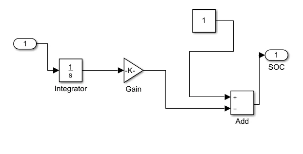
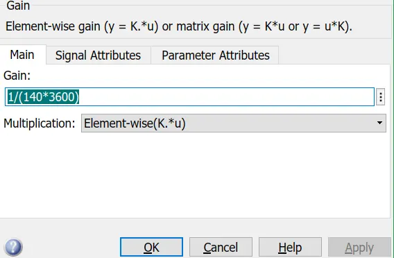
To measure the state of charge of the battery, a sub-system was created of various blocks. The first block is integrator block used to handle data transfer and integrate the value of the current signal with respect to time and next is the Gain block is used in order to multiplyer divide the signal coming from integrator block. This block will divide the current signal with the ampere ratingof battery which is 140(Ah)*3600(secs in hour) . Assuming the battery is always fully charged I have added the constant block with a value of 1 representing 100%.Next a sum block is used to perform addition and substraction operations athese blocks aremade into a subsystem called SOC estimate. A scope block is used at the junction of the PS-simulink converter block to plot the output signall of the current from the battery. The output signal of the current from the battery is plotted using a scope block at the junction of the PS-Simulink converter block.
Gain block block parameters:
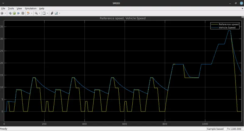
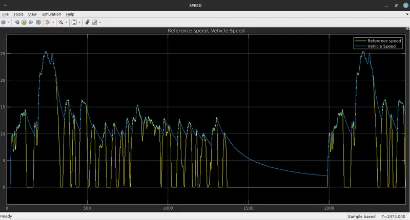
The scope block has been modified to include two input ports, one of which accepts the output velocity signal from the vehicle sub-system block and the other of which accepts the output signal from the drive cycle to the reference velocity port on the longitudinal driver block. This was done to compare the two speeds and see if they coincided with one another and reached the same pace.
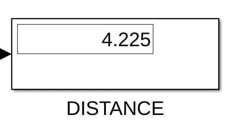
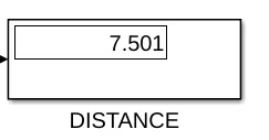
The distance covered by the vehicle is calculated using mathematical building blocks and scope blocks. To integrate the velocity signal output from the velocity sub-system, we first had to implement the integrator block. To split the integrated speed, a divided block and a constant block with a value of 3600 are needed. This will provide us with the kilometres travelled.
Longitudinal driver and drive cycle:
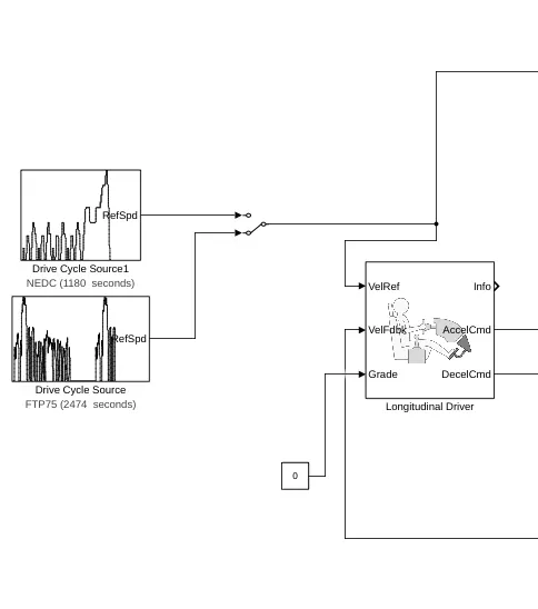
The longitudinal driver block is used to provide two sets of data-based normalised acceleration and deacceleration commands to a controller. The reference velocity is the first set of data, while the feedback velocity is the second. The feedback velocity data from the vehicle body is compared to the reference velocity data from the drive cycle source. The regulated voltage source will get an acceleration command if the reference velocity is higher than the feedback velocity. A deacceleration instruction is issued to another control voltage source if the reference velocity is lower than the feedback velocity. I utilised the Simulink-PS converter block for the output acceleration and deacceleration instructions. In this instance, the incoming signal is velocity data, which must be transformed into a voltage signal. These ports make up this block:
- The term "Velref" refers to the reference velocity, which is the velocity information given from a driving cycle source.
- Velfdbl, which stands for feedback velocity, is coming from the body velocity port of the vehicle.
- Grade: This port indicates the vehicle's grade, or angle of inclination, in degrees.
- Information: This port is for the block computations' bus signalling.
- A controlled voltage source receives the acceleration instruction from this port, which is called Accelcmd.
- Deacclcmd- This port gives another voltage source the deacceleration command.
Drive cycle:
To model a vehicle's motion, a drive cycle is a set of data that includes velocity and time information. It is a plot of the vehicle's speed against time that has been created to mimic realistic driving situations that customers might encounter. The "NEDC cycle" and the "FTP75" are two examples of the drive cycle data that I used in this example. Drive cycles are employed in a number of testing processes, including mileage, pollution, acceleration, and top speed tests.
Results:
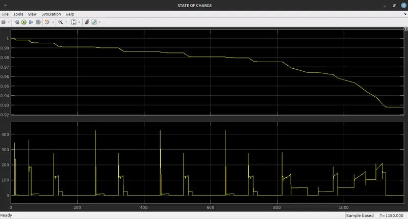
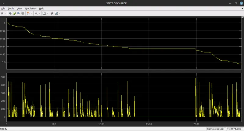
Using my EV model, I executed the aforementioned drive cycle and recorded the outputs from the speed, current, and SOC scopes. Using the display block, the vehicle's distance travelled throughout the drive cycle is also calculated. The run time was adjusted before to simulation in accordance with the driving cycle time.
For NEDC cycle for a simulation time of 1180 seconds
Battery SOC and current
Reference speed and Vehicle speed
Distance travelled
For FTP75 drive cycle for a simulation time of 2474 seconds
Battery SOC and current
Reference speed and Vehicle speed
Distance travelled
Conclusion:
- In comparison to FTP 75, the NEDC cycle travels less distance and incurs less SOC depreciation since the drive cycle is shorter.
- Due to the nature of the drive cycle, the current varies with drive cycle and exhibits larger current spikes in FTP75 than NEDC.