Final Project: Design of an Electric Vehicle
Introduction :
And electric vehicle is a vehicle that uses electric motors for propulsion. This type of vehicles use electricity instead of fuels. Because of this, electrical vehicles do not produce any exhaust gases or pollution.
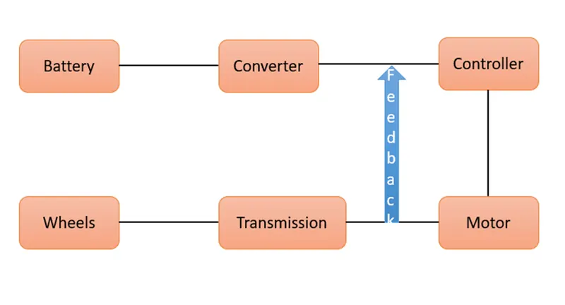
Components of an EV :
An electric vehicle has 3 major components. They are battery, controller and electric motor.
1.Battery
Battery is a device that stores chemical energy and convert it into electrical energy. The chemical reaction in a battery involves the flow of electrons from one electrode to another through and external circuit. The flow of electrons provide an electric current that can be used to do work.
Types of battery technologies :
Lead acid battery
- These are a kind of wet cell battery and usually contain a mild solution of sulphuric acid in an open container.
- These batteries are high powered, inexpensive, safe and reliable.
- Main disadvantage of these batteries are short life span and poor cold temperature performance.
Lithium ion battery
- Lightweight and low maintenance requirements.
- High weight to power ratio, high efficiency, good high temperature performance, low self discharge, cheap to produce.
- If this type of battery is overcharged, there is a risk of explosion.
Nickel metal hydride battery
- They have high energy density.
- They don’t have any toxic metals, so they are easy to recycle.
- They have longer life cycle than lithium ion or lead acid batteries.
- The main disadvantages are they are high cost, high self discharge rate. And the fact that they generate significant heat at high temperature. And they are less effective for rechargeable electric vehicles.
2.Motor controller
Motor controller is a combination of power electronics and embedded micro computing elements which make the efficiency conversion of energy stored in the batteries of an electric vehicle to generate motion.
3.Electric motor
Mostly 2 types of motors are used in EV. They are BLDC an Induction motor. BLDC is a DC motor. If we use BLDC motor then we have to use Chopper as a converter. If we use AC induction motor then we have to use inverter in place of converter.
Components used in simulation of an EV :
1.Vehicle body
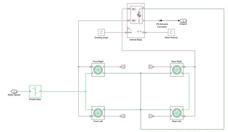
This represents a 2 axle vehicle body in motion. This accounts for body mass, aerodynamic drag grade and centre of gravity of the vehicle body.
Input ports
W – wind velocity
Beta – grade angle
Output ports
V – velocity in m/s
NF - Normal force on front axle
NR – Normal force on rear axle
Vehicle body parameters are taken as default
Tires
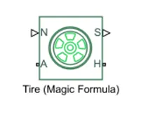
Input ports
N – Normal force acting on tire
Output ports
S – Slip related to tire and contact surface
Conserving ports
H – Represents wheel hub
A – Represents alxe
Gear
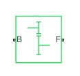
Conserving ports
S – Port associated with input shaft
O – Port associated with output shaft
2.Motor
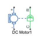
This is the DC motor which would give the rotational power to the wheels. The DC motor terminals are connected as
+ve to the +ve electrical signal
-ve to the -ve electrical signal
R port is the rotational output of the motor
C is the casing of motor and is connected to the mechanical rotational reference
3.Motor controller
H bridge block together along with inbuilt PWM block, together considered as a motor controller
H – bridge
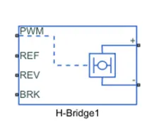
This block represents an H Bridge motor drive. The block can be driven by controlled PWM voltage block in PWM or averaged mode.
In PWM mode, the motor is powered if the PWM port voltage is above the enabled threshold voltage.
In averaged mode, the PWM port voltage divided by PWM signal amplitude parameter defines the ratio of the on time to the PWM period.
Here PWM is connected to the PWM block (pulse input).
REF is for the reference input. This is combined with PWM reference. Here references input is connected to the electrical reference.
REV corresponds to the reverse motion of the vehicle. This port is connected to the electrical reference.
BRK is for the braking of the vehicle.
PWM block
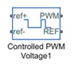
This block is used for providing the proper pulse input to the H bridge circuit.
Pwm and REF connections are for the corresponding ports on the H Bridge circuit.
The 2 reference inputs correspond to the throttle input given by the driver. The block generates corresponding pulse width as per the acceleration and brakes applied by the driver himself.
4.Longitudinal Driver
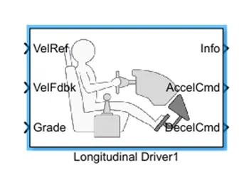
This is an inbuilt block provided by the power train block set.
The VelRef port is reference velocity port where the input drive cycle data is fed.
VelFdbk port corresponding to the feedback velocity. The actual velocity output given by the vehicle body is connected here. By comparing the feedback velocity with the reference velocity, the driver block generates acceleration and breaking signals.
Grade corresponds to the great angle in the simulation. We consider grade angle as zero.
Info gives the output for the bus signal for different block calculations like difference in reference, vehicle speed and vehicle speed etc.
Accelcmd & Decelcmd are the acceleration and deceleration. Commands generated respectively. These are connected to the corresponding parts of the control PWM voltage block.
Hear the selected controller type is PI.
5.Battery
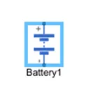
A simple battery block is used as battery. If a generic battery block is used then the simulation will run for much longer time.
The battery charge capacity is finite. Nominal voltage is taken as 400. Ampere hour rating is assumed to be 50. All the remaining parameters are default. A current sensor and controlled current source is connected to the battery to ensure that it supplies as per the requirements of the motor.
6.Drive cycle
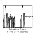
I considered a FTP 75 drive cycle for the operation of the cycle in which the test duration would be 2464 seconds.
7.SOC
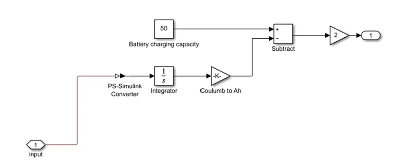
A small subsystem is created to calculate the state of charge of the battery. This system takes battery current as the input. The current is then integrated with respective to time to get the charge in Coulombs. Now this column value is modified into ampere hours. This value is now subtracted from the charging capacity of the battery, that is 50 amperes. Now the remaining charge is converted into percentage value of the charging capacity of the battery.
A solver configuration is added to solve mathematical values
Simulation
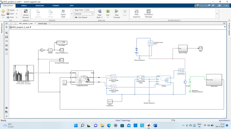
(The simulink model file is attached below for reference)
Simulation is done for 2464 seconds. Scopes are connected to analyse different outputs such as SOC, battery reference, distance covered by the vehicle. Distance is calculated by integrating velocity.
Outputs
1.Ref speed vs actual vehicle speed
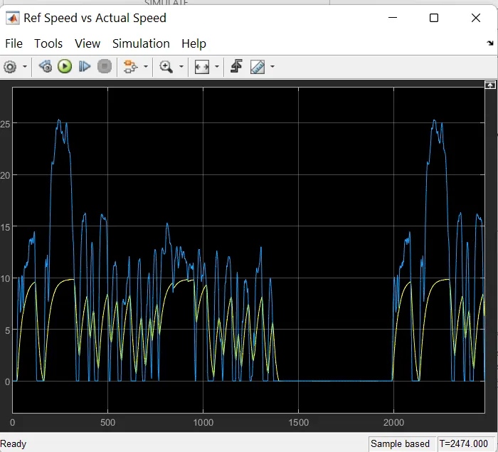
From this we can say that the actual velocity of the vehicle is differs from the reference drive cycle velocity. This is because the chosen battery capacity and motor are not able to properly the speed up to require the extent. If a battery of higher capacity issues and then the actual velocity will tend to match with reference velocity.
2.Distance covered by vehicle
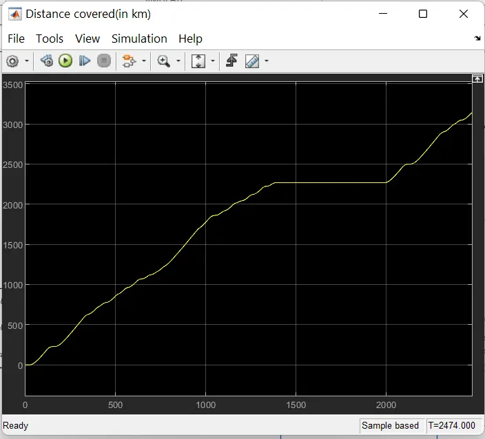
Since the reference velocity of the drive cycle never becomes negative, hence the distance is increasing throughout(that is there is no backward motion)
3.Battery State Of Charge
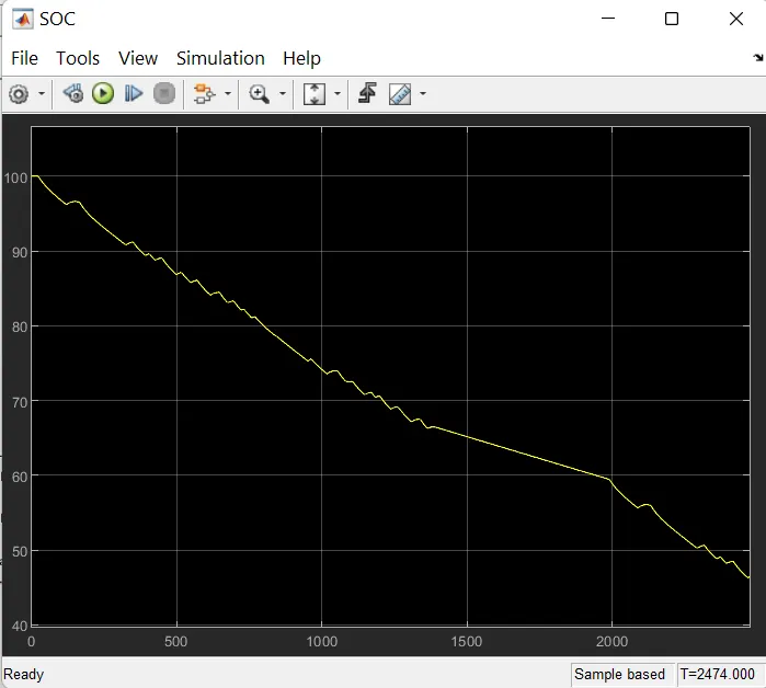
The state of charge of battery at the end of simulation is nearly 47%. This means that the battery is not completely drained at the end and the vehicle can run for a few more minutes before the SOC becomes zero.
Conclusion
The model was successfully rain for simulation under FTP75 drive cycle. The results have been properly analysed.
Things learned in this project are
- How to model an EV and carry out a real time simulation.
- How to calculate the SoC of a battery
- Different powertrain blocks provided by sibling which can be used to simulate a real time vehicle.