Final Project: Design of an Electric Vehicle
Aim: To Design A Electric Car which uses a battery and DC motor chosing a suitable blocks from Power train Blockset.
abstract: With ever-increasing concern on energy diversification, energy efficiency, and environmental protection, electric vehicles (EVs), including pure electric vehicle (PEV), hybrid electric vehicle (HEV), and fuel-cell electric vehicle (FEV) are becoming attractive for road transportation. Although some of them have become commercially available, there are many challenges and hence opportunities for EV research and development. An electric vehicle(EV) is defined as a vehicle that uses an electric motor or a traction motor for propulsion instead of internal combustion used by conventional vehicles. Electric vehicle use electricity for power instead of fossil fuels like conventional vehicles . So, they do not produce any exhaust gases and pollution. The power needed in the EV come from batteries, generator or any collector system. Batteries fitted in the EV are of high energy densities in order meet the power requirements and range. The power of a vehicle's electric motor, as in other vehicles, is measured in kilowatts (kW). 100 kW is roughly equal to 134 horsepower but electric motors can deliver their maximum torque over a wide RPM range. This means that the performance of a vehicle with a 100 kW electric motor exceeds that of a vehicle with a 100 kW internal combustion engine, which can only deliver its maximum torque within a limited range of engine speed. Energy is lost during the process of converting the electrical energy to mechanical energy. Approximately 90% of the energy from the battery is converted to mechanical energy, the losses being in the motor and drivetrain.Usually, (DC) electricity is fed into a DC/AC inverter where it is converted to (AC) electricity and this AC electricity is connected to a 3-phase AC motor. For electric trains, and some electric cars, DC motors are often used. In some cases, universal motors are used, and then AC or DC may be employed. In recent production vehicles, various motor types have been implemented; for instance, induction motor within Tesla Motor vehicles and permanent magnet machines in the Nissan Leaf and Chevrolet Bolt. Most large electric transport systems are powered by stationary sources of electricity that are directly connected to the vehicles through wires. Electric traction allows the use of Regenerative braking, in which the motors are used as brakes and become generators that transform the motion of, usually, a train into electrical power that is then fed back into the lines. This system is particularly advantageous in mountainous operations, as descending vehicles can produce a large portion of the power required for those ascending. This regenerative system is only viable if the system is large enough to utilise the power generated by descending vehicles. In order for EV,s to dominate the automotive industries, Their needs to be more convinient ways for consumers to be able to charge their vehicles. There needs to be several charging stations on highways and this can be supported if most of the houses are solar powered. EV,s cost more than conventional vehicles because of the high cost of batteries and electric components.
Power Train of the vehicle:
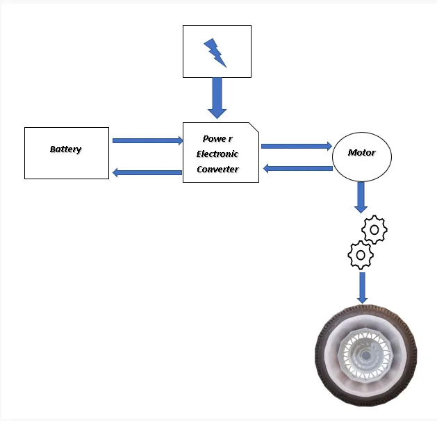
The Above Block diagram represents the power train of the electric vehicle vehicle let us start modeling an vehicle body by calculating forces acting on a vehicle.
Forces Acting on a vehicle:
The forces acting on a vehicle is calculated using a MATLAB programme shown below
clear all
close all
clc
urr = 0.013; %rolling resistance coefficient

m = 1300; %Total Gross weight of the vehicle
g = 9.81; %gravitational constant

Frr = urr*m*g; %rolling resistance force

rho = 1.25; %Air density in kg/m^3
A = 3.21; %frontal area of an ideal SUV
Cd = 0.15; %Air drag coefficient
v = 27.7778; %velocity of the vehicle in mps
Fad = (1/2).*rho.*A.*Cd.*v^2; %Air drag force

phi = 0.523599; %slope angle in radians
Fhc = m*g*sin(phi); %Hill climbing Force

vi = 0; %Initial Velocity
vf = v; %final velocity
dv = vf-vi; %change in velocity
dt = 40; %time taken to accelerate in seconds
a = dv/dt; %acceleration of the vehicle
Fla = m*a; %linear acceleration Force

FT1 = Frr+Fad+Fhc+Fla; %Total force acting on a vehicle in linear acceleration

r = 0.782; %radius of the wheel in meters considered wheel code 275/50 R 20
Tw = FT1*r;%wheel torque

FTe = FT1; % Total Tractive force acting on a vehicle

PTe = FTe*v/1000; %Total power required to overcome total tractive forces acting on a vehicle
G = 10;
Tm = Tw/G;
Pm = PTe/G;
E = Pm * 2474;
the each and every force is calculated using the formulas listed below
Rolling resistance force
`F_(rr) = mu_(rr)xxmxxg`
where urr is rolling resistance coefficient
m is mass of the vehicle
g is gravitational constant
Air drag Force `F_(ad)=1/2xxrhoxxAxxC_d xx v^2`
where rho is air density
A is frontal area of the vehicle
Cd is drag coefficient
v is velocity of the vehicle
Hill climbing Force
`F_(hc)=mxxgxxsinphi`
phi is the inclinational angle
acceleration force `F_a = mxxa`
where `a = (dv)/dt`
Total forces acting on a vehical
`F_T=F_(rr)+F_(ad)+F_(hc)+F_a`
Total power required by the vehicle
`P_T=F_Txxv`
Torque of the wheel
`T_w = F_Txxr`
where r is radius of the tyre
Torue required by the motor
`T_m = T_w/G`
where G is the gear ratio
By calculating the above forces we conclude that the required power and torque of the motor is calculated.
System level Configaration and Model Parameters:
Now let us design the vehicle body in simulink using simscape blocks which has a numerous designs
vehicle body:
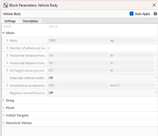
To design a Vehicle Body we are using the simscape library and the following blocks are used to simulate the vehicle body
- vehicle body
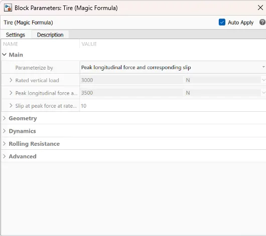
- Tire (magic formula)
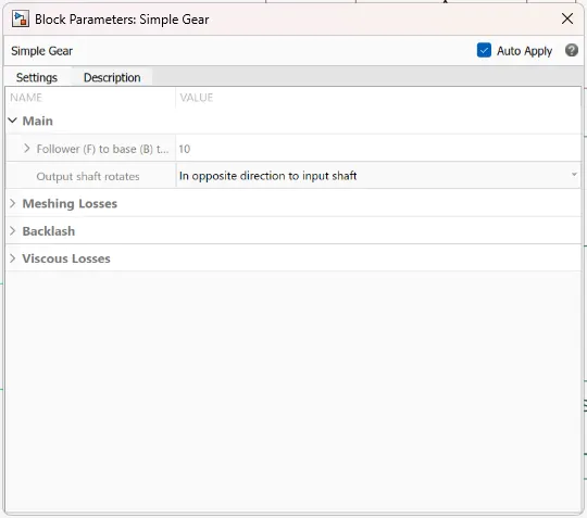
- simple Gear
- Ideal Translational Motion Sensor
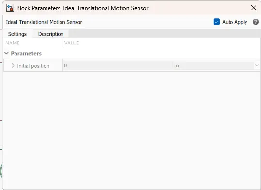
by this blocks let us connect and form an vehical body in SIMULINK
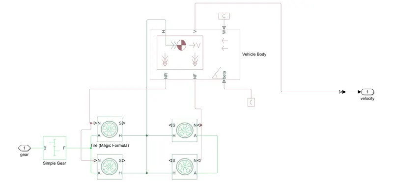
Four wheels are connected in two axles mode as the vehicle is an rear wheel drive the gear is connected to the rear wheel combo the simple gear is powered by motor which is designed later the vehicle body is connected to the wheels as shown in the figure the wind and beta which is inclination angle is assumed to be zero the velocity of the vehicle is fed back to the longitudanal driver for the velocity feedback. An Ideal transslational motion sensor is connected to the hub where as it gives the velocity of the vehicle and ditance covered by the vehicle.
now let us design the Motor and its controller.
Motor and its controller:
PM BLDC motor: Among various types of motor drives, permanent magnet (PM) brushless motor drives, especially the PM BLDC motor drive, are currently the most attractive motor drives for electric vehicle (EV) propulsion. Their key features, namely high power density and high efficiency, are attributed to the use of high-energy PM material. Actually, they are becoming dominant in the market share of EV motor drives. However, these PM brushless motor drives still have some shortcomings such as high cost and thermal
instability of the PM material. The key is to use electronic commutation to replace the mechanical commutation. Hence, the most obvious advantage of the PM BLDC machine is the removal of commutator and brushes, leading to eliminate many problems associated with them. The PMBLDCmachine has a similar structure as the PMsynchronous machine, namely the three-phase stator windings and PM rotor. However, the PM BLDC machine generally adopts the concentrated winding instead of the distributed winding, and has the trapezoidal air-gap flux density distribution instead of the sinusoidal flux distribution. Because of the use of concentrated windings, the end-windings can be significantly shortened, hence saving the copper material and associated copper loss. In general, the PM BLDC machine adopts the surface-mounted PM rotor as depicted in Figure, which takes the definite advantages of simplicity in both structure and control. Nevertheless, other types of PM rotors such as the surface-inset, interior-radial, and interior-circumferential topologies can also be adopted, provided the air-gap flux density distribution is close to trapezoidal; otherwise, the torque production will be deteriorated.
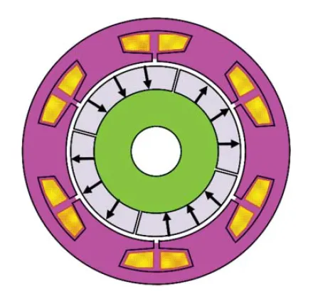
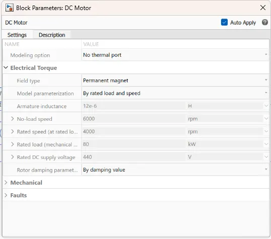
Designing a motor includes so many parameters but we have the Power required to generate by the motor and aalso its torque to overcome the forces acting on a vehicle
so the rated output power is 80kW
rated RPm at no load is set to 6000 and at full load set to 4000 RPM
for designing the motor and its controller we are using the following blocks from simscape library
- BLDC motor
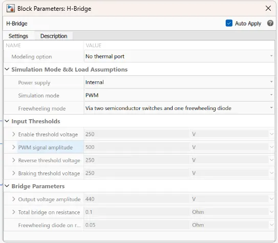
- H-bridge Converter
A H-bridge is an electronic circuit that switches the polarity of a voltage applied to a load. These circuits are often used in robotics and other applications to allow DC motors to run forwards or backwards. The name is derived from its common schematic diagram representation, with four switching elements configured as the branches of a letter "H" and the load connected as the cross-bar.
- Controlled PWM Voltage
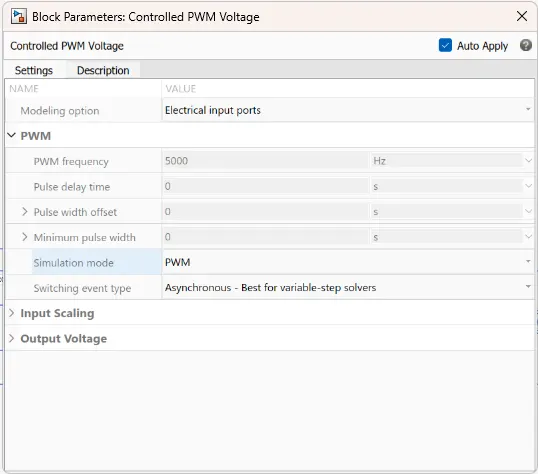
- Controlled Voltage source
- current measeurement
- simulink to ps converter
let us connect each block for motor and converter using SIMULINK
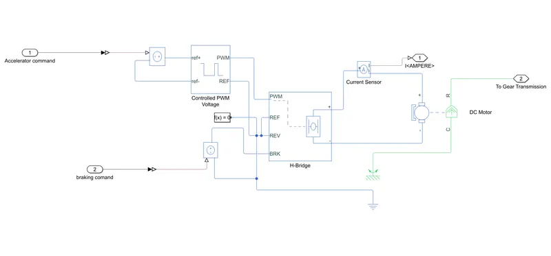
the accelearation and deceleration commands from the longitudanal driver block is fed to the controlled voltage source blocks, the accl controlled source block is fed to the controlled pwm block to give the desired waveform to the H bridge converter as well as the deceleration command is fed to the brk of the h bridge converter. the h bridge convereter feeds the dc motor the current is measured and fed to the battery pack as vell as the drive shaft is connected to the vehicle body later.
Now let us simulate the Battery pack.
Battery Pack:
The sodium-ion battery (NIB or SIB) is a type of rechargeable battery analogous to the lithium-ion battery but using sodium ions (Na+) as the charge carriers. Its working principle and cell construction are almost identical with those of commercially widespread lithium-ion battery types, but sodium compounds are used instead of lithium compounds.
Sodium-ion batteries have received much academic and commercial interest in the 2010s and 2020s as a possible complementary technology to lithium-ion batteries, largely due to the uneven geographic distribution, high environmental impact and high cost of many of the elements required for lithium-ion batteries. Chief among these are lithium, cobalt, copper and nickel, which are not strictly required for many types of sodium-ion batteries. The largest advantage of sodium-ion batteries is the high natural abundance of sodium. This would make commercial production of sodium-ion batteries less costly than lithium-ion batteries.
The Battery Pack is designed to give the soc and current values of the battery which gets the current feedback from the Dc motor drive
the soc is calculated as follows
`soc%=I/(146Ahxx3600)`
let us see the simulink model to understand further
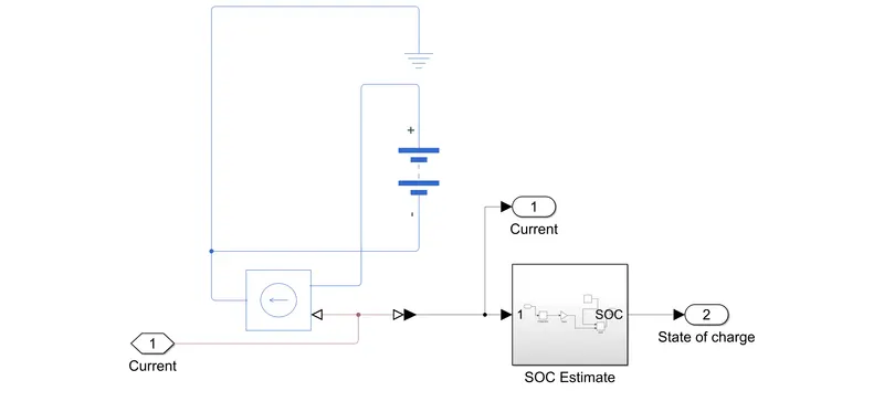
The Current feed back from the DC motor Drive converter to the controlled current source to feed the battery as well as the soc percentage is calculated as stated above
the battery current and soc% is scoped.
now let us design the longitudanaal driver and drive cycle
Driver And Drive Cycle:
The Longitudanal driver block and a drive cycle block from powertrain blockset library is used.
FTP45 drive cycle is selected
The EPA Federal Test Procedure, commonly known as FTP-75 for the city driving cycle, are a series of tests defined by the US Environmental Protection Agency (EPA) to measure tailpipe emissions and fuel economy of passenger cars (excluding light trucks and heavy-duty vehicles).
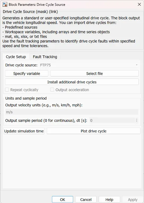
the drive cycle feeds the longitudanal drivers velocity reference
Simulation Diagram:
Now let us see the whole simulation model to understaand the model more further
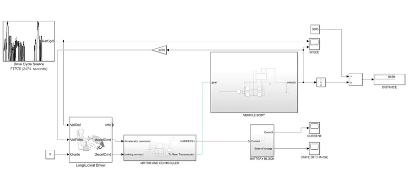
the drive cycle with reference of FTP75 cycle and uses 2474 seconds of the simulation time is fed to the velref port of the longitudanal driver block, a velocity feedback from the vehicle body is fed to the velfdbk port of the longitudanal driver block, grade is assumed as zero with a contant block, accel cmd and decclcmd ports are fed to the motor with controller which are reference to the controlled voltage sourec blocks as explained in the motor with controller segment, the current feed back is fed to battery pack to give desired current rating and the soc. motor is coupled with vehicle body as shown in the figure.
Results:
Now let us simulate the design to know the vehicle speed with respect to the time
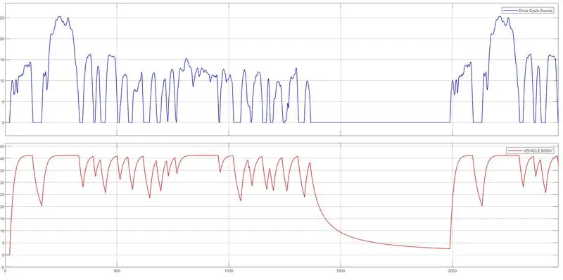
due to the improved feed back of velocity we can see the better velocity response from the vehicle
let us see the battery current and soc%
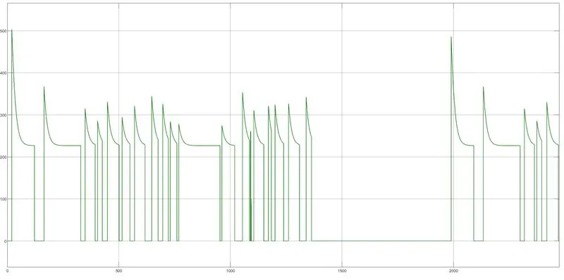
we can observe that the current is utilized whenever the vehicle is accelerating and we see drops at deceleration as well
let us see the soc% of battery
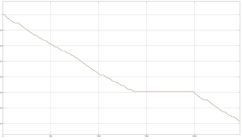
we can observe that the 100% charge came to 30%charge
Conclusion: The system level Configaration, model parameters and results are explained. By the Obtained values an Electric Car is simulated with battery and DC motor by giving velocity reference as FTP75 drive cycle, during the whole cycle the vehicle maintained 40kmph max speed and used 70% of battery the vehicle feed back velocity improves vehicle performance by increasing the power of the motor and battery capacity. The Total distance covered by the vehicle is 19.69kms.
Links: https://drive.google.com/file/d/1-500bj16pWGaQMYJt4tQkVVmFhTlfqt5/view?usp=drivesdk