Final Project: Design of an Electric Vehicle
Create a MATLAB model of electric car which uses a battery and a DC motor. Choose suitable blocks from Powertrain block set. Prepare a report about your model including following:
Objectives:
1. System level configurations
2. Model parameters
3. Results
4. Conclusion
Electric Vehicle:-
An electric vehicle (EV) is a vehicle that uses one or more electric motors for propulsion. It can be powered by a collector system, with electricity from extravehicular sources, or it can be powered autonomously by a battery (sometimes charged by solar panels, or by converting fuel to electricity using fuel cells or a generator). EVs include, but are not limited to, road and rail vehicles, surface and underwater vessels, electric aircraft and electric spacecraft.
Electric vehicles have low running costs as they have less moving parts for maintaining and also very environmentally friendly as they use little or no fossil fuels (petrol or diesel). While some EVs used lead acid or nickel metal hydride batteries, the standard for modern battery electric vehicles is now considered to be lithium ion batteries as they have a greater longevity and are excellent at retaining energy, with a self discharge rate of just 5% per month. Despite this improved efficiency, there are still challenges with these batteries as they can experience thermal runaway, which have, for example, caused fires or explosions in the Tesla model S, although efforts have been made to improve the safety of these batteries.
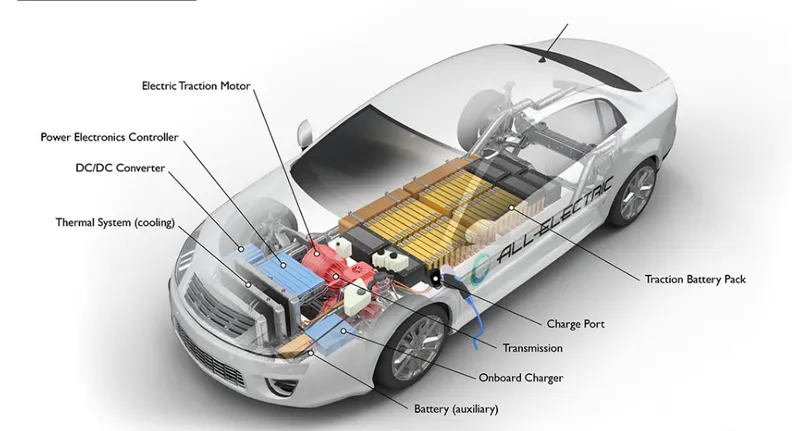
The Main Componants Of the Electric Vehicles Are Following:-
- Traction battery pack
- DC-DC Converter
- Electric motor
- Power inverter
- Charge Port
- Onboard charger
- Controller
- Thermal system (cooling)
- Transmission.
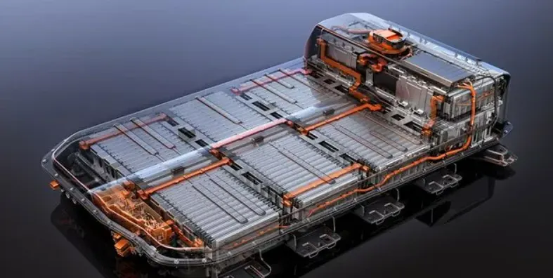
1. Traction battery pack:-
Traction battery pack is also known as Electric vehicle battery (EVB) . It powers the electric motors of an electric vehicle. The battery acts as an electrical storage system. It stores energy in the form DC current. The range will be higher with increasing kW of the battery. The life and operation of the battery depends on its design. The lifetime of a traction battery pack is estimated to be 200,000 miles.
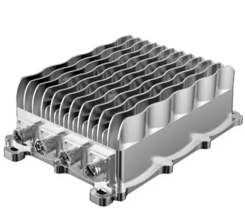
2. DC-DC convertor
The traction battery pack delivers a constant voltage. But different components of the vehicle has different requirements. The DC-DC convertor distributes the output power that is coming from the battery to a required level. It also provides the voltage required to charge the auxiliary battery.
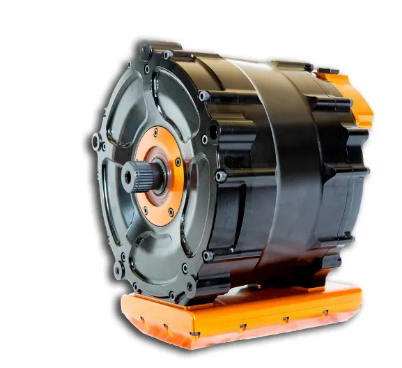
3. Electric motor.
Electric traction motor is the main component of an electric vehicle. The motor converts the electrical energy into kinetic energy. This energy rotates the wheels. Electric motor is the main component that differentiates an electric car from conventional cars. An important feature of an electric motor is the regenerative braking mechanism. This mechanism slows down the vehicle by converting its kinetic energy into another form, and storing it for future use. There are basically two types of motors DC and AC motors.
4. Power Inverter.
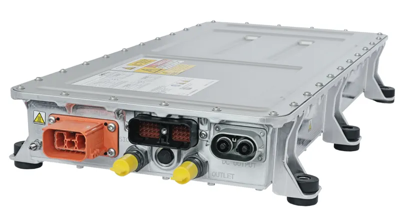
It coverts DC power from the batteries to AC power. It also converts the AC current generated during regenerative braking into DC current. This is further used to recharge the batteries. The inverter can change the speed of the Motor.
5. charging port.
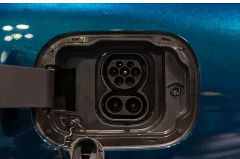
The charge port connects the electric vehicle to an external supply. It charges the battery pack. The charge port is sometimes located in the front or rear part of the vehicle.
6. Onboard charger.
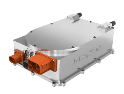
Onboard charger is used to convert the AC supply received from the charge port to DC supply. The on-board charger is located and installed inside the car. It monitors various battery characteristics and controls the current flowing inside the battery pack.
7. controller
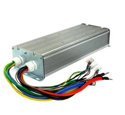
Power electronics controller determines the working of an electric car. It performs the regulation of electrical energy from the batteries to the electric motors. The pedal set by the driver determines the speed of the car and frequency of variation of voltage that is input to the motor. It also controls the torque produced.
8. Tharmal System Cooling.
The thermal management system is responsible for maintaining an operating temperature for the main components of an electric vehicle such as, electric motor, controller etc. It functions during charging as well to obtain maximum performance. It uses a combination of thermoelectric cooling, forced air cooling, and liquid cooling.
9.Transmission.
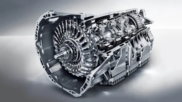
It is used to transfer the mechanical power from the electric motor to the wheels, through a gearbox. The advantage of electric cars is that they do not require multi-speed transmissions. The transmission efficiency should be high to avoid power loss.
Link:- https://www.twi-global.com/technical-knowledge/faqs/what-is-an-ev
Link:- https://yocharge.com/in/ev/components/
Block Digram Off The Electric Vehicle.
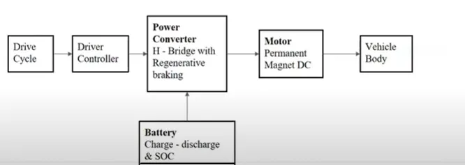
DETAIL STUDY OF THE VEHICLE BODY SUBSYSTEM.
Objectives To create the Electric Vehicle In matlab.
- To Make the Most Simple And Low run Time vehicle model using individual componant model.
- To check the out performance:speed,SOC,current etc with Drive cycle.
- To understand The motor power,vehicle body,(Rolling Resistance,Air Drag, Weight)inputs.
- To know Matlab Models and their configuration to matcyh with actual vehicle.
Main Subsystem of the Electric-vehicle.
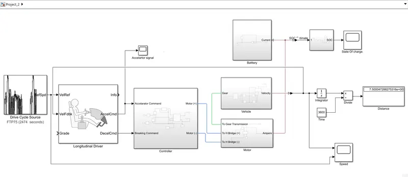
For modelling the whole vehicle in SIMULINK. we need to model the above emntioned components separately and make them work together.
All the main components are available in the library of SIMULINK blocks.
so we add components and configure the parameters to fit the the working requirements of the model.
In This We Implement the Five SubSystems.
- Vehicle.
- Motor.
- Controller.
- Battry.
- State Of Charge.(SOC)
- Longitudinal Drive Block.
- Drive Cycle.
1.Sub-system Of the Vehicle.
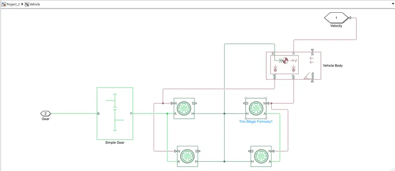
In This Subsystem Consist Of Following Componants Or Parts:-
1. Tire:-
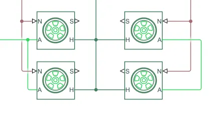
- H is noting but HUB.
- A is nothing but the axel.
- N is the normal force.
- S stands for slip.
- We selected The Four Tire For Four Wheeler we consider Left of the tire as a rear tire and N Port of the tire conected to NR port of the vehicle body.
- And we consider Right of the tire as a front tire and N Port of the tire conected to NF port of the vehicle body.
- H port of the Tire is conected to the H port of the vehicle body.
- Left of the Axel Port (A) is going to the motor.
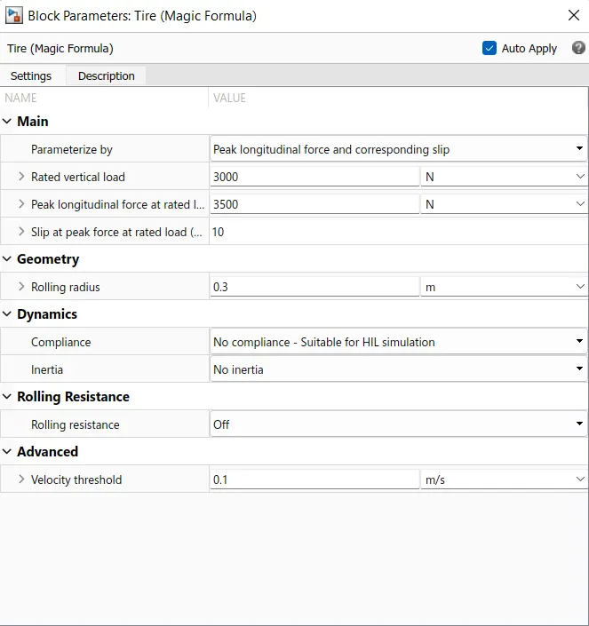
Parameters Of The Block.
2. Vehicle Body :-
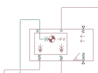
- Represents a two-axle vehicle body in longitudinal motion. The block accounts for body mass, aerodynamic drag, road incline, and weight distribution between axles due to acceleration and road profile.
- The vehicle can have the same or a different number of wheels on each axle. Optionally include pitch and suspension dynamics or additional variable mass and inertia.
- The vehicle does not move vertically relative to the ground.
Connection H is the mechanical translational conserving port associated with the horizontal motion of the vehicle body. The resulting traction motion developed by tires should be connected to this port. - Connections V, NF, and NR are physical signal output ports for vehicle velocity and front and rear normal wheel forces, respectively. Wheel forces are considered positive if acting downwards.
- Connections W and beta are physical signal input ports corresponding to headwind speed and road inclination angle, respectively.
- If variable mass is modeled, the physical signal input ports CG and M are exposed. CG accepts a two- element vector representing the x and y distance offsets from vehicle CG to additional load mass CG.
- M represents the additional mass. If both variable mass and pitch dynamics are included, the physical signal port J accepts the inertia of the additional mass about its own CG.
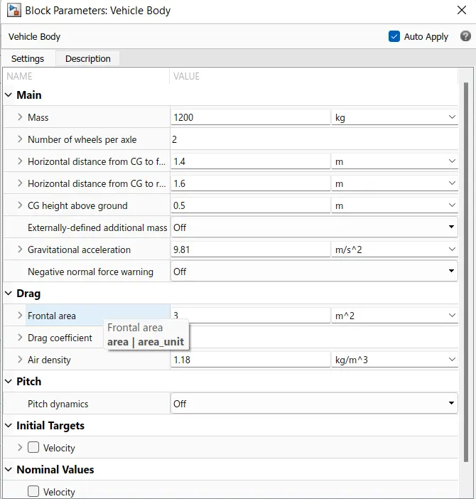
Parameters Of The Block.
3. Gear System.
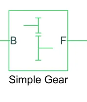
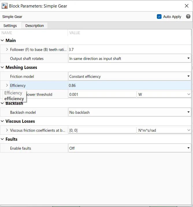
- Represents a fixed-ratio gear or gear box. No inertia or compliance is modeled in this block. You can optionally include gear meshing, backlash, and viscous bearing losses.
- Connections B (base) and F (follower) are mechanical rotational conserving ports. Specify the relation between base and follower rotation directions with the Output shaft rotates parameter.
- Optionally include thermal effects and expose thermal conserving port H by setting Friction model to a temperature-dependent setting.
Parameters Of The Block.
2. Sub-system Of the Motor.
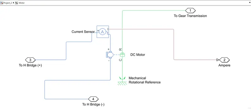
In This Subsystem Consist Of Following Componants Or Parts:-
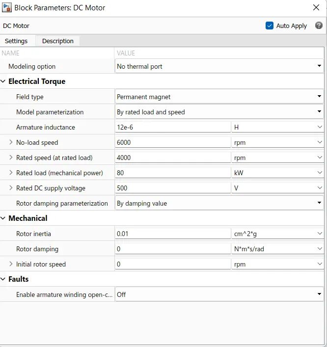
1. DC Motor:-
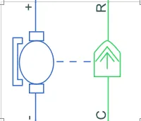
- For EV model we selected the DC motor block Which Is Brush Type DC Motor And implementation is simle compare to others and its have few parameters.
- In This motor Block two sides which is Right one is mechanical side and Left is electrical side.
- In mechanical side has a two ports C And R. C is the nothing but the casing and it is standstill And R is nothing But the Rotor Which is produced the toque.
- In electrical side Two Ports Which Possitive and anather is Negative for voltage is applied. the possitive port is going to the possitive side of the H-bridge through the current sensor block and negative is connected to the Negative side of the H-Bridge.
- Mechanical side R port is connected to the gear in the vehicle body block And C port is connected to the Rotational Reference Block because the its stationary.
Parameters Of The Block.
2. Current Sensor :-
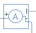
- This device that converts current measured in any electrical branch into a physical signal proportional to the current.
- In this Two Port + and - are conserving electrical ports through which the sensor is inserted into the circuit. Connection I is a physical signal port that outputs current value.
3. Mechanical Rotational Refrance :-

This block represents a mechanical rotational reference point, that is, a frame or a ground. Use it to connect mechanical rotational ports that are rigidly affixed to the frame (ground).
3. Sub-system Of the Controller.
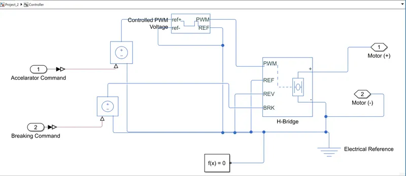
In This Subsystem Consist Of Following Componants Or Parts:-
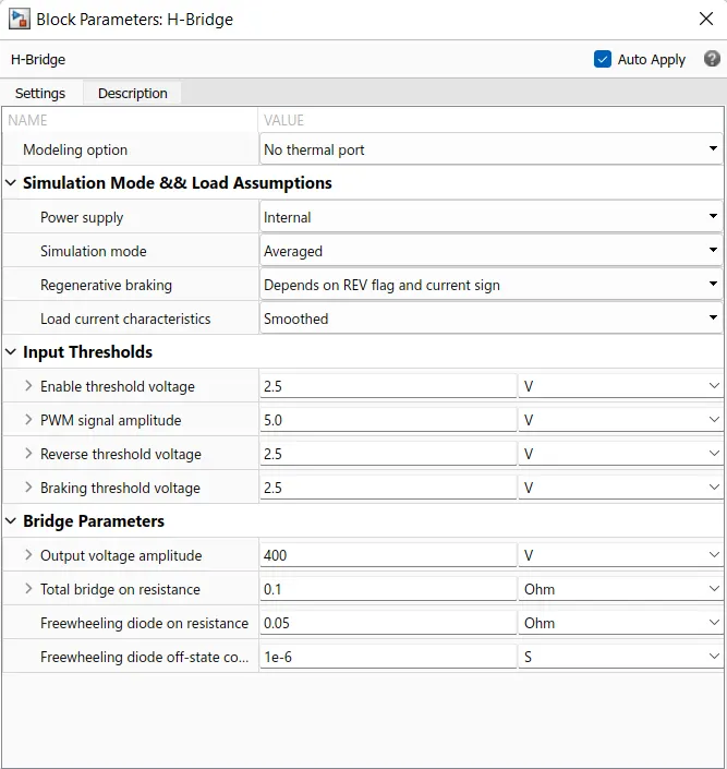
1. H-Bridge:-
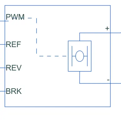
- This is a power converter which is needed to provide power of the correct form and magnitude from one component to other.
- In case of EV,s a power converter is needed to provide a DC voltage from the battery of the EV to the DC motor, so that it can fuction properly at the required parameters.
- Here i have used an H-bridge motor drive as my power converter.
- The left side is for controlling the voltage signalsand the right side terminals to provide the controlled voltage to the DC motor the left side ports are:
- PWM- Pulse width modulation
- REF- Reference
- REV- Reverse
- BRL- Brake
Parameters Of The Block.
2. Controlled PWM Voltage Block.
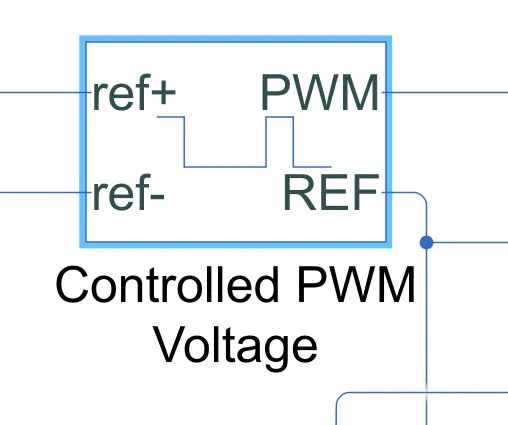
- This block creates a Pulse-Width Modulated (PWM) voltage across the PWM and REF ports.
- The output voltage is zero when the pulse is low, and is equal to the Output voltage amplitude parameter when high.
- Duty cycle is set by the input value.
- At time zero, the pulse is initialized as high unless the duty cycle is set to zero or the Pulse delay time is greater than zero.
- The Simulation mode can be set to PWM or Averaged. In PWM mode, the output is a PWM signal. In Averaged mode, the output is constant with value equal to the averaged PWM signal.
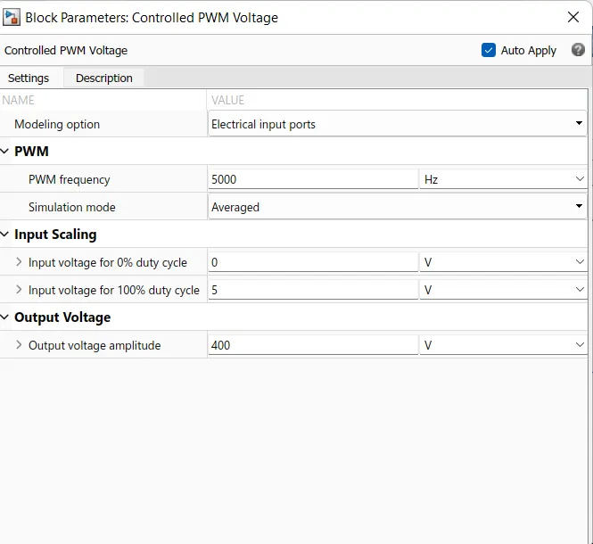
Parameters Of The Block.
3. Controlled Voltage Source.
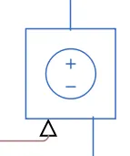
- The block represents an ideal voltage source that is powerful enough to maintain the specified voltage at its output regardless of the current passing through it.
- The output voltage is V = Vs, where Vs is the numerical value presented at the physical signal port.
4. Solver Configuration.
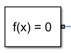
Defines solver settings to use for simulation.
Parameters Of This Block is set as defult .
5. Electrical reference.
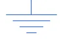
Electrical reference port. A model must contain at least one electrical reference port (electrical ground).
4. Sub-system Of the Battery.
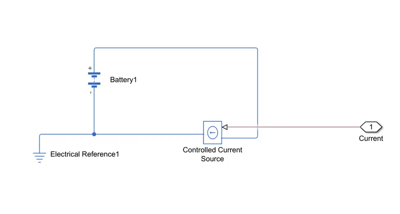
In This Subsystem Consist Of Following Componants Or Parts:-
1. Battery.

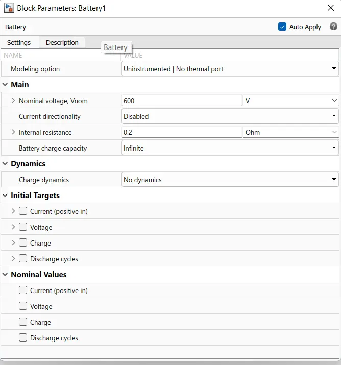
- We Select the Lithium-Ion battery type.
- Norminal Voltage is 600 V for our condition and Internal Resistance is 0.2 ohm.
Parameters Of The Block.
2. Controlled Current Source.

- The block represents an ideal current source that is powerful enough to maintain the specified current through it regardless of the voltage across it.
- The output current is I = Is, where Is is the numerical value presented at the physical signal port.
3. Electrical Refrance.
Electrical reference port. A model must contain at least one electrical reference port (electrical ground).
5. Sub-system State Of Charge(SOC).
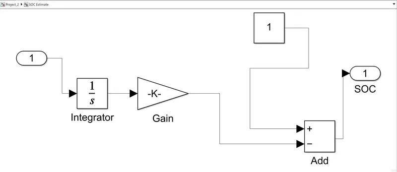
- To measure the state of charge of the battery, a sub-system was created of various blocks.
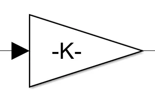
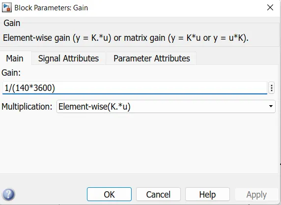
- The first block is integrator block used to handle data transfer and integrate the value of the current signal with respect to time and next is the Gain block is used in order to multiplyer divide the signal coming from integrator block.
- This block will divide the current signal with the ampere ratingof battery which is 140(Ah)*3600(secs in hour) .
- Assuming the battery is always fully charged I have added the constant block with a value of 1 representing 100%.
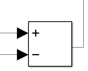
- Next a sum block is used to perform addition and substraction operations athese blocks aremade into a subsystem called SOC estimate.
- A scope block is used at the junction of the PS-simulink converter block to plot the output signall of the current from the battery.
In This Subsystem Consist Of Following Componants Or Parts:-
1. Integrator.
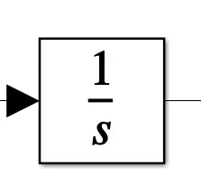
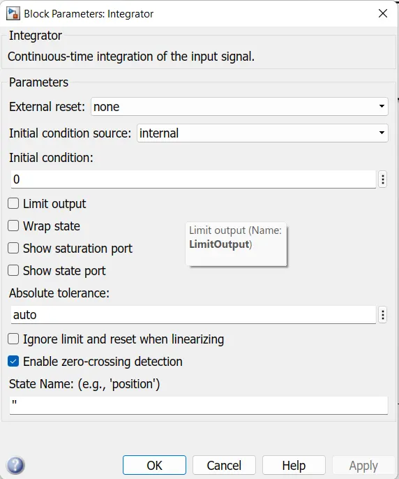
Continuous-time integration of the input signal.
Parameters Of The Block.
2. Gain.
Parameters Of The Block.
3. Addition Block.
- A parametric longitudinal speed tracking controller for generating normalized acceleration and braking commands based on reference and feedback velocities.
- Use the external actions to input signals that can disable, hold, or override the closed-loop commands determined by the block. The block uses this priority for the input commands: disable, hold, override.
6. Longitudinal Driver Block.
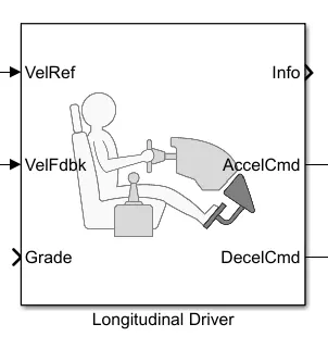
The longitudinal driver block is used for giving normalized acceleration and deacceleration commants to a controller based on two sets of data. The first data is the reference velocity and second data is the feedback velocity.The reference velocity data coming from drive cycle source and is compared to the feedback velocity data coming from the vehicle body. If the reference velocity is greater than the feedback velocity, an acceleration comand will be given as an output to the controlled voltage source. If the reference velocity is lesser than the feedback velocity, a deacceleration command is given as output to anpother controll voltage source. For the output acceleration and deacceleration commands i have used simulink-PS converter block. In this case the input signal; is velocity data and this is logic data which have to be converted to a voltage signal The ports in this block are:
- Velref- This stands for the reference velocity and it is the velocity data provided from a drive cycle source.
- Velfdbl- This stands for feedback velocity and it is coming from the vehicle's body velocity port
- Grade- This port provides a grade or inclination angle on which the vehicle is travelling in degrees.
- Info- This port is for the bus signals which consists of block calculations
- Accelcmd- This port provides the acceleration command to a controlled voltage source
- Deacclcmd- This port provides the deacceleration command to another voltage source.
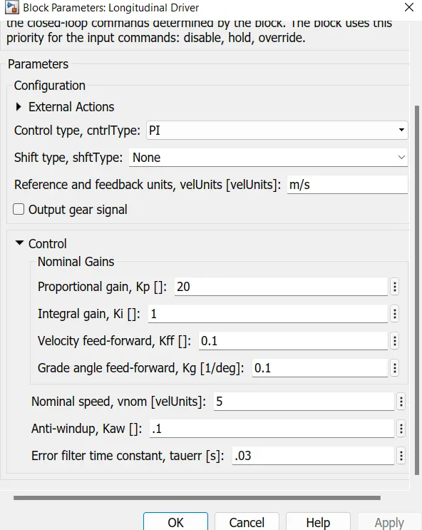
Parameters Of The Block.
7. Drive cycle.
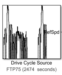
We Select The FTP75 Drive Cycle
A drive cycle is a data set that contains velocity and time data for the purpose of modelling the motion of a vehicle. It is a plot of the vehicle velocity against the time and it is made to resembl typicall driving conditions that a consumer may experience themselves in. Drive cycles are used by various testing procedures such as mileage, pollution tests, and acceleration and top speed tests.There are three ways of implementing a drive cycle. One method is to create your own drive cycle with spreedsheet or excelsheet. Another method isuse a signal builder and create siganls according to the user and the method that we used is to implement industry standard drive cycles which are previosly used to test parameters of the vehicle.
Parameters Of The Block.
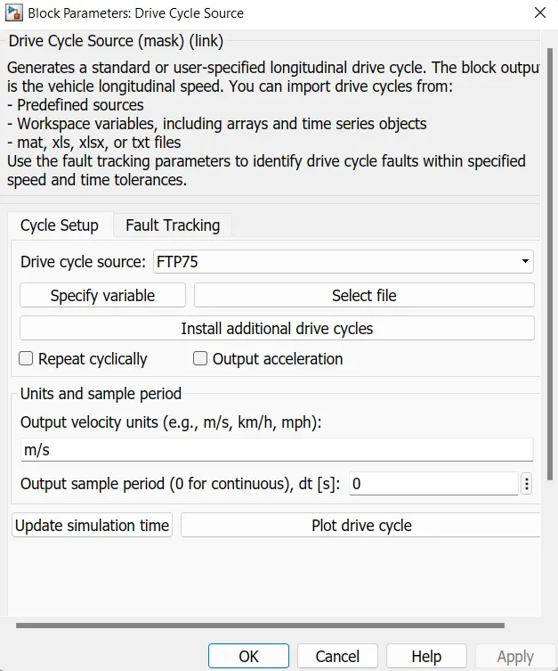
We Run the above drive cycle for We implimentd EV model and Take the outputs. The distance travelled by the vehicle in the drive cycle is also measured using the display block. Before simulation the run time was updated according to the drive cycle time 2474secs.
Scope Outputs As following.
- Speed
- State Of charge (SOC).
- Accelarator Signal.
1 .Speed Output.
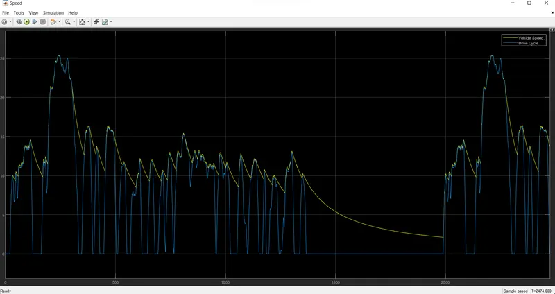
- From this scope we can see two signals. The Blue Colour signal Shows the Drive Cycle Data and yellow Signal show the Implimented EV module which similer to Drive cycle Signal.
- As we can see that the longitudinal driver successfully maintains the drive cycle data , process it and controls the vehicle's speed according to the reference speed.
- the graph overlaps eachother effectively during acceleration and deacceleration.
2 .State Of Charge(SOC).
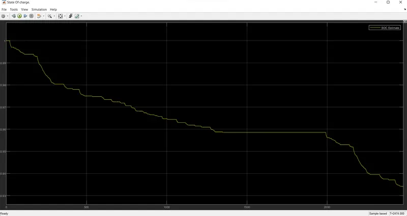
The SOC scope shows how the state of the battery varies over the drive cycle time, The batter was modelled to begin with an SOC pf 1 that is 100%. As the simulation starts the charge of the bettery gets decreased and when the vehicle is in braking mode the uplift in the grapf shows that regenerative braking is working to maintain the battery charge.
3. Accelarator Signal.
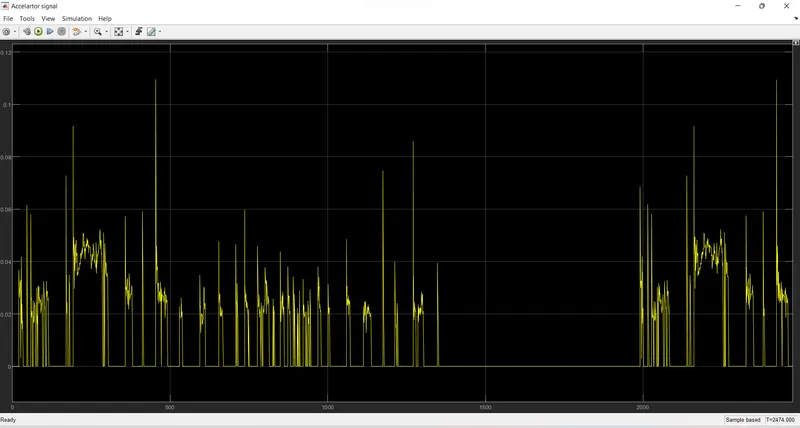
This Scope Shows the Accelarator Signal oF the refrance drive cycle Data.
Distance:-
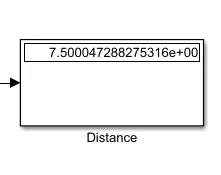
From the above image the display block measured the distance which is 7.50kms in 2474secs.
Conclusion:-
We Implement The Ev Module In imulink With DriveCycle FTP75 and we Observed The speed, Distance Battery State of Chrage(SOC). From the model we have achieved the distance of almost 7.50 kM. The EV model was able to follow the commands given by reference velocities from the drive cycle data.
we can say that the vehicle is efficient.
Zip File :- https://drive.google.com/file/d/1-G5COGMXwEA8dJLjHH7_uTSJEmxMSoXI/view?usp=sharing