Final Project: Design of an Electric Vehicle
Create a MATLAB model of electric car which uses a battery and a DC motor. Choose suitable blocks from Powertrain block set. Prepare a report about your model including following:
Objectives:
1. System level configurations
2. Model parameters
3. Results
4. Conclusion
Answer: -
Obejctives of Project: -
- Design and simulate the electric vehicle in Matlab and simulink using required blocks.
Introduction to EV
Electric vehicles are either partially or fully electric. EVs are becoming increasingly popular because they have low running costs and are environmentally friendly. EVs have electric motors that power the vehicle. These electric motors are powered by lithium-ion batteries, which are excellent at retaining energy and have greater longevity than other variants.
Different Types of EVs
There are two main types of electric vehicles: Battery (BEV) and Plug-in Hybrid (PHEV).
Battery Electric Vehicle (BEV)
A BEV is an electric vehicle that is powered only by batteries. These batteries need to be recharged regularly, similar to how you would recharge your cell phone or laptop. The main advantage of BEVs is that they have zero emissions, making them very environmentally friendly. BEVs are also very efficient and have low running costs.
Plug-in Hybrid Electric Vehicle (PHEV)
A PHEV is an electric vehicle powered by both batteries and gasoline. PHEVs have electric motors that are powered by batteries that you can recharge by plugging the vehicle into a suitable charging point. PHEVs also have a gasoline engine that can be used to power the vehicle. The main advantage of PHEVs is that the gasoline variant serves as emergency energy that you can use if you run out of power on the road. Like BEVs, PHEVs also have low running costs.
The battery in a PHEV is much smaller, making them lighter and more efficient to use. Usually, the electric engine can power the vehicle between 10 to 50 miles. Once the electric power runs out, the gasoline engine will take over and power the vehicle.
Owning an EV comes with many perks that benefit you and the environment. With that said, here are some notable benefits of owning an EV:
Environment-friendly Vehicle
As we mentioned earlier, EVs are environmentally friendly because they produce zero emissions, which means they don’t contribute to air pollution. Electricity is also a clean energy source, so electric vehicles don’t produce the harmful greenhouse gasses that gasoline-powered vehicles do.
Lower Maintenance Costs
EVs have electric motors instead of gasoline engines. Electric motors have fewer moving parts than gasoline engines, requiring less maintenance. This can lead to lower long-term ownership costs.
Incentives and Tax Credits
Owning an EV may entitle you to certain incentives and tax credits. For example, the US federal government offers a tax credit of up to $7500 for EVs. Some states also offer additional incentives, such as rebates or free parking. To check what incentives are available in your area, be sure to check with your local government.
Better Driving Experience
Finally, a lesser-known benefit of EVs is that they actually provide a better driving experience. EVs have instant torque to help them accelerate quickly. This makes EVs great for city driving. EVs are also very quiet so that you can enjoy a peaceful ride.
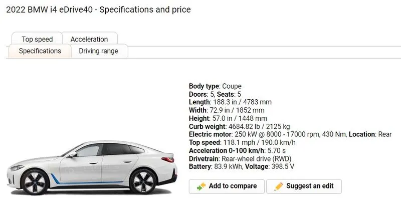
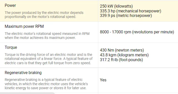
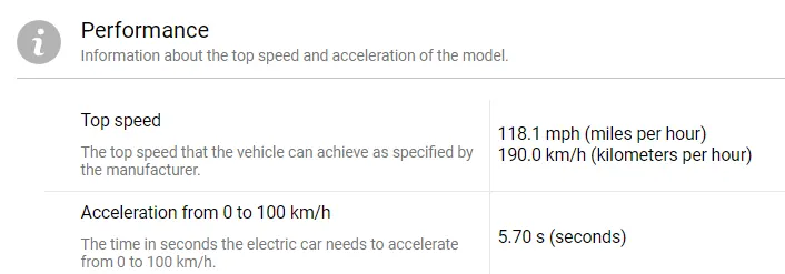
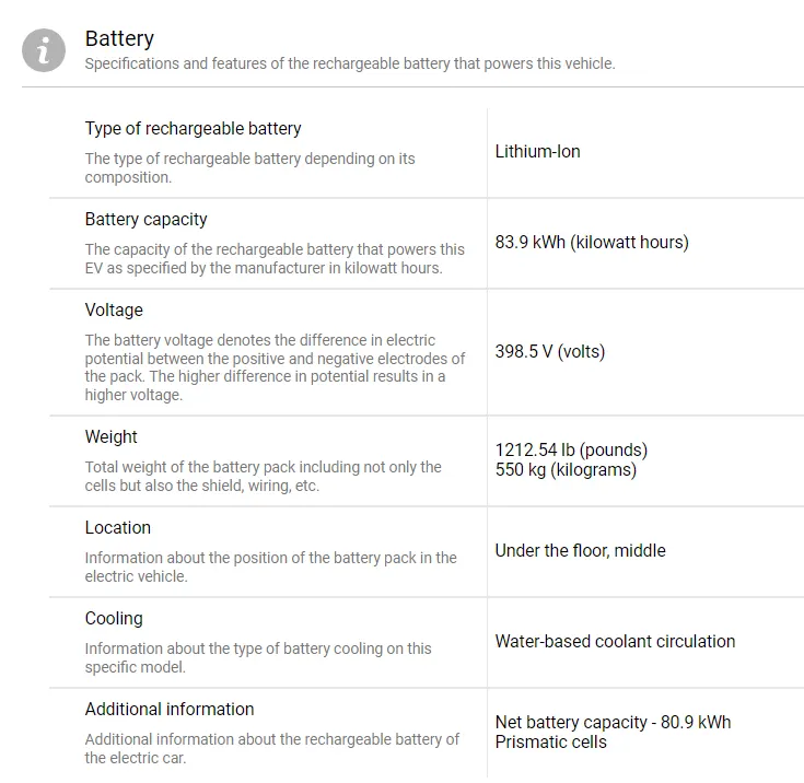
This project presents a MATLAB/SIMULINK model of an entire electric vehicle (EV). I have decided to model the 2022 BMW I4 e DRIVE 40 and simulate its characteristics for this project. Maximum parameters of vehicle is available at online and which are not available they are assumed.

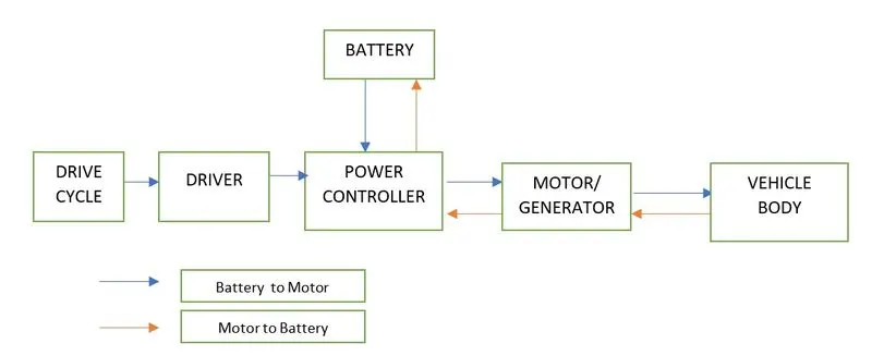
The main components of an EV are:
- Battery
- Drive Cycle and Driver
- Motor controller
- Motor/Generator
- Vehicle body
----------------------------------------------------------------------------------------------------------------------------------------------
From above block we can understand that how EV works. The motor is used to run the vehicle body.Power supply to run the motor is provided by the battery ,as per different application EV can be manufacture and as per that battery and motor specification also change. Motor controller is used to control the motor speed and torque.Regenrative braking also used in above model i.e, as brake applied motor reduceses its speed and produce negative torque and power is generated which fed back to battery to charge.
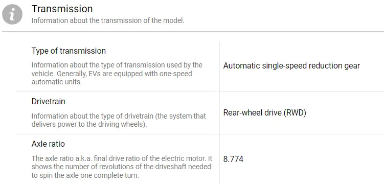
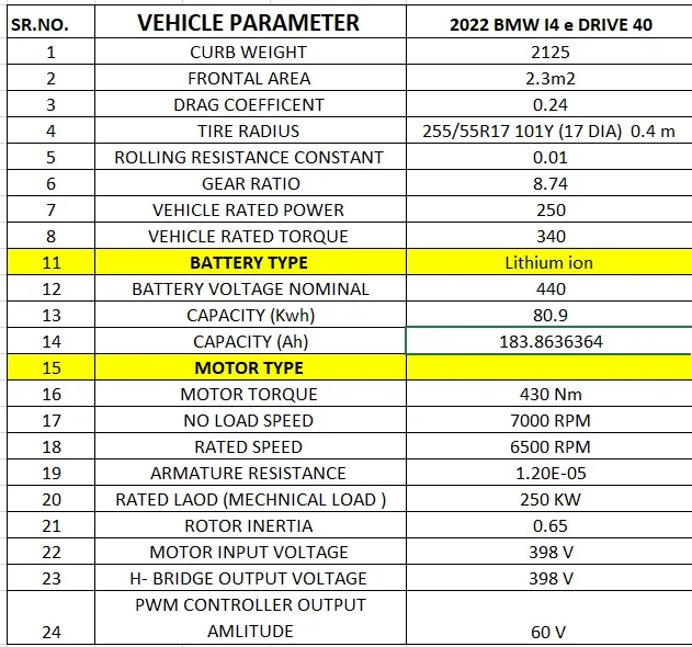
Paramerters used for model are given below in excel sheet
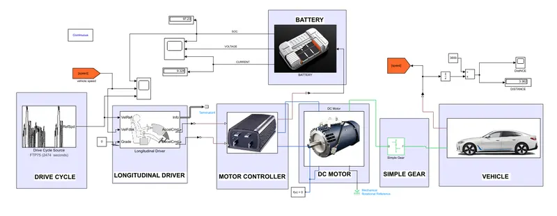
Blocks used and connection:-
- Vehicle Modelling : -
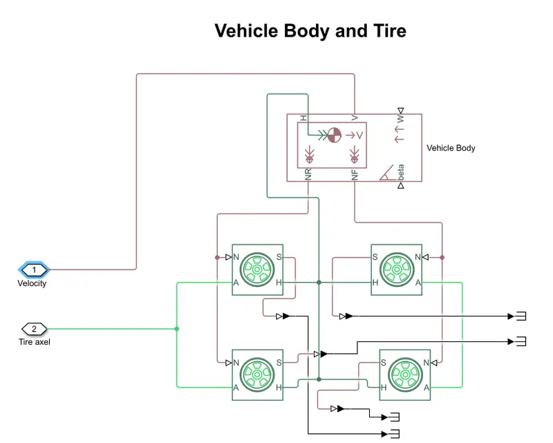
Vehicle modelling consist of Tire and vehicle body.
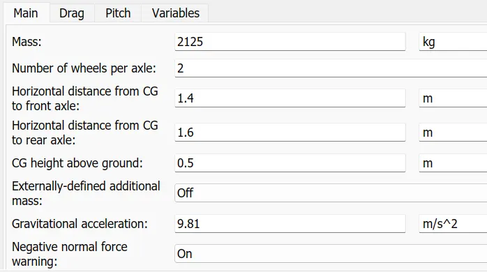
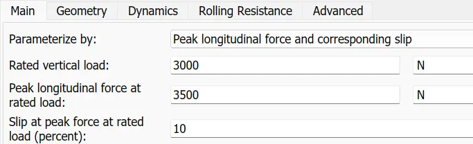
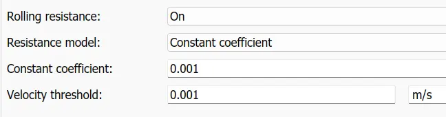
The parameters like vehicle weight, radius of wheels, rolling resistance, drag coefficeint frontal area and gea ratio fot transmission are already mentioned in above table.
4 wheels are used from which two are rear wheel, connected to NR of vehicle body and front wheel are connected to NF of vehicle body block.
Vehicle body Parameters : -

Tire parameters :-


- DC motor : -
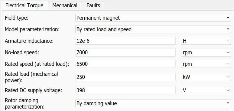
In 2022 BMW I4 e DRIVE 40 permanent magnet synchronous motor is used but for our understanding and simlicity I used DC motor with parameter shown in above table.
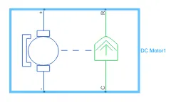
DC motor block consist of + and - block which is connected to powe supply and another terminal like R and C are connected to mechanical blocks. The torque generated by the motor is observe in mechnical movement using R and C port.
R port is connected to Gear which is placed in between vehicle and Motor.
C connected to Mechnical Refreance .
Solver also connect to motor negative port side as solver applies a numerical method to solve the set of ordinary differential equations that represent the model. Through this computation, it determines the time of the next simulation step. In the process of solving this initial value problem, the solver also satisfies the accuracy requirements that you specify.

- Gear :-
Simple gear is used to convert speed of motor for the vehicle application. The gear ratio I used is 8.74 as it mentioned in vehicle parameters.

- Motor Controller: -
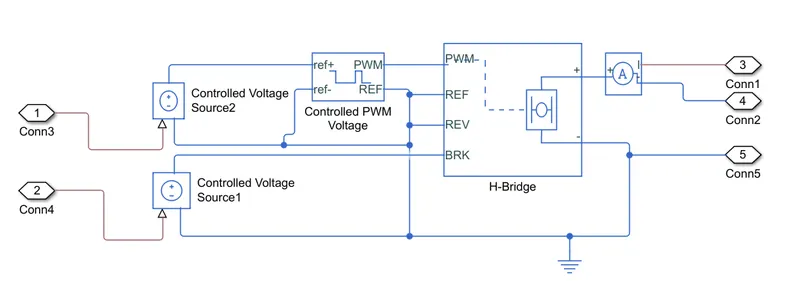
To control the speed of motor Motor controller is required. Motor controller consist of H bridge and Controlled PWM voltage.
Basically motor controller control the voltage input for the motor,hence speed is controlled.
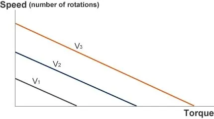
So, what happens to the torque-speed curve when the voltage used to drive the DC motor is changed? The graph below shows the torque-speed curves for different voltages. Doubling the drive voltage doubles both the no-load motor speed and the starting torque (torque when motor is locked in position). In other words, increasing the voltage shifts the torque-speed curve upward, parallelly. The torque-speed curve for a DC motor can be adjusted at will, by changing the voltage applied to the motor.
H bridge : -
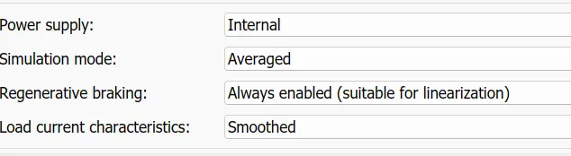
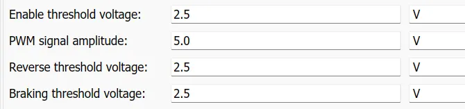
This block represents an H-bridge motor drive. The block can be driven by the Controlled PWM Voltage block in PWM or Averaged mode. In PWM mode, the motor is powered if the PWM port voltage is above the Enable threshold voltage. In Averaged mode, the PWM port voltage divided by the PWM signal amplitude parameter defines the ratio of the on-time to the PWM period.
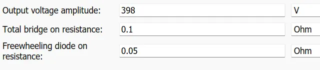
The output voltage of H bridge must be same as motor rating ,in this model motor used required 398 V hence H bridge output is set tov398 V.
We can also used external source for the H bridge,here I used Internal one for easy understanding ,also make simulation mode AVERAGED for fast simulation.As Made Regenerative braking Enabled.
Controlled PWM Voltage :-
This block creates a Pulse-Width Modulated (PWM) voltage across the PWM and REF ports. The output voltage is zero when the pulse is low, and is equal to the Output voltage amplitude parameter when high. Duty cycle is set by the input value.
Controlled output volatge amplitude in higher side as at low voltage amplitude torque and speed genrated by motor is not rated and speed of vehicle and motor does'nt match.
If we take value in very higher side or equal to motor input voltage(398 V) than time taken to simulation get increases.



- Logitudinal Driver and Drive Cycle : -
The Longitudinal Driver block implements a longitudinal speed-tracking controller. Based on reference and feedback velocities, the block generates normalized acceleration and braking commands that can vary from 0 through 1.
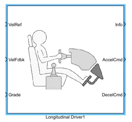
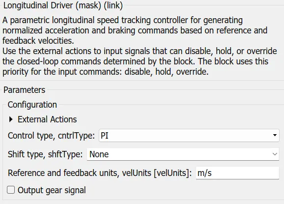
Refrence speed and actual speed of vehicle is fed to block,this block compare both the speed and to equalize them it control accelration and deacceleration command which ultimatly control input voltage to motor.
Controlled voltage sources are connected in between PWM controlled voltage and logitudinal driver block which maintain the specified voltage at its output regardless of the current passing through it.
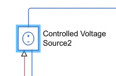
Reference speed is fed to longitudinal driver block using DRIVE CYCLE,
It generates a standard or user-specified longitudinal drive cycle. The block output is the vehicle longitudinal speed.
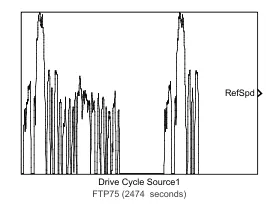
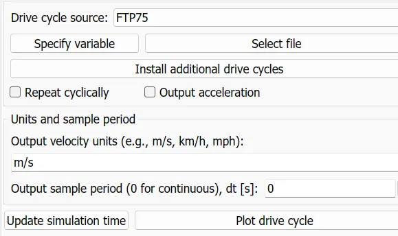
The total duration of drive cycle is 1367 seconds and speed is calculated in m/s.
- Battery
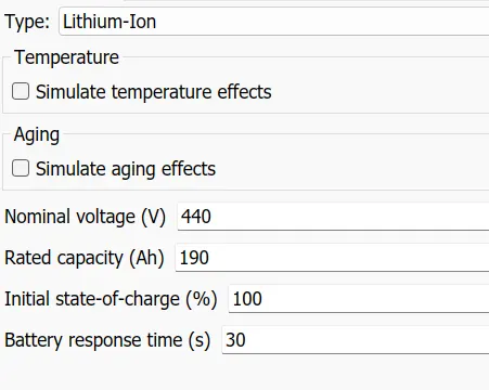
Lithium ion battery is used is used for our model with parameter shown in below.
The output volatge of battery must be slightly greater than motor input voltage.
From battery block we can find values of SOC drop, current taken by load and volatge drop of battery.
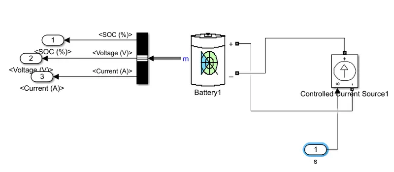
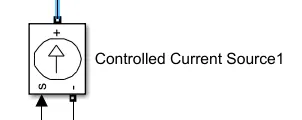
Current controlled source is used to in betweeen battery and motor input .This block is used to convert simulink single to current and this current is controlled by the battery source .
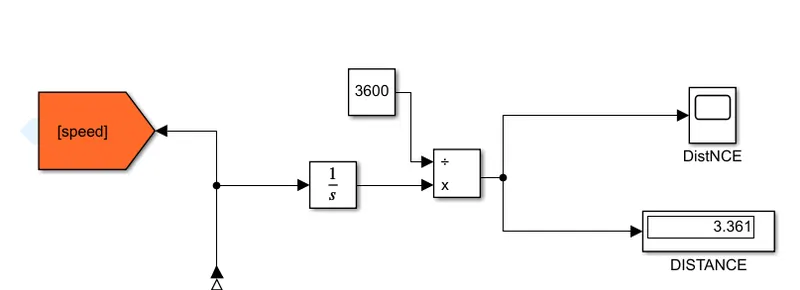
Distance Calculation
Distance = Speed / time
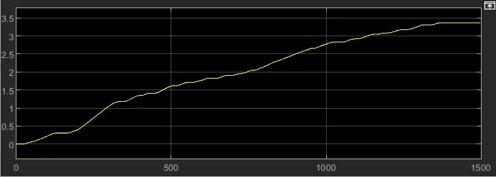
here the speed output of vehicle is in m/sec , we have to convert it into Kmph and then finding distance in Km for that
for that integrate speed value with respect to time we get distance per seconds ,to convert it into hrs divide it by 3600 we get distance in Kmph.
----------------------------------------------------------------------------------------------------------------------------------------
Results
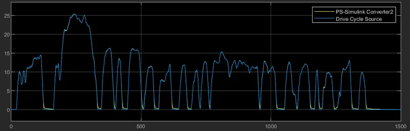
Model run for 1500 seconds.
Drive Cycle refrence wave is yellow one and vahicle speed is blue one as we can able to see that borh speed almost matches.
SOC, Voltage and Current graph
Soc reduces from 100% to 97.23% only to travel distance of 3.362 km.
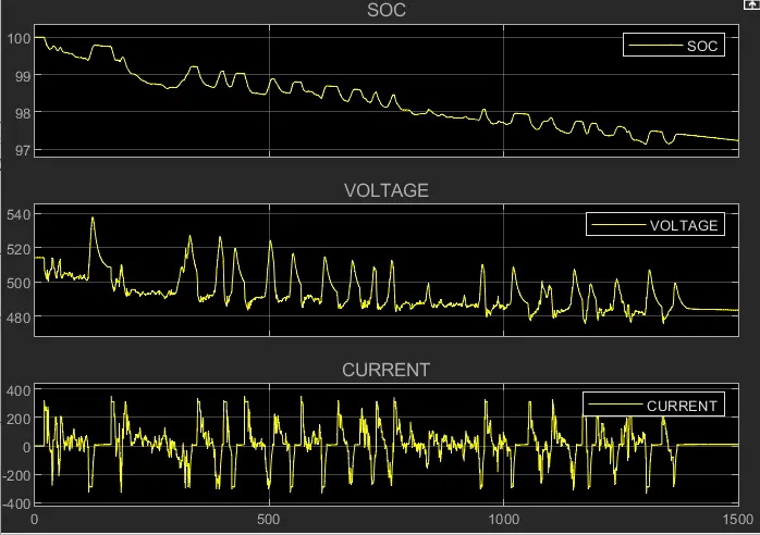
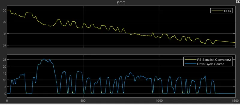
Regenrative braking can be found in graphs that as the brake applied current of battery became negative and SOC start increasing,that means battery is charginf during braking operation.
Distance Travelled is 3.362 Km .
Conclusion: -
- As we take different motor (which is not used in actual model) we got results some what different from the real parameters.
- Regenrative braking can be done using driver block and also battery charging can be done using regenrative braking.
- Speed control of DC motor can be done using Voltage controlled method . Voltage control cn be done using PWM technique and H bridge.
- Using different PI controller also we can controlled Voltage input to motor.
- We can find maximum Km that vehicle can travelled using SOC parameter, at SOC = 0% maximum distance travelled by vehicle.
- Effect of regenrative braking on Battery SOC.
MODEL DRIVE LINK
https://drive.google.com/file/d/1qCs4ll1RJl4Em1CKO9jpnSCaUQY_yoeV/view?usp=sharing
---------------------------------------------------------------------------------------------------------------------------------------------------------------