Final Project: Design of an Electric Vehicle
Create a MATLAB model of electric car which uses a battery and a DC motor. Choose suitable blocks from Powertrain block set. Prepare a report about your model including following:
Objectives:
1. System level configurations
2. Model parameters
3. Results
4. Conclusion
Ans:
Electric vehicle:Environmental as well as economical issues provide a compelling impetus to develop clean, efficient, and sustainable vehicles for urban transportation. Automobiles constitute an integral part of our everyday life, yet the exhaust emissions of conventional internal combustion (IC) engine vehicles are to blame for the major source of urban pollution that causes the greenhouse effect leading to global warming.People dwelling in cities are not exposed to power plant related emissions, because these are mostly located outside urban areas. Electric vehicles (EV) enabled by high-efficiency electric motors and controllers and powered by alternative energy sources provide the means for a clean, efficient, and environmentally friendly urban transportation system. Electric vehicles have no emission, having the potential to curb the pollution problem in an efficient way. Consequently, EVs are the only zeroemission vehicles possible.
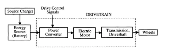
Fig.Top-level perspective of an EV system.
An EV has the following two features:
1. The energy source is portable and chemical or electromechanical in nature.
2. Traction effort is supplied only by an electric motor.
Components Of Electric vehicle: The primary components of an EV system are the motor, controller, power source, and transmission.The detailed structure of an EV system and the interaction among its various components are shown below & also shows the choices available for each of the subsystem level components.
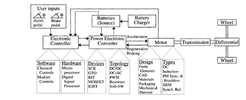
Fig.Major electrical components and choices for an EV system.
- Electrochemical batteries have been the traditional source of energy in EVs. Lead-acid batteries have been the primary choice, because of their well-developed technology and lower cost, although promising new battery technologies are being tested in many prototype vehicles. The batteries need a charger to restore the stored energy level once its available energy is near depletion due to usage.
- The majority of electric vehicles developed so far are based on DC machines, induction machines, or permanent magnet machines. The disadvantages of DC machines pushed EV developers to look into various types of AC machines. The maintenance-free, low-cost induction machines became an attractive alternative to many developers. However, high-speed operation of induction machines is only possible with a penalty in size and weight. Excellent performance together with high-power density features of permanent magnet machines make them an attractive solution for EV applications, although the cost of permanent magnets can become prohibitive.
- The electric motor is driven by a power-electronics-based power-processing unit that converts the fixed DC voltage available from the source into a variable voltage, variable frequency source controlled to maintain the desired operating point of the vehicle. The power electronics circuit comprised of power semiconductor devices saw tremendous development over the past 3 decades. The enabling technology of power electronics is a key driving force in developing efficient and high-performance power-train units for EVs.
The system level configuration for Electrical vehicles are done as follows:
- Drive cycle source & driver
- Battery pack & power converters
- Motor & motor controller
- Vehicle body
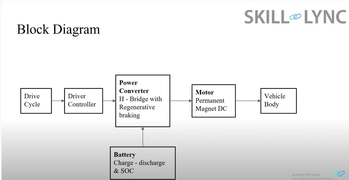
The above systems are put together to form the Electrical vehicle system on MATLAB Simulink and are discussed briefly.
Simulink Model:
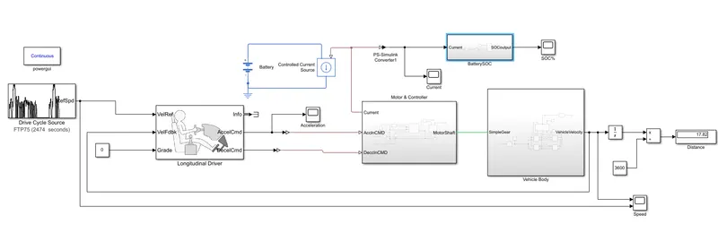
Building blocks for Simulink Model:
i)Simscape Block:
Tires,Vehicle body, Gears,Inertia,Longitudinal Driver,DC Motor,H-Bridge,Controlled PWM Voltage Source, Battery, Drive Cycle Source.
ii)Simulink Block:
Scope, Integrator. Gain, Constant, Divide, Display.
Buildng block parameter details:
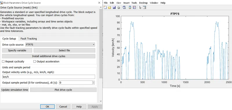
1)Drive cycle Source:Drive cycle is pre-determined data that represents the running pattern of the vehicle.
- Here we are choosing the drive cycle ‘FTP75’.
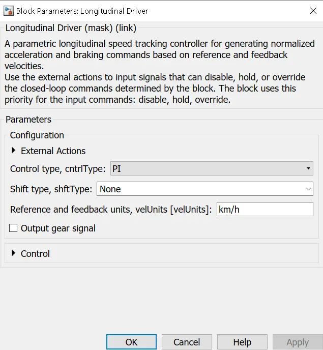
2)Longitudinal driver: The block ‘Longitudinal driver’ is used to create a longitudinal speed tracking control.
- The Drive cycle is fed into the velocity reference (VelRef)
- Velocity feedback is fed with the final velocity from the vehicle body.
- The acceleration command (AcclnCMD) & deceleration command (DecclnCMD) are given to motor controller block.
- The block’s parameter settings are shown below.
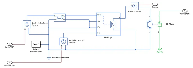
3)Motor & controller: Motor controller unit is designed to control the speed of the motor using a voltage signal with respect to input drive cycle data.
- The motor control is done with the help of 'H-Bridge' & a 'Controlled PWM Controller'.
- The acceleration & deceleration command from the longitudinal driven taken as input in his subsystem.
- The 'Controlled voltage source' receives the acceleration & deceleration command.
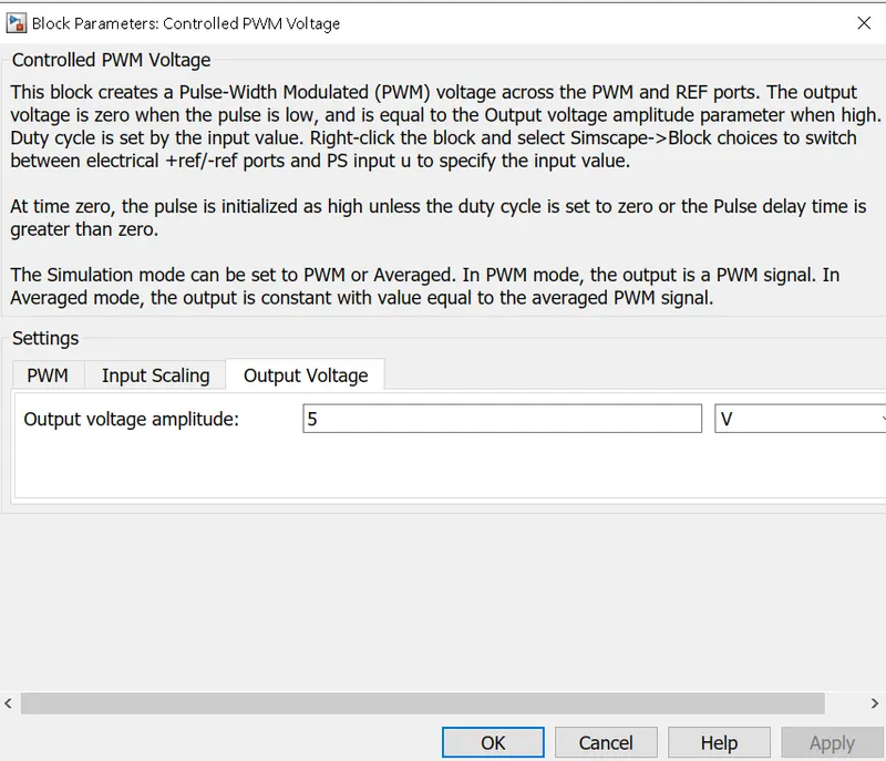
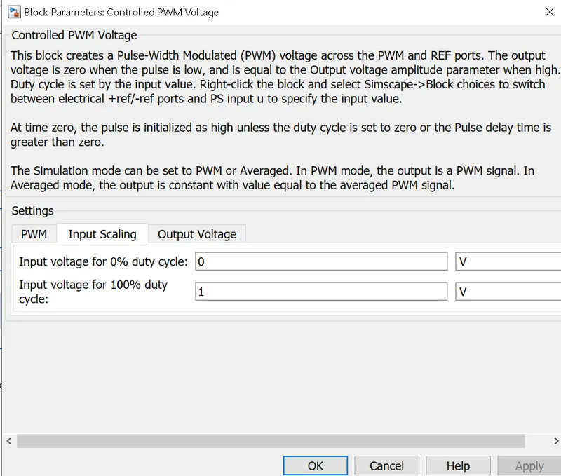
i)Controlled PWM Controller: PWM frequency is set as 3000Hz and 'Averaged' simulation mode is set as shown below.
- The acceleration command is given to the 'ref+' via the 'controlled voltage source block'.
- The reference block from the controlled voltage source, Controlled PWM Controller & H-Bridge controller are shorted and given to an 'electrical reference' & 'solver configuration block' .

ii)H-Bridge block: This block represents an H-bridge motor drive. The block can be driven by the Controlled PWM Voltage block in PWM or Averaged mode.
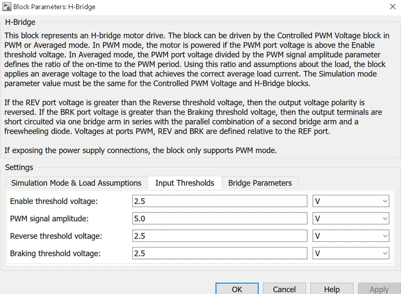
- In PWM mode, the motor is powered if the PWM port voltage is above the enabled threshold voltage.
- In Averaged mode, the PWM port voltage divided by the PWM signal amplitude parameter defines the ratio of the on-time to the PWM period.
- Connection REF is for the reference input. This combined with the PWM connected will form the pulse input for the H-Bridge.
Here, the REF input is connected to the Electrical Reference (ground). - Connection REV corresponds to the reverse motion of the motor which essentially means, the backward motion of the vehicle.
Here, the backward motion of the vehicle is not accounted for and so, the port is connected to the electrical reference. - Connection BRK is for the braking of the vehicle.
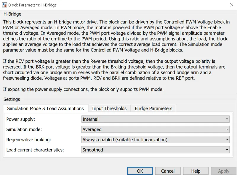
- Since, the PWM mode results in a huge amount of simulation time, Averaged mode is selected for this simulation.
- Load current characteristics are considered to be smoothed here.
- Also, the regenerative braking is anabled for the simulation. This means, when the vehicle starts decelerating, corresponding amount of charge will be fed back to the battery.
Accordingly, the BRK input is connected to a Controlled Voltage Source. This will generate emf corresponding to the intensity of brakes applied and fed the power back to the battery.
The polarity of the voltage applied across the 'DC Motor' is changed using this block. This helps the motor to run in forward & reverse direction.
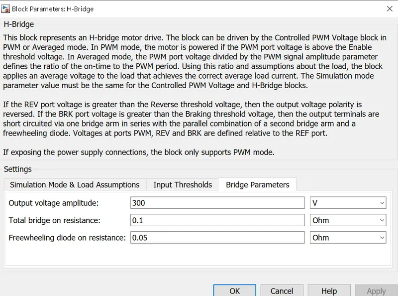
- The simulation mode, load assumptions, input threshold & bridge parameters are set as shown in the picture below.
- The output from the 'H-Bridge' block is given to the DC-Motor block and the motor input current is measured using a current sensor.
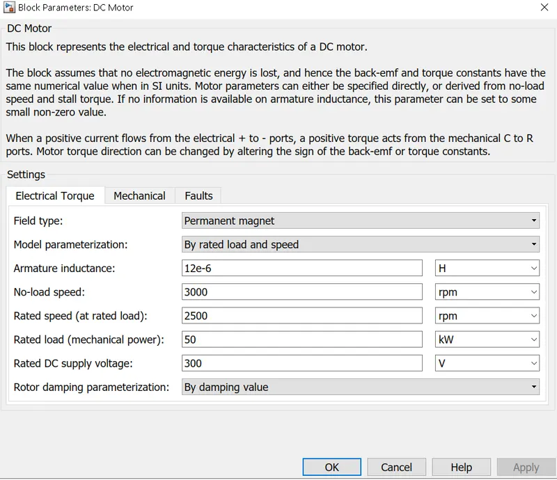
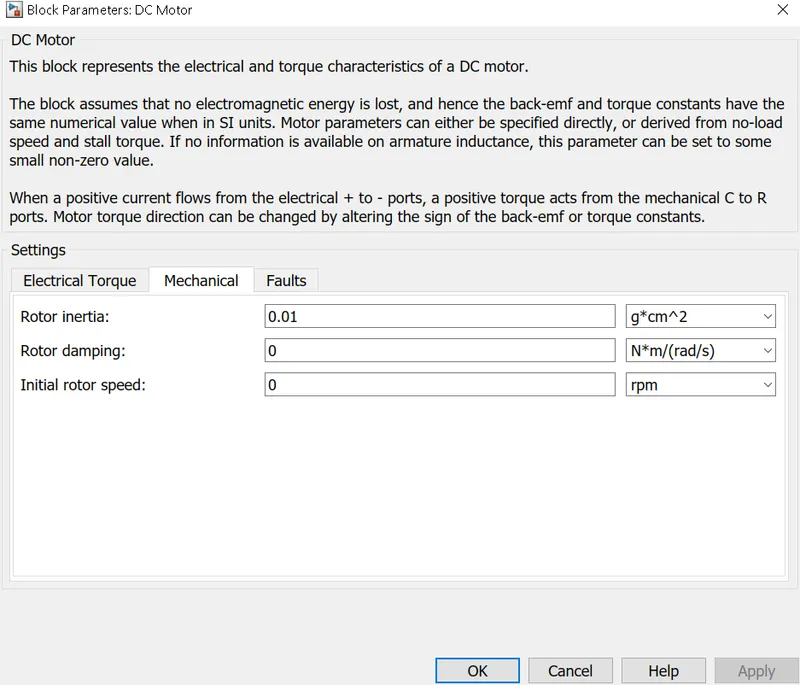
iii)DC Motor: The DC Motor block is used to convert the electrical input to mechanical output and move the vehicle.
- DC Motor also acts as generator while braking making it regenerative braking.
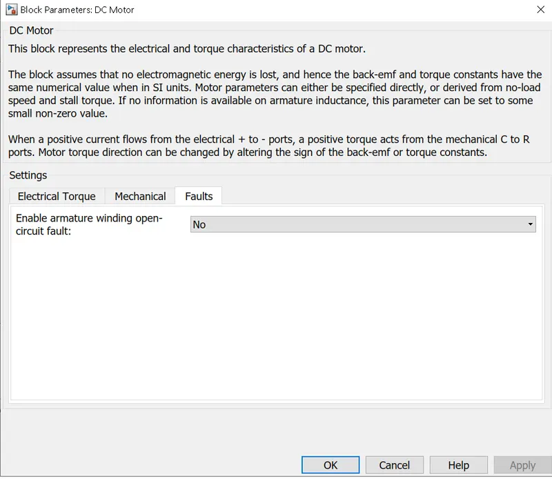
- The electric torque & mechanical parameters are set as shown below.
4)Battery:The battery of an electric car can be charged through the use of ordinary grid electricity at a specialized power station. But aside from the conventional lithium-ion battery technologies, there are also other major battery technologies which can be used for electric cars.
- Lithium-Ion Batteries : This battery technology gives extra performance and range. However, it also carries the highest price tag. Lithium-ion batteries are lighter than Lead acid and Nickel metal. These are also the batteries used in digital cameras and smartphones.
- Lead Acid Batteries : This battery technology is the most popular. It is also the cheapest among the battery technologies. What’s good about it is it’s 97% recyclable.
- Nickel Metal Hydride Batteries : This battery technology provides higher output and better performance but it costs much more than lead-acid batteries.
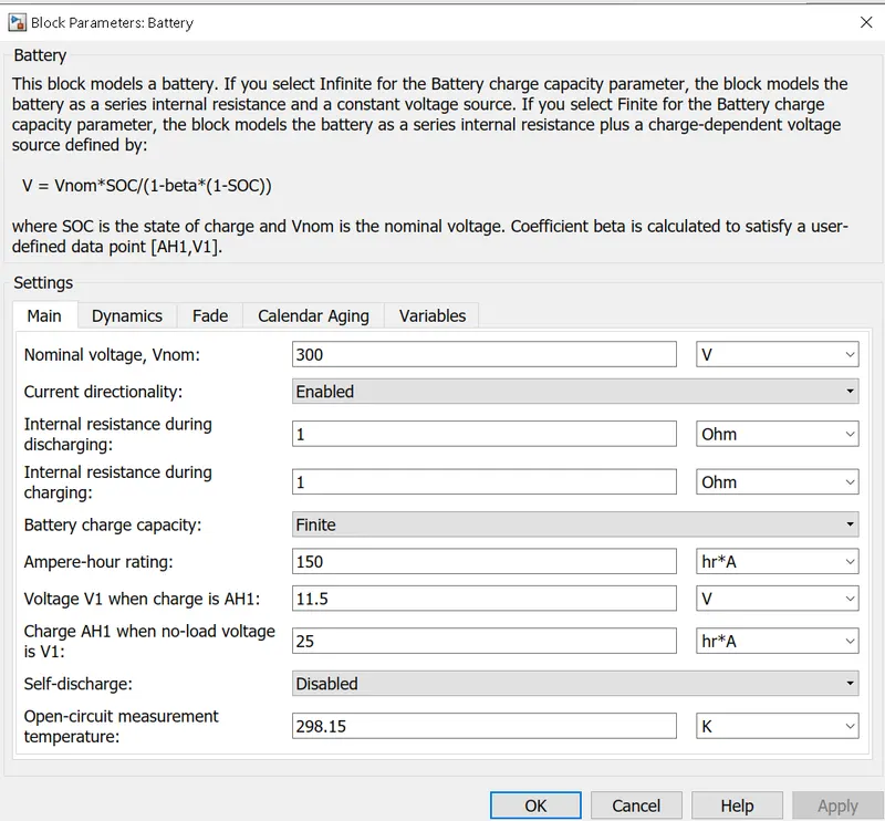
A battery block is created with a battery connected parallel with the current sensor representing the battery pack in vehicle.
- A nominal voltage of 300V is set.
- The current output from the battery pack is given to a system of 'Integrator', 'Gain' giving the SOC of the battery.
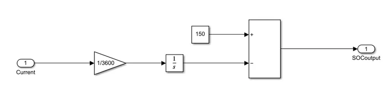
5)Vehicle Body:
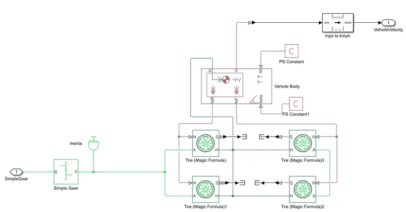
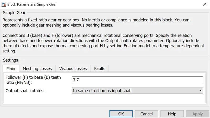
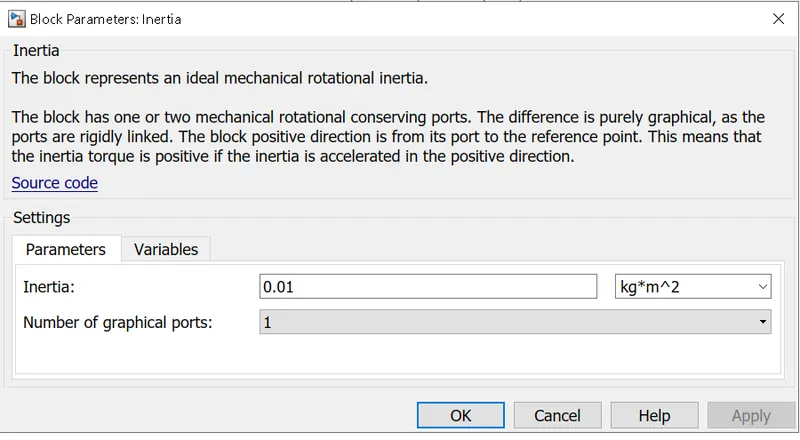
a)Simple Gear: The input to the vehicle block is given to the simple gear, its ratio is set as 3.7 and its output is given to the rear tire axle via a shaft inertia block whose inertia is 0.01.
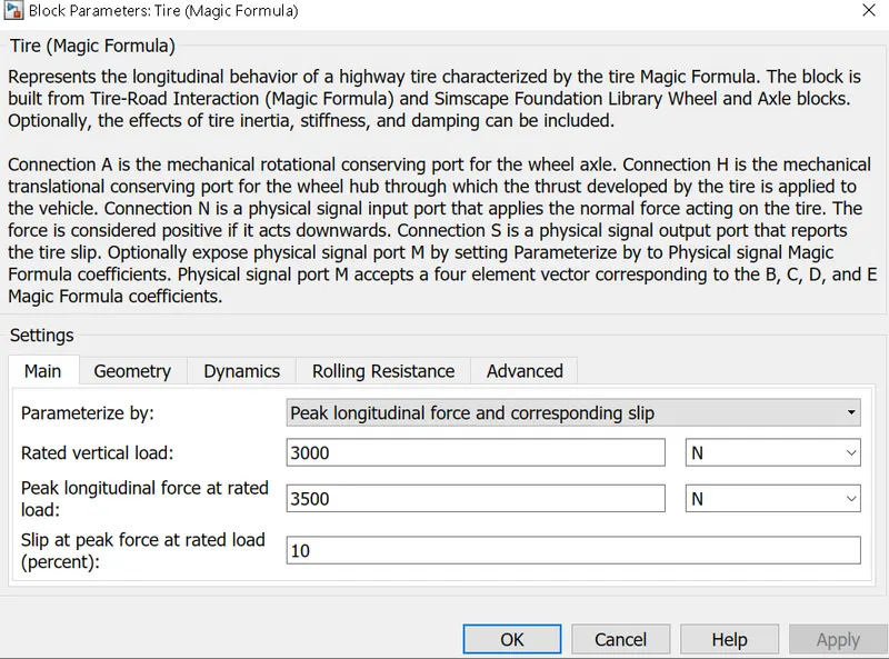
b)Tire: Tires are represented by 'Tire(Magic formula)' blocks, 4 tires represent 4 wheels in the vehicle.
- The 4 tires are arranged in as 2 front & 2 rear tires.
- Tire parameters such as nominal load capacity, rolling resistance, dynamics & geometry are defines as shown in the pictures below.
- The 'N' of the rear tires & front tires are connected to NR &NF of the vehicle body respectively.
- The 'H' all the tires are connected to 'H' of the vehicle body.
- The 'S' in all the tires are connected to terminators.
- The 'A' of front tires are shorted and that of rear tires are shorted and given to gear output 'F'.
c)Vehicle block:
- The vehicle is assumed to be a Rear axle driven (4 wheels - 2 on each axle).
- The wheels are modelled using simple Tire (Magic formula) simulink blocks.
- The N port of the tire corresponds to the Normal Reaction acting on it.
The A port corresponds to the Mechanical Rotational conserving port for the wheel axle. Thus both the wheels on the same axle should form a connection through their respective A ports.
Connection H corresponds to the Mechanical Translational conserving port for the wheel hub through which the thrust developed by the tire is applied to the vehicle. Thus, all the 4 wheels form a connection through their respective H ports and this is in turn connected to the translational hub of the vehicle body.
The connection S represents the output port for slip of the tire.
Vehicle block represent the vehicle body along with the chasis with tires and the gear. It is built using the following blocks:
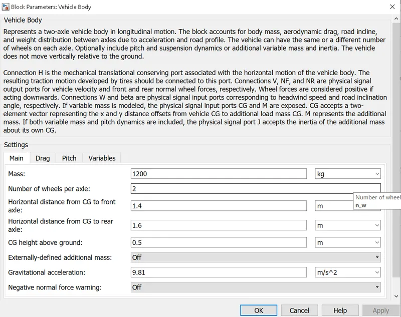
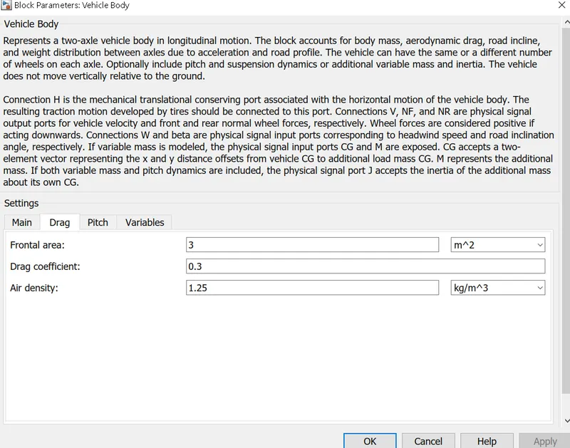
- 'Vehicle body' block has 2 input ports, 3 output ports and a connector port (H).
- Wind velocity (W) and grade angle (beta) are the input ports.
- Normal force on rear axle (NR) & Normal force on front axle (NF) are the output ports connected to 'N' of rear & front tire pairs.
- In 'Vehicle body' block, parameters such as mass, drag coefficient, air density, pitch and other variables are set and are shown the pictures below.
- Velocity (v) is taken as output and integrated to get the distance travelled by the vehicle.
d)Inertia block: The inertia acting on the shafts is given using a Inertia block. This block and its parameters are shown below,
Observation/Result:
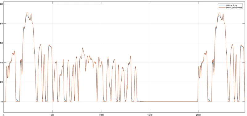
1)The first graph shows the FTP75 drive cycle for 2474 seconds and the speed travelled by the Electric vehicle.
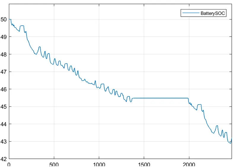
2)This graph shows the battery SOC.
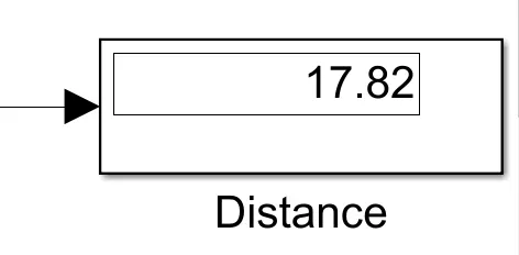
3) It shows the distance in which the vehicle has travelled in the given period of time and the display, displays the overall distance travelled by the vehicle and the total distance travelled is 17.82 Km.
Conclusion: The model was succesfully ran for simulation under the standard FTP75 drive cycle. The results have been properly analyzed. Also, learnt quite a lot of interesting things like:
- how to model an EV and carry out a real time simulation.
- how a motor controller works and what role it plays in the control of the electric motor.
- how to calculate the SOC of the battery.
- different powertrain blocks provided by simulink which can be used to simulate a vehicle model.