Final Project: Design of an Electric Vehicle
AIM:
Create a MATLAB model of electric car which uses a battery and a DC motor. Choose suitable blocks from Powertrain block set. Prepare a report about your model including following:
Objectives:
1. System level configurations
2. Model parameters
3. Results
4. Conclusion
INTRODUCTION:
An electric car is a vehicle that is propelled by one or more electric motors, using energy stored in rechargeable battery packs. These are eco-friendly and has higher efficiency compared to ICE cars. An electric vehicle is 69-72% efficient when counted against stored chemical energy and around 59-62% efficient when counted against required energy to recharge. They use electric motors for propulsion. The most common types of motors used are Permanent Magnet Synchronous Motor (PMSM) and three phase induction motor. Electric motor converts electrical energy into mechanical energy. Rotation of the motor rotor rotates the transmission. So the wheels turn and then car moves.
Various types of electric cars -
Battery electric vehicle
Hybrid electric vehicle
Plug - in Hybrid electric vehicle
Fuel cell electric vehicle
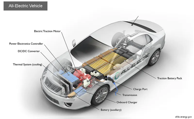
1.Battery electric vehicle
Can be charged at home overnight, providing enough range for average journeys.However, long journeys or those that require a lot of hill climbs may mean that the fuel cells require charging before you reach your destination although regenerative braking or driving downhill can help mitigate against this by charging the battery packs. Charging ranges from 30 minutes and up to more than 12 hours. This all depends on the speed of the charging station and the size of the battery.
Working principle of BEV -
Power is converted from DC battery to AC for the electric motor.
The accelerator pedal sends a signal to the controller which adjusts the vehicle speed by changing the frequency of the AC power from the inverter to the motor.
The motor connects and turns the wheels through a cog.
When the brakes are pressed or the electric car is decelerating, the motor becomes an alternator and produces power which is sent back to the battery.
Examples -
Volkswagen e - Golf, Tesla model 3, BMW i3, chevy bolt, chevy spark, Nissan LEAF, Ford Focus Electric, Hyundai Ioniq, Karma Revera.
2. Hybrid electric vehicle.
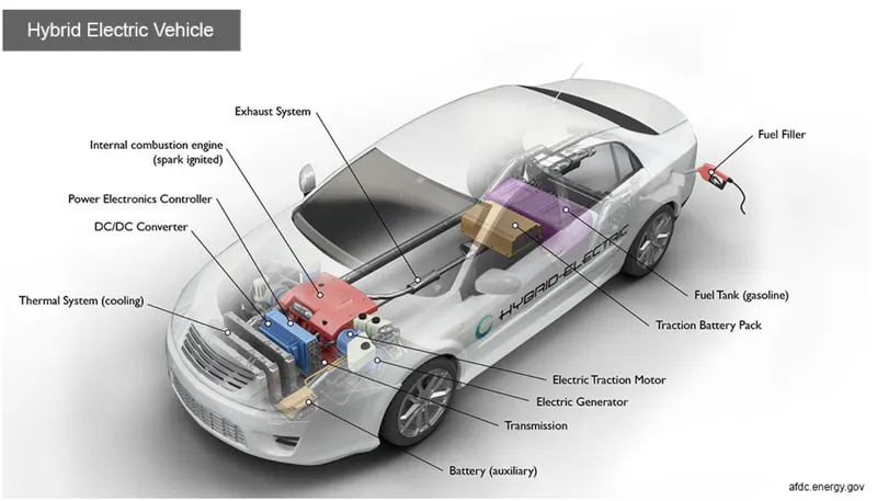
Hybrid electric vehicles are powered by an internal combustion engine and one or more electric motors, which uses energy stored in batteries. A hybrid electric vehicle cannot be plugged in to charge the battery. Instead, the battery is charged through regenerative braking and by the internal combustion engine. The extra power provided by the electric motor can potentially allow for a smaller engine. The battery can also power auxiliary loads and reduce engine idling when stopped. Together, these features result in better fuel economy without sacrificing performance.
3. Plug - in Hybrid electric vehicle
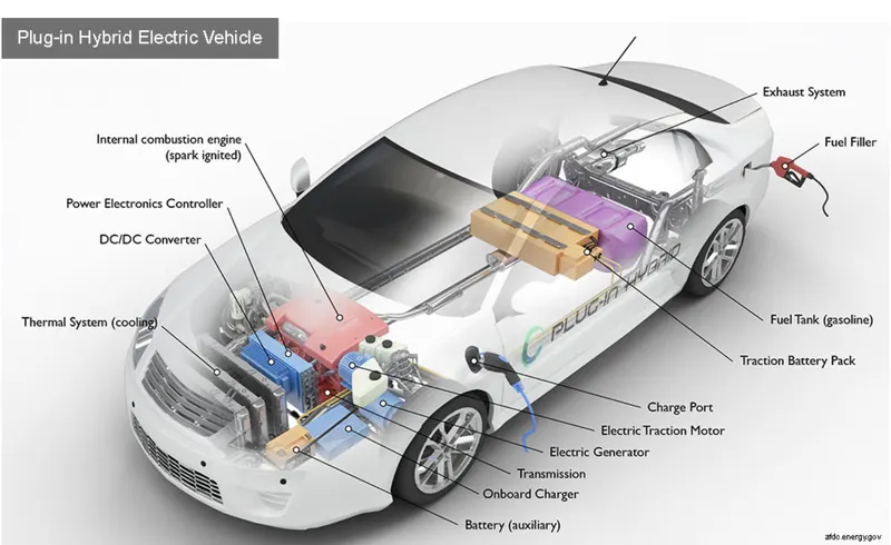
Plug-in hybrid electric vehicles (PHEVs) use batteries to power an electric motor and another fuel, such as gasoline, to power an internal combustion engine (ICE). PHEV batteries can be charged using a wall outlet or charging equipment, by the ICE, or through regenerative braking. The vehicle typically runs on electric power until the battery is nearly depleted, and then the car automatically switches over to use the ICE.
Components of PHEV
Electric Motor
Engine
Inverter
Battery
Fuel tank
Control module
Battery charger(if onboard model)
Working principle of PHEV
PHEVs typically startup in all electric mode and operate on electricity until their battery pack is depleted.
Some modelsshift to hybrid mode when they reach highway cruising speed, generally above 60 - 70 miles per hour.
Once the battery is empty, the engine takes over and the vehicle operates as a conventional, non-plug-in hybrid.
In addition to plugging into an outside electric power source, PHEV batteries can be charged by an combustion engine or regenerative braking.
During braking, the electric motor acts as generator, using the energy to charge the battery. The electric motor supplements the engine's power as a results smaller engines can be used, increasing the car's fuel efficiency without compromising performance.
Examples -
Porsche Cayenne SE - hybrid, Chevy vott, Chrysler Pacifica, Ford C - max energi, Ford fusion Energi, Mercedes C350e, Mercedes S550e etc.
4. Fuel cell electric vehicle
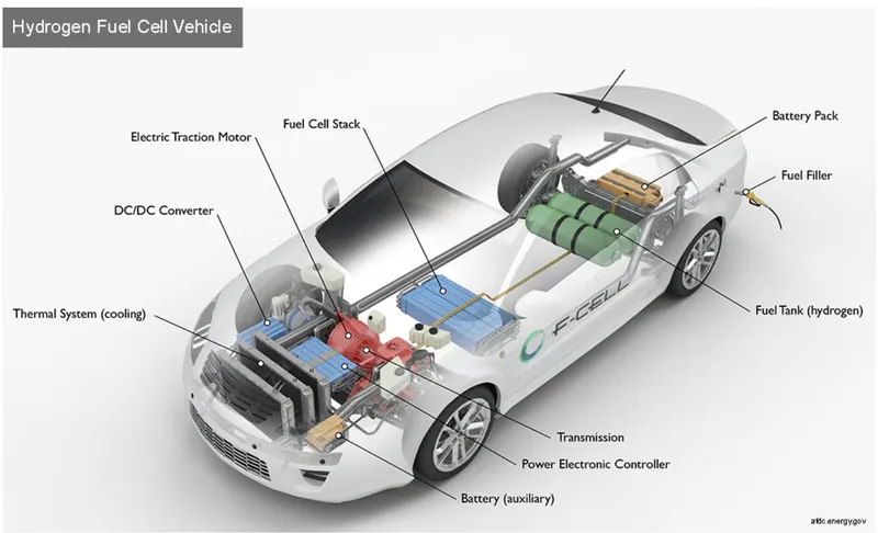
Fuel cell electric vehicles (FCEVs) use electricity to power an electric motor. In contrast to other electric vehicles, FCEVs produce electricity using a Fuel cell powered by hydrogen, rather than drawing electricity from only a battery. During the vehicle design process, the vehicle manufacturer defines the power of the vehicle by the size of the electric motor(s) that receives electric power from the appropriately sized fuel cell and battery combination. Although automakers could design an FCEV with plug-in capabilities to charge the battery, most FCEVs today use the battery for recapturing braking energy, providing extra power during short acceleration events, and to smooth out the power delivered from the fuel cell with the option to idle or turn off the fuel cell during low power needs. The amount of energy stored onboard is determined by the size of the hydrogen fuel tank. This is different from an all-electric vehicle, where the amount of power and energy available are both closely related to the battery's size.
Components of FCEV
Electric motor
Fuel cell stack
Hydrogen storage tank
Battery with converter and controller
Working principle of FCEV
The working principle of a fuel cell electric car is different compared to that of a plug - in electric car.
This type of electric cars is because the FCEV generates the electricity required to run this vehicle on the vehicle itself.
Examples
Toyota Mirai, hyundai Tuscon FCev, Riversimple rasa, Honda clarity fuel cell, Hyundai Nexa.
The most important components of electric vehicle areas:
Auxiliary Battery:
In an electric drive vehicle, the auxiliary battery provides electricity to power vehicle accessories.
Traction Battery Pack:
Traction battery pack is also known as Electric Vehicle Battery (EVB) which is used to store the electricity. Some examples of traction battery energy storage systems are as given:
Lithium-Ion
Nickel-Metal Hydride
Lead-Acid
Ultra-Capacitors
DC/DC Converter:
Basically, DC/DC converter is an electronic device which is used to converts higher-voltage DC power from the traction battery pack to the lower-voltage DC power. The converted power is used to run the vehicle accessories. It is also used to recharge the auxiliary battery.
Electric Traction Motor:
Another important component is electric traction motor and this device is used to provide motive power to the wheels.
Onboard charger:
Takes the incoming AC electricity supplied via the charge port and converts it to DC power for charging the traction battery. It monitors battery characteristics such as voltage, current, temperature, and state of charge while charging the pack.
Power electronics controller:
This unit manages the flow of electrical energy delivered by the traction battery, controlling the speed of the electric traction motor and the torque it produces.
Charge port:
The charge port allows the vehicle to connect to an external power supply in order to charge the traction battery pack.
Thermal system (cooling):
This system maintains a proper operating temperature range of the electric motor, power electronics, and other components.
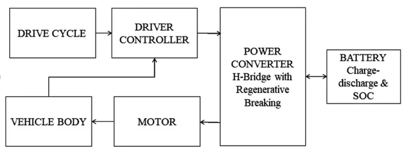
Block diagram of an electrical vehicle
Required block for creating a model of electrical vehicle:
- Vehicle body
- Tyre block
- Simple gear
- Dc motor
- H bridge
- Controlled PWM
- Controlled Volage
- Battery system
- Controlled current
- Current source
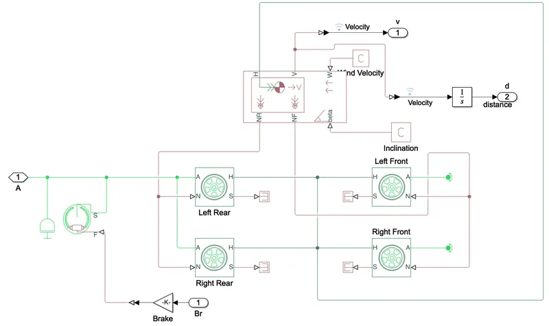
1. Vehicle body
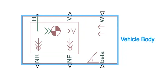
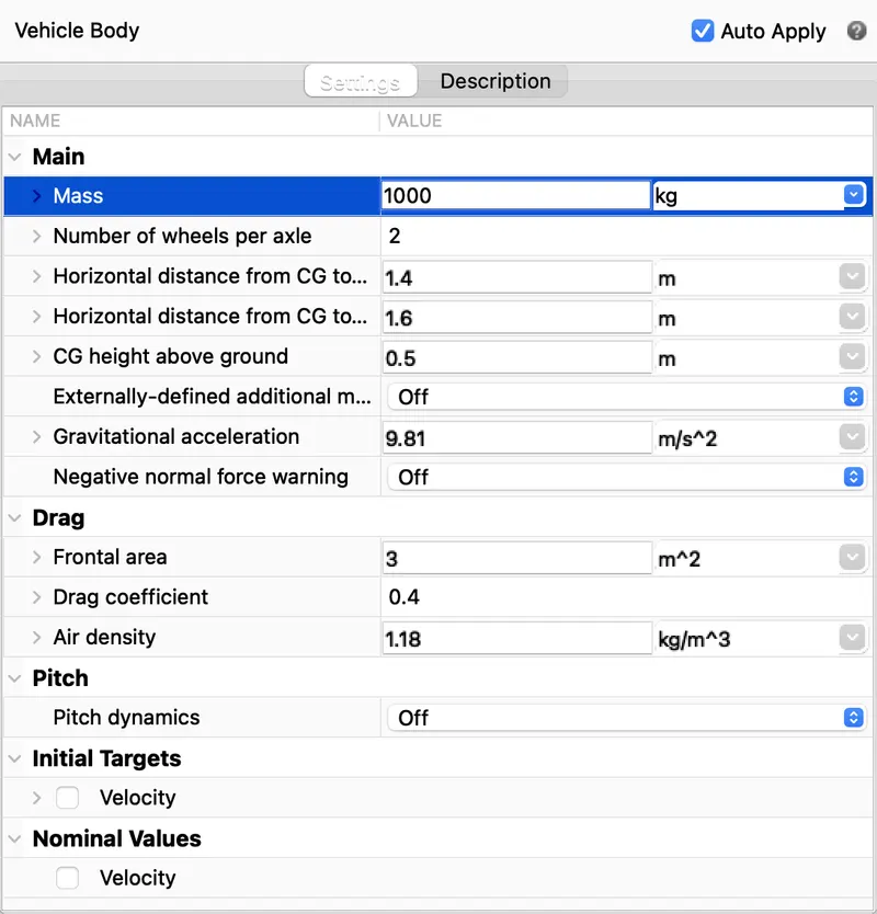
The Vehicle Body block represents a two-axle vehicle body in longitudinal motion. The vehicle can have the same or a different number of wheels on each axle. For example, two wheels on the front axle and one wheel on the rear axle. The vehicle wheels are assumed identical in size. The vehicle can also have a center of gravity (CG) that is at or below the plane of travel.The block accounts for body mass, aerodynamic drag, road incline, and weight distribution between axles due to acceleration and road profile. Optionally include pitch and suspension dynamics. The vehicle does not move vertically relative to the ground.The block has an option to include an externally-defined mass and an externally-defined inertia. The mass, inertia, and center of gravity of the vehicle body can vary over the course of simulation in response to system changes.
2. Tyre block.
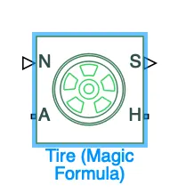
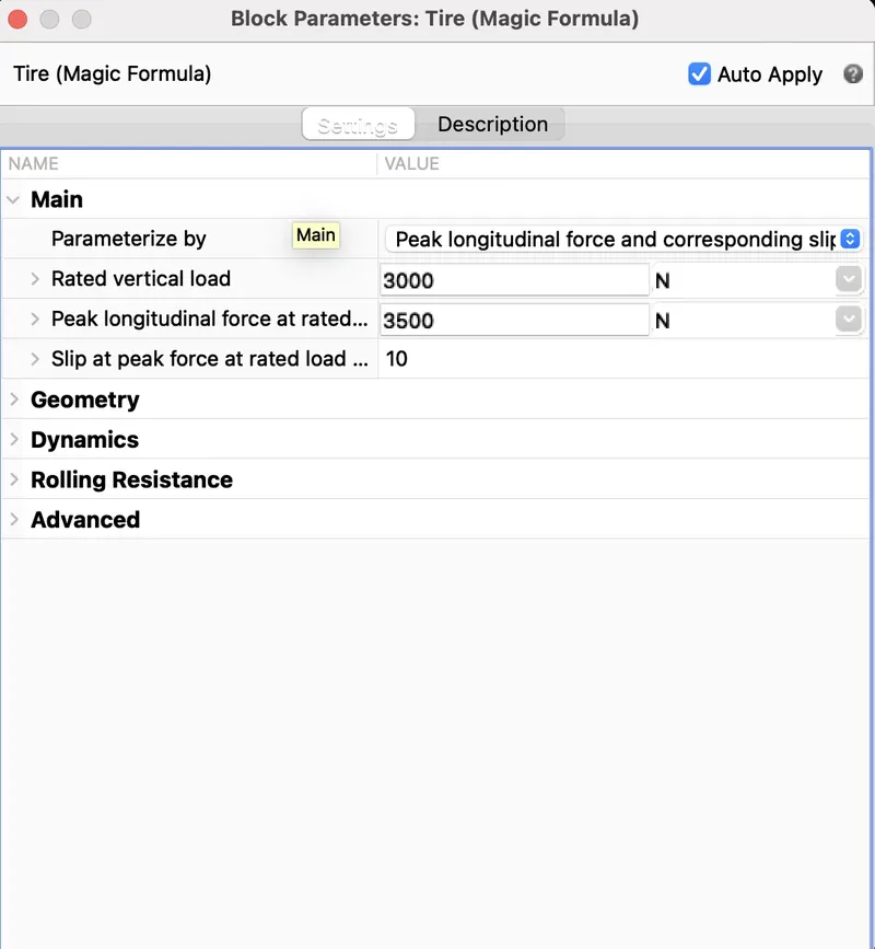
The Tire (Magic Formula) block models a tire with longitudinal behavior given by the Magic Formula [1], an empirical equation based on four fitting coefficients. The block can model tire dynamics under constant or variable pavement conditions.The longitudinal direction of the tire is the same as its direction of motion as it rolls on pavement. This block is a structural component based on the Tire-Road Interaction (Magic Formula) block.To increase the fidelity of the tire model, you can specify properties such as tire compliance, inertia, and rolling resistance. However, these properties increase the complexity of the tire model and can slow down simulation. Consider ignoring tire compliance and inertia if simulating the model in real time or if preparing the model for hardware-in-the-loop (HIL) simulation.
3.Simple gear
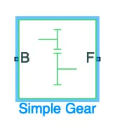
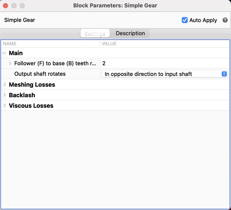
The Simple Gear block represents a gearbox that constrains the connected driveline axes of the base gear, B, and the follower gear, F, to corotate with a fixed ratio that you specify. You choose whether the follower axis rotates in the same or opposite direction as the base axis. If they rotate in the same direction, the angular velocity of the follower, ωF, and the angular velocity of the base, ωB, have the same sign. If they rotate in opposite directions, ωF and ωB have opposite signs. You can easily add and remove backlash, faults, and thermal effects.
4.Dc motor
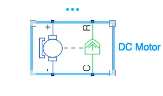
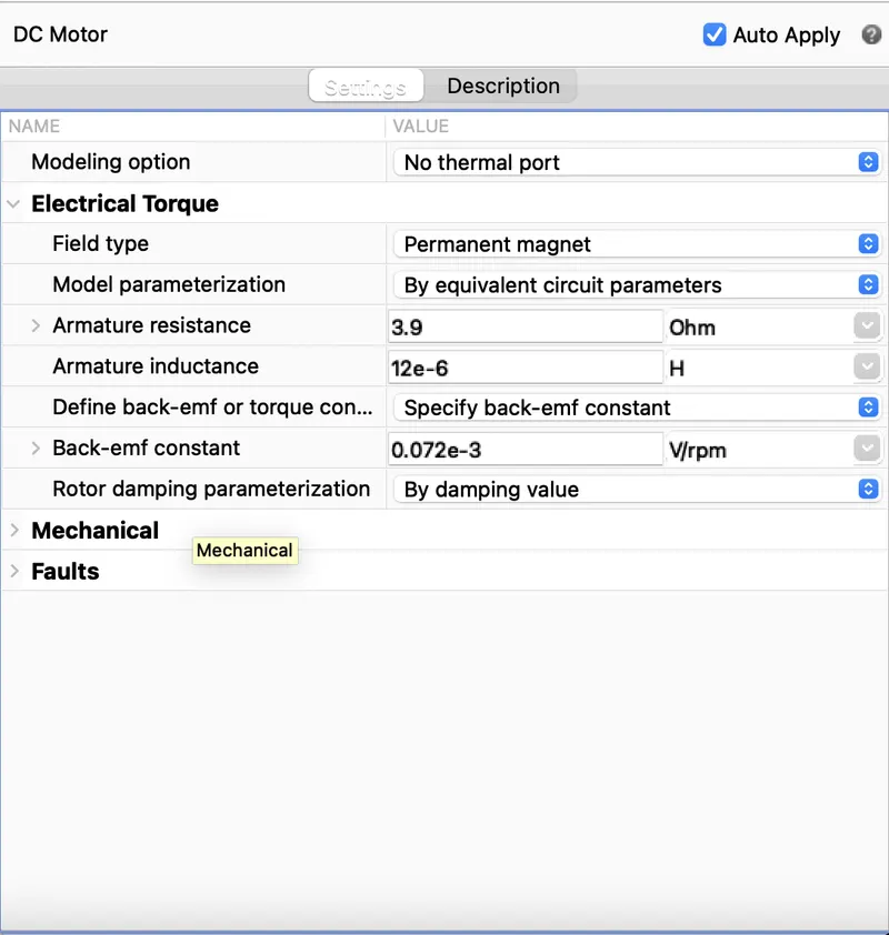
For the EV model, I have selected to use a DC motor block because DC motors are easy to model and have a very few parameters to run for a particular application. There are two sides of the block , the mechanical side is on the right and the electrical side is on the left. mechanical side has tow ports C and R, C stands for casing and is the stable part and R is the rotor which produces a torque. The electrical side has a positive and negetive side for the voltages to be applied. If positive voltage is applied to the motor block from the positive to the negetive terminal then a positive torque will act from C to R port. The directio of the torque can be cahnged by changing the sign of the back emf or the torque constant. Here i have connected the c port to the mechanical rotational reference because it will be stationary. The R port is connected to the gear in the vehicle body block.
H bridge
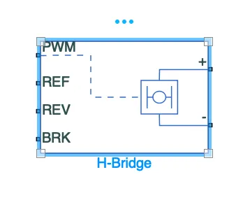
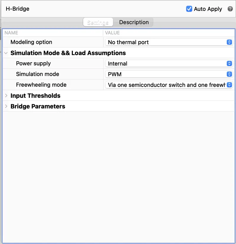
This is a power converter which is needed to provide power of the correct form and magnitude from one component to other. In case of EV,s a power converter is needed to provide a DC voltage from the battery of the EV to the DC motor, so that it can fuction properly at the required parameters.Here i have used an H-bridge motor drive as my power converter. The left side is for controlling the voltage signalsand the right side terminals to provide the controlled voltage to the DC motor the left side ports are:
Controlled PWM
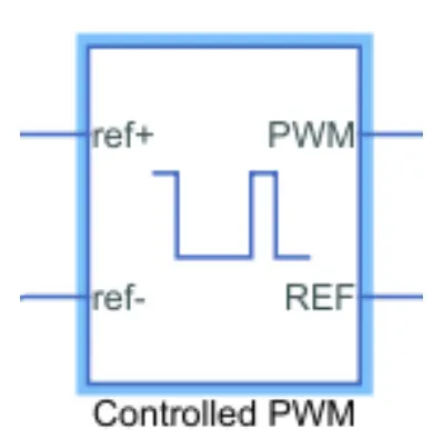
This block is used to create the pulse width modulated (PWM) voltage.Electrical input ports - The block calculates the duty cycle based on the reference voltage across its ref+ and ref- ports. This modelling variant is the default.The value of the output voltage amplitude parameter determines amplitude of the output voltage
Controlled Volage
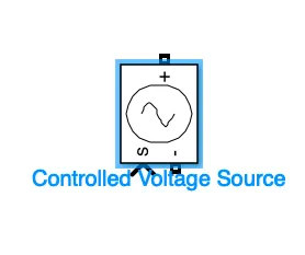
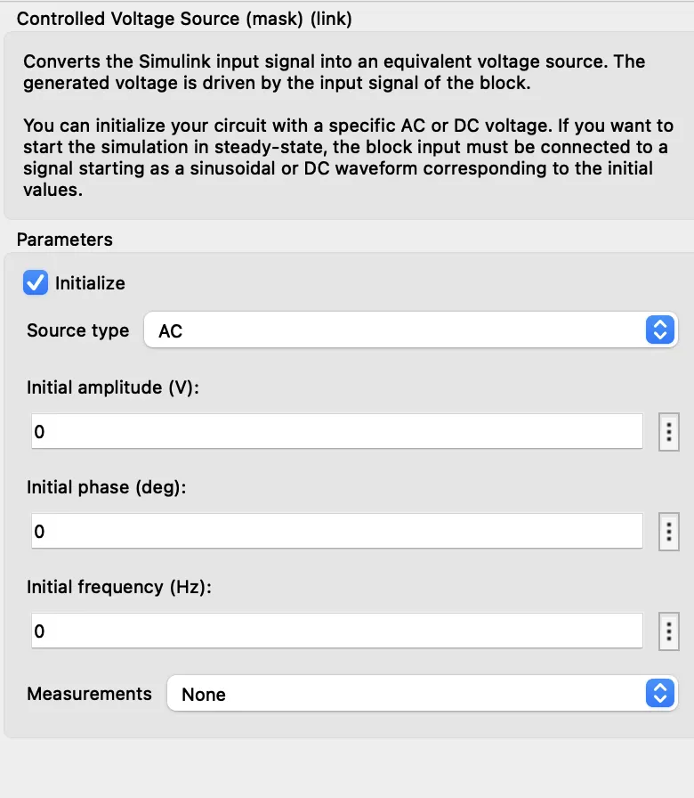
The Controlled Voltage Source block converts a Simulink® input signal into an equivalent voltage source. The generated voltage is driven by the input signal of the block.You can initialize the Controlled Voltage Source block with a specific AC or DC voltage. If you want to start the simulation in steady state, the Simulink input must be connected to a signal that begins the simulation as a sinusoidal or DC waveform that corresponds to the initial values.
Battery system
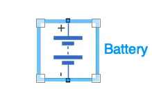
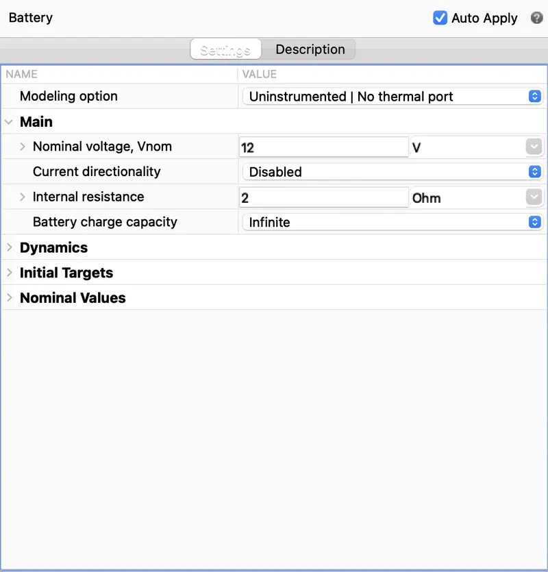
The battery will be the energy store of the EV and will contain the electrical energy in DC form and provide this energy to operate.
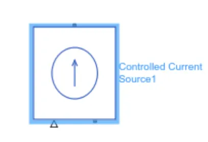
Controlled current

The Controlled Current Source block represents an ideal current source that is powerful enough to maintain the specified current through it regardless of the voltage across the source.
The output current is I = Is, where Is is the numerical value presented at the physical signal port.
The positive direction of the current flow is indicated by the arrow.
Current source
This current sensor block represents an ideal current sensor and is used to convert the current measured in an electrical circuit to a physical signal that is proportional to the current. It measures the current in the battery circuit and the DC motor. The positive and negetive terminals across which thecurrent sensor is inserted in to the circuit. The third port outputs the physical signal , In my model it sends the signal to te controlled current source.
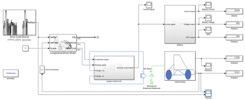
Matlab model
RESULT
Battery voltage
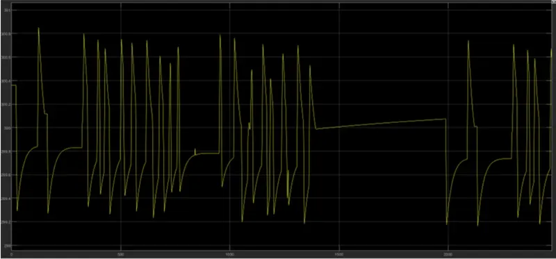
From the above result observe that the voltage varies a little bit of about 299.2 to 300.8 V due to changes speeds, acceleration and deceleration values in the model. Mainly if we observe here that it seems similar to the current values but in the opposite direction to each other.
Current signal
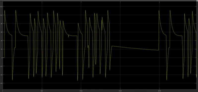
From the above result observe that it looks similar to the voltage but it in opposite to the battery current because of the connections at the battery terminals. The current signal, it gets the output based on the current that is the electrical signals passes between the H-Bridge and the DC motor.
SOC
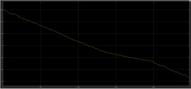
From the result we can see that battery values are discharged 57 percent and remains 43 percent in the battery. It reduces based on the given input to the battery through the current signals.
Distance
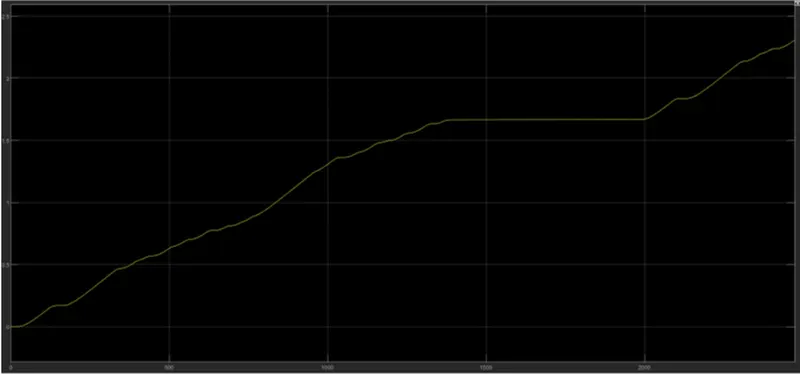
From above result that the distance travelled is located in y axis of 2.305 and x axis with time in sec of 2474 . Based on the given values to the vehicle body and the connections given to the model like axel speed weight etc its distance be calculated by the velocity from the vehicle body block with some mathematical calculations.
Conclusion
The MATLAB model of an electric car which uses a battery and a DC motor has been successfully made by choosing suitable blocks from Powertrain block set and following conclusions has been drawn from the results. From the input vs output velocity graph we can see that the EV model that we designed have traced the FTP 75 drive cycle very closely. Only when the speed suddenly drops to 0 in the FTP 75 drive cycle , the model takes time to catch up. On all other occasions the model traced the drive cycle closely.Now looking at the SOC graph we can see that almost 57% of the battery capacity is used for completing this drive cycle. From the Current variation graph we get the current of 39.09A, voltage of 300.6V, and the battery remains is 43.37%. We can also observe that by changing the values of the battery model, and vehicle body values like weight etc we will get different out put values of the battery and distance travelled. It is used in real time with some changes of space and weight with the accurate values.
Reference:
http://el-engineering.com/anatomy-of-a-battery-electric-vehicle-bev/
https://afdc.energy.gov/vehicles/how-do-fuel-cell-electric-cars-work
https://www.researchgate.net/figure/Block-diagram-of-electric-vehicle-modelling_fig1_351716419