Final Project: Design of an Electric Vehicle
EV BATCH - 17
Q) Create a MATLAB model of electric car which uses a battery and a DC motor. Choose suitable blocks from Powertrain block set. Prepare a report about your model including following:
Objectives:
1. System level configurations
2. Model parameters
3. Results
4. Conclusion
AIM :
To Create a MATLAB model of electric car which uses a battery and a DC motor. Choose suitable blocks from Powertrain block set. Prepare a report about your model including following:
- System level configurations
- Model parameters
- Results
- Conclusion
Theory:
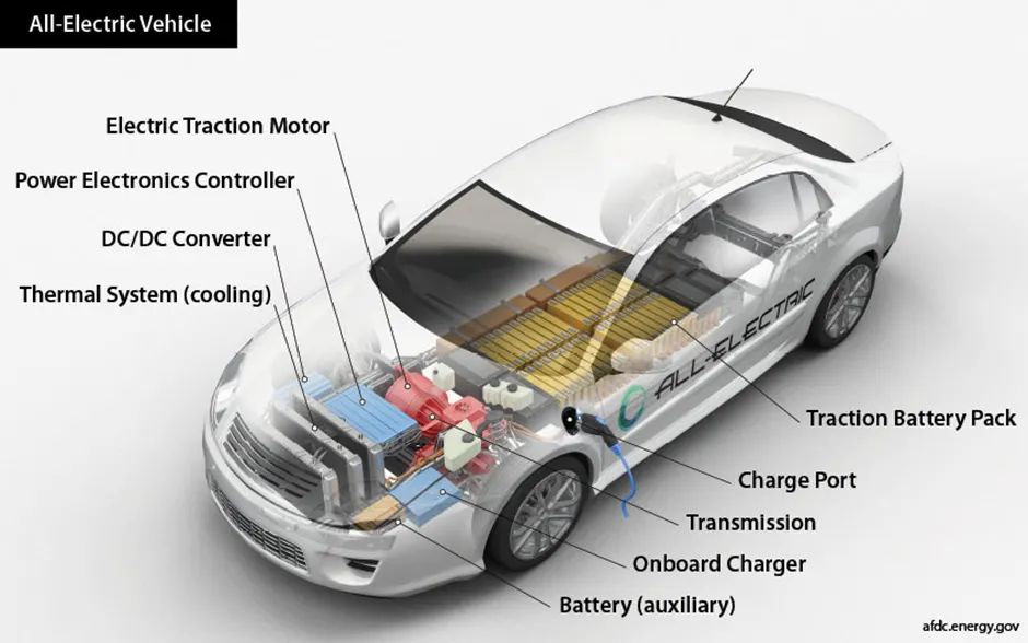
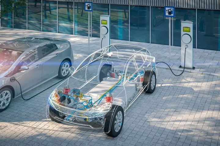
- An Electric Vehicle (EV) is a vehicle that uses one or more electric motors or traction motors for propulsion.
- An electric vehicle may be powered through a collector system by electricity from off-vehicle sources, or may be self-contained with a battery, solar panels, fuel cells or an electric generator to convert fuel to electricity. EVs include, but are not limited to, road and rail vehicles, surface and underwater vessels, electric aircraft and electric spacecraft.
- EVs first came into existence in the mid-19th century, when electricity was among the preferred methods for motor vechicle propulsion, providing a level of comfort and ease of operation that could not be achieved by the gasoline car of the time.
- Internal combustion engine were the dominant propulsion method for cars and trucks for about 100 years, but electric power remained commonplace in other vehicle types, such as trains and smaller vehicles of all types.
- Electric motive power started in 1827, when Hungarian priest Anyos jedlik built the first crude but viable electric motor, which used a stator, rotor, and commutator; and the next year he used it to power a small car.
- In 1835, professor Sibrandus Stratingh of the University of groningen, in the netherlans, built a small-scale electric car, and sometime between 1832 and 1839, Robert aderson of scotland invented the first crude electric carriage, powered by non-rechargeable primary cells.
- American blacksmith and inventor thomas davenport built a toy electric locomotive, powered by a primitive electric motor, in 1835.
- In 1838, a Scotsman named robert davidson built an electric locomotive that attained a speed of four miles per hour (6 km/h).
- In England a patent was granted in 1840 for the use of rails as conductors of electric current, and similar American patents were issued to Lilley and Colten in 1847.
- The first mass-produced electric vehicles appeared in America in the early 1900s.
- In 1902, the studebark Automobile Company entered the automotive business with electric vehicles, though it also entered the gasoline vehicles market in 1904.
- However, with the advent of cheap assembly line cars by ford motor company, the popularity of electric cars declined significantly.
- Due to lack of electricity grids and the limitations of storage batteries at that time, electric cars did not gain much popularity; however, electric trains gained immense popularity due to their economies and achievable speeds.
- By the 20th century, electric rail transport became commonplace due to advances in the development of electric locomotives.
- Over time their general-purpose commercial use reduced to specialist roles as platform trucks, forklift trucks, ambulances, tow tractors, and urban delivery vehicles, such as the iconic British milk float.
- For most of the 20th century, the UK was the world's largest user of electric road vehicles.
- In the 21st century, EVs have seen a resurgence due to technological developments, and an increased focus on renewable energy and the potential reduction of transportation impact on climate change, air project, and other environmental issues.
- Drawdown describes electric vehicles as one of the 100 best contemporary solutions for adressing climate changing.
simulation model :
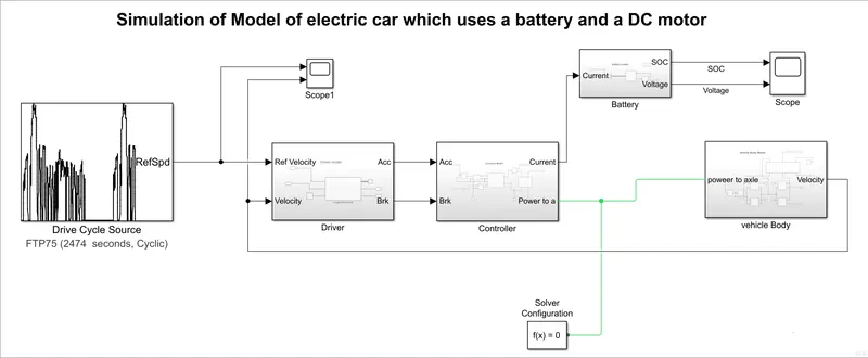
simations blocks :
- Drive Cycle source
- Driver
- controller
- Battery
- Vehicle Body
Explanation :
- First we have open the matlab app and click on the simulink then we get the simulink blank model .
- Here is connceted to driver model as a inputs of ref velocity and driver model outputs of Acc and Brk are connceted to controller inputs of Acc and Brk then we connect the output of controller is connect to battery input current then battery outputs will connceted to scope for results and the controller another output will conncet to inputs of vehocle body of power to axle and it gives a output as a velocity is given to input of driver as velocity and scope for output results.
- DRIVER CYCLE SOURCE :
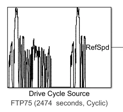
- Generates a standard or user-specified longitudinal drive cycle. The block output is the vehicle longitudinal speed.Here we taking FTP75 Drive Cycle Source
- DRIVER :
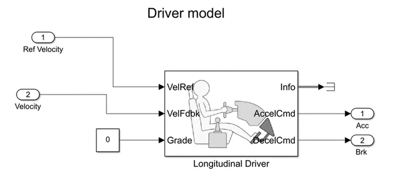
- In Driver model we have take the one longitudinal Driver and 2 inputs and 2 outputs and 1 constant and that constant value should be 'zero' and last take the terminator. The 2 inputs are connect 'VelRef' and 'VelFdbk' terminals, constant will connect to 'Grade' and info will connect to terminator and 2 outputs will conncet to AccelCmd and DecelCmd terminals.
- CONTROLLER :
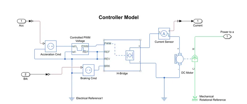
- Above simulation is Connceted as our requirement. In this we are using some practical blocks mainly Controlled PWM Voltage, H-Bridge, Dc Motor, Voltage Controller and some inputs and outputs and we have take some sensors and references . In the above given circuit we have changed some parameters values that are given below .
- CONTROLLED PWM VOLTAGE :
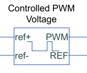
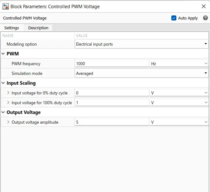
- For Controller the voltage thought PWM.
- H-BRIDGE:
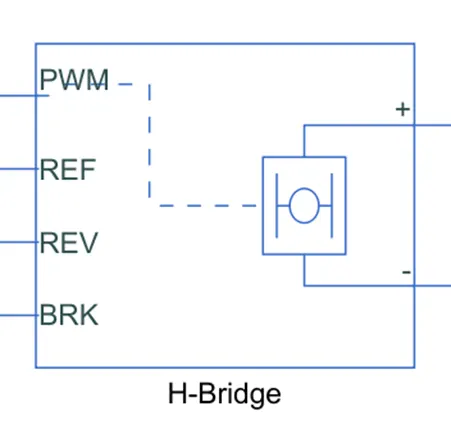
- This block is used to change the polarity of the voltage applied across the DC MOTOR so as to run the motor in forward and reverse direction as per the input command.
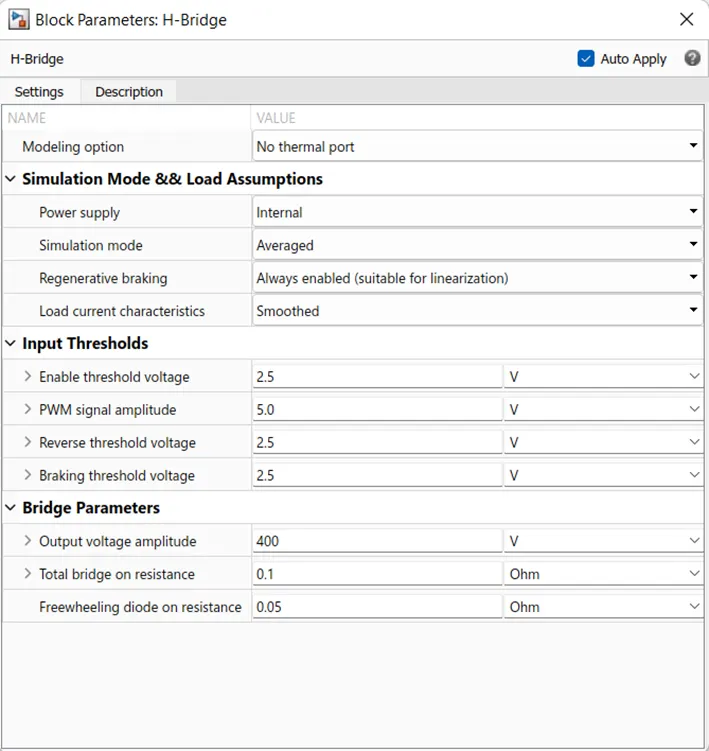
- This block changed values are given below
- DC MOTOR :
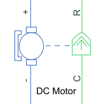
- For Converts the Electrical input to Mechanical Rotational output
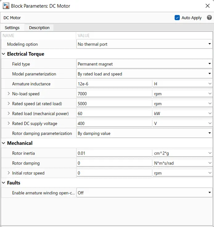
- Here the Changed parameters given below
- BATTERY :
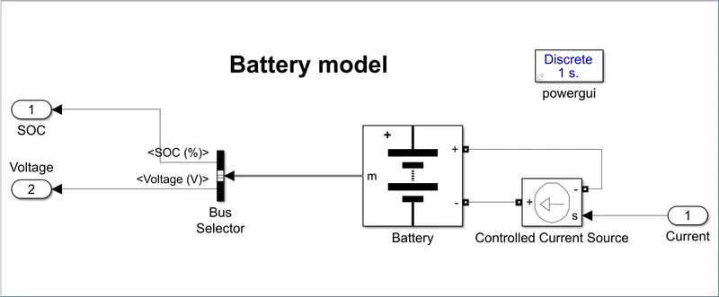
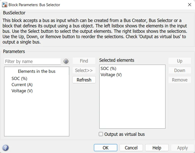
- In the Battery model we have use battery, controlled current source, Bus selector, 2 inputs and one output will connceted as per requirement
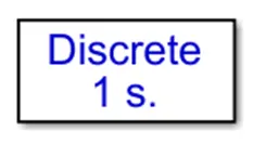
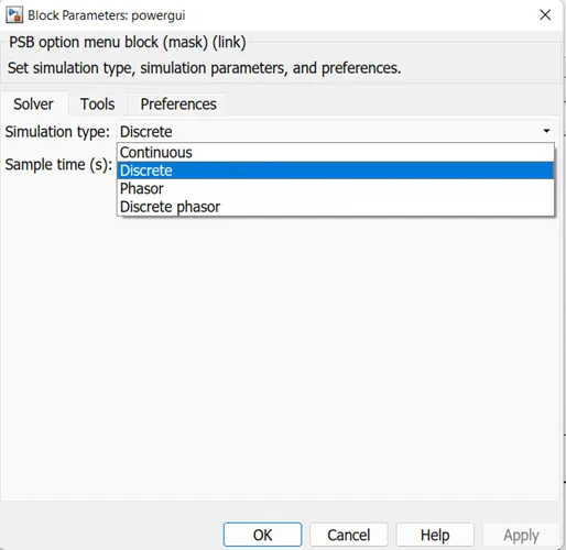
- Here we take one Powergui for Discrete 1sec signal.
- BUS SELECTOR :
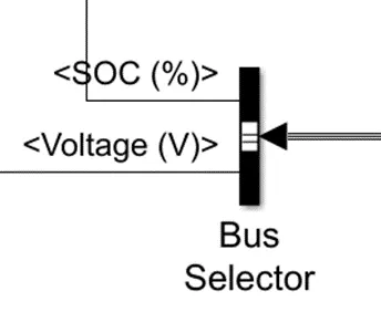
- Bus selector is for collecting the inputs
- In Bus selector we have add the SOC and voltage
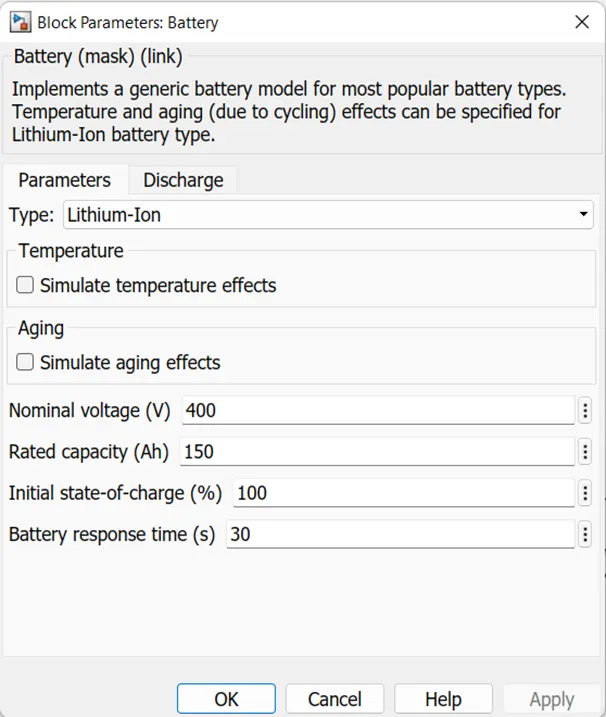
- BATTERY :
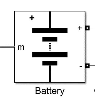
- For Giving the Supply to controller
- in battery we have take some changes that are given below
- VEHICLE BODY :
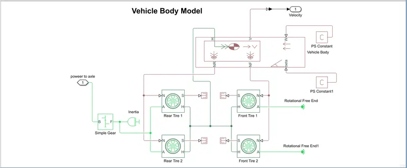
- The simulation blocks are connected according to our requirement
- in this we use 4 Tires, Simple gear, Inertia, Vehicle Body, Rotational free end and PS constant are used.
- SIMPLE GEAR :
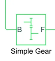
- Simple Gear is Used for Fixed Gear Box.
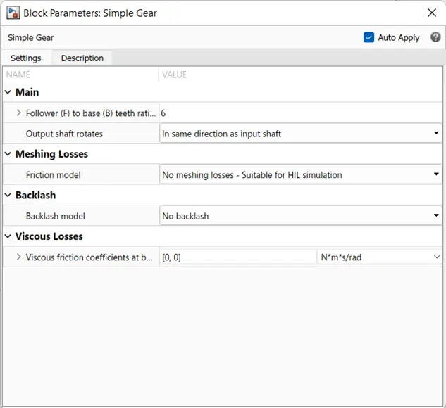
- In Smple Gear have some changes is there, they given below.
- INERTIA :
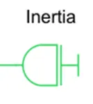
- The inertia torque is positive if the inertia is accelerated in the positive direction.
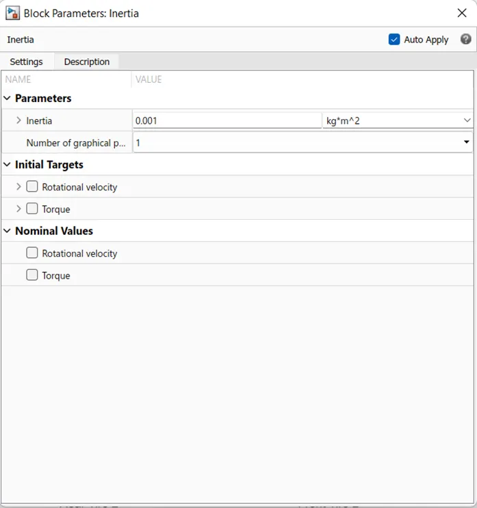
- Changes in Inertia given below.
- TIRE (MAGICAL FORCE):
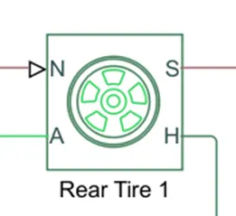
- H is hub
- S is slip
- N normal force acting on the tire
- A is the mechanical rotational conserving port for the wheel axle.
- PS CONSTANT :
- The Constant parameter accepts both positive and negative values. The block output is a physical signal port.
- In PS Constant have some changes are there is given below/
RESULTS :
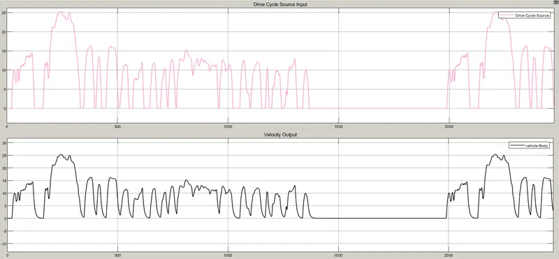
Here the simulation time taken for this block is 2474 sec for using FTP drive cycle and we get the result in the first scope is input vs output velocity graph .This scope has two inputs,one is FTP75 drive cycle and the other one is the velocity feedback. This two is combined using a bus and connection port and to the scope is connected to get this graph is given below.
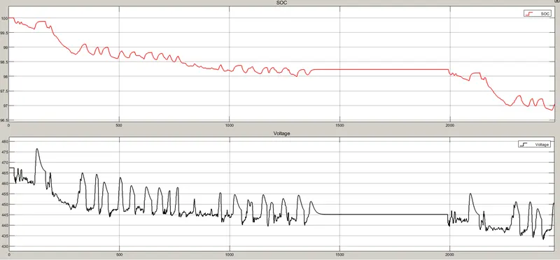
The next scope is used to get the change in soc value with respect to time The input for this scope is taken from current. Here the battery SOC about 97% and Voltage about 451V .
CONCLUSION :
Here we can design an electric vehicle and seen its performances with respect to the voltage and SOC . In this project inputs are drive cycle source as vehicle body and the out put as the battery voltage and the SOC . Intially soc is start as 100% after it executes as the 2474 seconds its discharge to 97%and the voltage value is started from 468volts and the driving for 2474seconds then the remaining voltage is to be 451volts.