Final Project: Design of an Electric Vehicle
QUESTION:Create a MATLAB model of electric car which uses a battery and a DC motor. Choose suitable blocks from Powertrain block set. Prepare a report about your model including following:
Objectives:
1. System level configurations
2. Model parameters
3. Results
4. Conclusion
AIM:MATLAB model of electric car which uses a battery and a DC motor and powerblock set suitable blocks report the model follwing objects
1. System level configurations
2. Model parameters
3. Results
4. Conclusion
THEORY:
Car Transmission
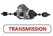
Transmission transmits moment of torsion from crankshaft to drive wheels change the size and direction of it.
Car Suspension
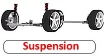
Running gear consist of the frame contains car body and all car mechanisms, the suspension (spring and shock absorber), rear and front axle and wheels.
Car Steering
Vehicle steering mechanisms contains steering system, that change the direction of a moving vehicle, and brake system provides slow down and stop full of vehicle.
«A Vehicle is a machine that transports people or cargo».
Vehicle anatomy is as interesting as human anatomy. Engine is a heart of car. Chassis are legs. Transmission – is osteo-muscular system. Car body like human body. As a man need organs as car need units, mechanisms, systems and parts.
Car Repair School
In order to explore how trucks and cars work you must consistently study materials of Vehicle Construction Book. Schema materials of website “Vehicle Anatomy” helps you to study it. So it would be nice if you study schematically material in the following sequence:
1) Purpose of Vehicle (before exploring the construction and vehicle performance is necessary to know its purpose);
2) Vehicle construction (the first step to examine the overall structure of the Vehicle, then you can begin to learn the device assemblies and other systems of the car);
3) Operating of the vehicle (if you know the Vehicle anatomy you will be easier to understand how a vehicle works.
It is almost impossible to imagine modern life any more without car. Automobiles have improved modern life through providing more convenience to people and increasing efficiency. If you want to be car driver, you should know car anatomy.
Let us also consider Truck Anatomy. The trucks have to meet European establishment of demands so construcion of it is more difficult. If you have to know fully vehicle construction and it is nessesary to learn Truck Anatomy too. If you know how to drive a Truck, so you can drive a car too.
Vehicle Construction is website, which includes ultimate guide to how cars work and free guide to every part of a vehicle. It can help you learn everything about car mechanics from our professional quality articles.
ELECTRIC CAR CONSIST OF:
System level configurations
- Battery;
- Charge port;
- DC/DC Convertor;
- Electric traction motor;
- Onboard charger;
- Power electronics controller;
- Thermal system;
- Traction battery pack;
- Transmission.
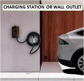
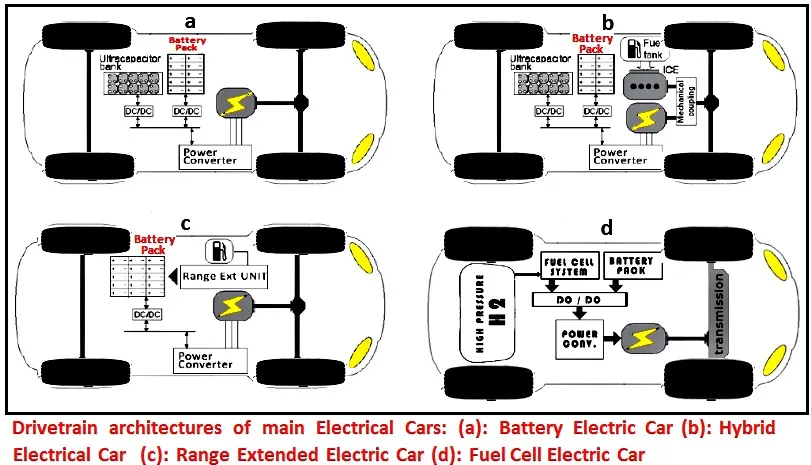
Electric vehicle have an electric motor instead of an internal combustion engine. The electric vehicle uses a large battery pack to power the electric motor. Charging station or wall outlet provides charging of the large traction battery. The proliferation of electric cars is a little difficult, because charging station were not beeing built everywhere. But I think this time will come when this initiative will become a reality. There’s information how to charge an Electric Car Step by Step, if you’re interested.
SYSTEM OF EDUCATION FOR YOUNG DRIVERS BY THEME ELECTRIC CARS
Okay, let`s go to learn main components of electric car, how an electric cars works and we`ll know answer the question: Why electric cars more better usually cars with internal combustion engine? We can learn more about electric vehicle construction and technology.
You can see the Battery (all-electric auxiliary) shown at the picture. The main purpose of the auxiliary battery is providing electricity to power vehicle accessories in an electric vehicle.
Every electric car has got own Charge Port, that allows the vehicle to connect to an external power supply in order to charge the traction battery pack. You can see the Charge Port shown at the picture too.
Vehicle accessories work need a low-voltage DC power, so electric car has mounted DC/DC converter. It`s nessasary Because device provides normal vehicle accessories work and recharge the auxiliary battery.
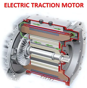
Electric traction motor drives the electric vehicle’s wheels with using power from the traction battery pack.
Onboard charger converts AC electricity to DC power for the traction battery charging. Also It has control function of main battery characteristics such as voltage, temperature, current, and state of charge while charging the pack.
Power electronics controller manages the flow of electrical energy delivered by the traction battery. Also it controlling the speed of the electric traction motor and the torque it produces.
Cooling system (thermal system) maintains a proper operating temperature range of the electric motor, power electronics, and other components.
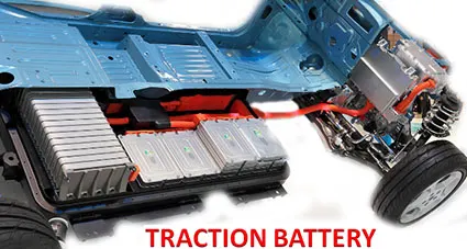
Traction battery pack provides stores electricity for use by the electric traction motor.
Electric transmission transfers mechanical power from the electric traction motor to the drive wheels.
Electric Car Safety
The weight of the battery electric car is usually heavier than a similar gasoline car. The bulk of mission accidents traditionally involve vehicle types. The occupants of a lighter car will on average suffer more and much serious than the occupants of a heavy electric vehicle by a collision. The battery location on an electric car influences an increased stability of the vehicle in emergency situation, so that may to lower the risk of an accident. The Insurance Companies in America had criticized the use of low speed electric vehicles and NEVs on public roads.
MATLAB CODE: OUTPUT CODE
power&vehicle speed
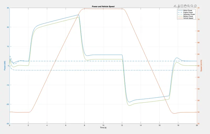
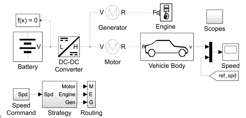
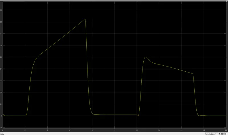
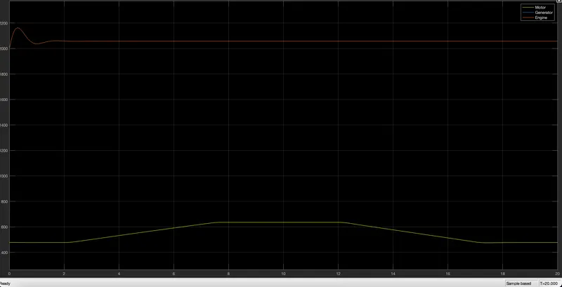
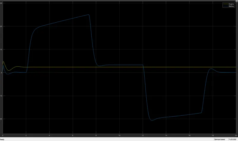
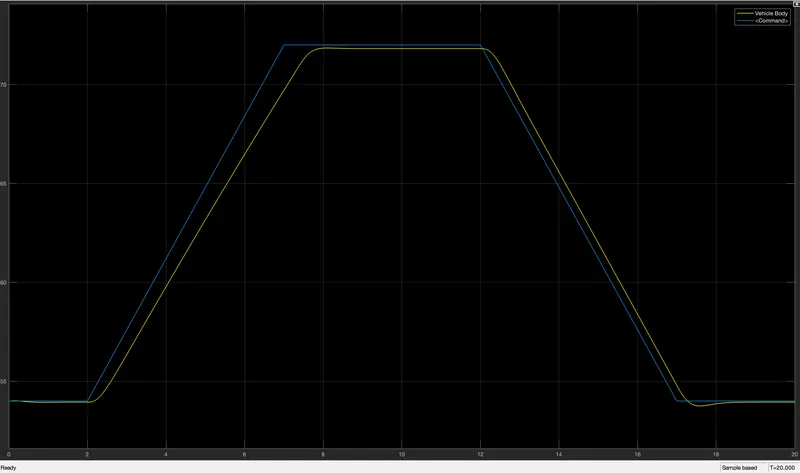
The plot below shows the flow of power from the engine, motor, and generator as the vehicle accelerates and decelerates. The generator supplies the DC network with a constant flow of power drawn from the engine. The motor draws power from the battery to accelerate the vehicle and then uses regenerative braking to feed that power back to the battery.
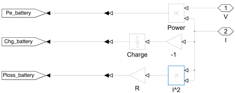
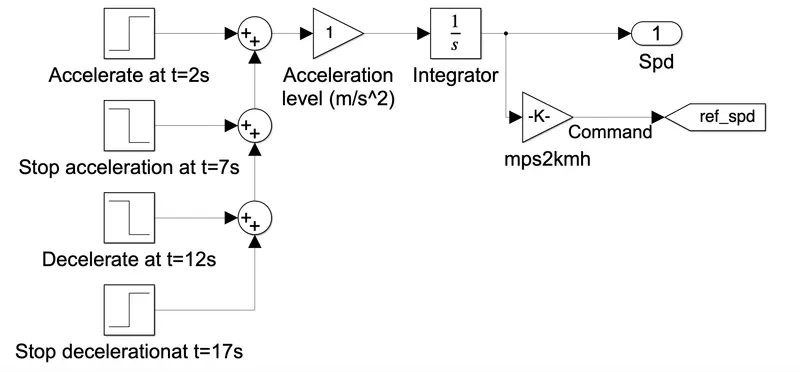
The operating voltage of different electronic devices such as ICs can vary over a wide range, making it necessary to provide a voltage for each device. the dc voltage is amplified for the adjust and run for the moror paramenters to frequent sebsequency
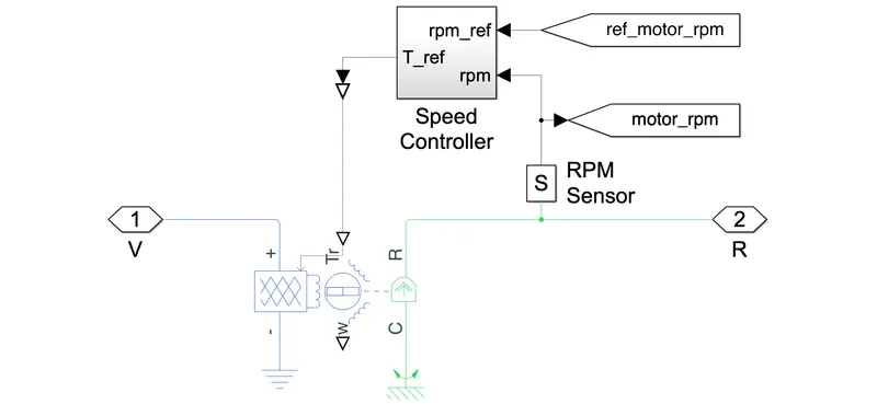
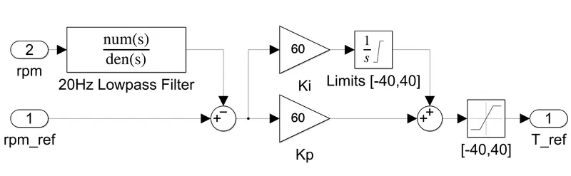
The operating voltage of different electronic devices such as ICs can vary over a wide range, making it necessary to provide a voltage for each device. an rpm sensor is avaliable to messure motor speed
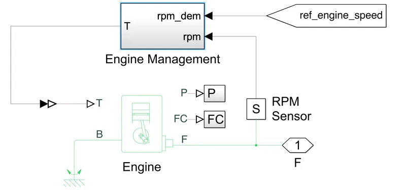
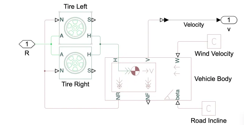

the source. The output voltage is defined by the Constant voltage parameter, and can be any real value.
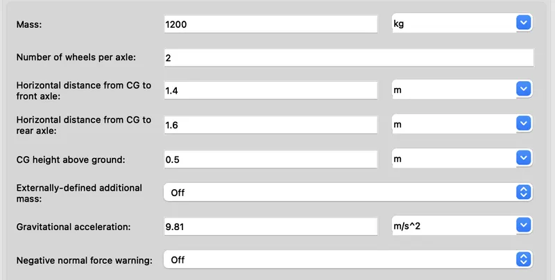
incline, and weight distribution between axles due to acceleration and road profile. The vehicle can have the same or a
different number of wheels on each axle. Optionally include pitch and suspension dynamics or additional variable mass and
inertia. The vehicle does not move vertically relative to the ground.
Connection H is the mechanical translational conserving port associated with the horizontal motion of the vehicle body. The
resulting traction motion developed by tires should be connected to this port. Connections V, NF, and NR are physical signal
output ports for vehicle velocity and front and rear normal wheel forces, respectively. Wheel forces are considered positive if
acting downwards. Connections W and beta are physical signal input ports corresponding to headwind speed and road
inclination angle, respectively. If variable mass is modeled, the physical signal input ports CG and M are exposed. CG accepts
a two- element vector representing the x and y distance offsets from vehicle CG to additional load mass CG. M represents
the additional mass. If both variable mass and pitch dynamics are included, the physical signal port J accepts the inertia of
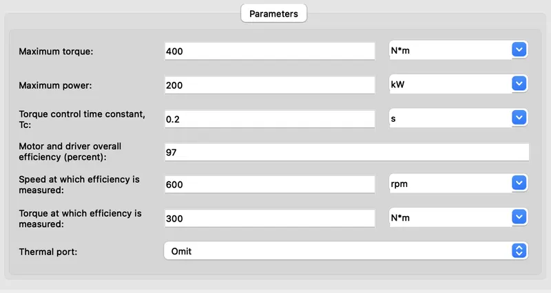
dock supports both motorina an generatina regimes, and vou can use It to represent servomotor and traction applications
at a system level. The motor's permissible range of torques and speeds is defined by a torque-speed envelope, and the
output torque tracks the torque reference demand Tr with time constant Tc.
Now the products of oxidation reaction at anode are positive ions or cations, that will flow to the cathode through the electrolyte and at the same time, products of reduction reaction at cathode are negative ions or anions, that will flow to anode through the electrolyte.
This method is highly accurate and reliable, and hence available even as a production measurement. The passing of teeth cut in a wheel, integral with the shaft, is sensed by an electronic magnitic coil The pulses generated are converted to a shaft speed, knowing the number of pulses per revolution. Two main methods may be used for this:A clock and pulse counter suits steady state operation, and as implied counts the number of pulses over a timed period. Accuracy is around 0.1%, assuming engine operation is stable.A frequency to DC converter suits transient operation, and gives a readout of instantaneous shaft speed. Again accuracy is around 0.1%.
1. how to model an EV and carry out a real time simulation
2. how a motor controller works and what role it plays in the control of the electric motor
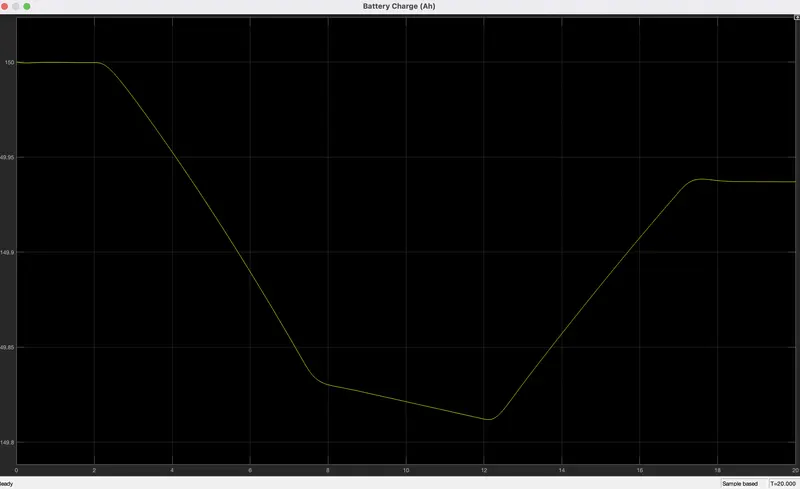
3. how to calculate the SOC& discharge of battery of the battery
4. different powertrain blocks provided by simulink which can be used to simulate a vehicle model.