Final Project: Design of an Electric Vehicle
Create a MATLAB model of an electric car that uses a battery and a DC motor. Choose suitable blocks from the Powertrain block set. Prepare a report about your model including the following:
Objectives:
1. System-level configurations
2. Model parameters
3. Results
4. Conclusion
What is an EV?
An electric vehicle (EV) is a vehicle that uses one or more electric motors for propulsion. It can be powered by a collector system, with electricity from extravehicular sources, or it can be powered autonomously by a battery (sometimes charged by solar panels, or by converting fuel to electricity using fuel cells or a generator.EVs include, but are not limited to, road and rail vehicles, surface and underwater vessels, electric aircraft, and electric spacecraft.
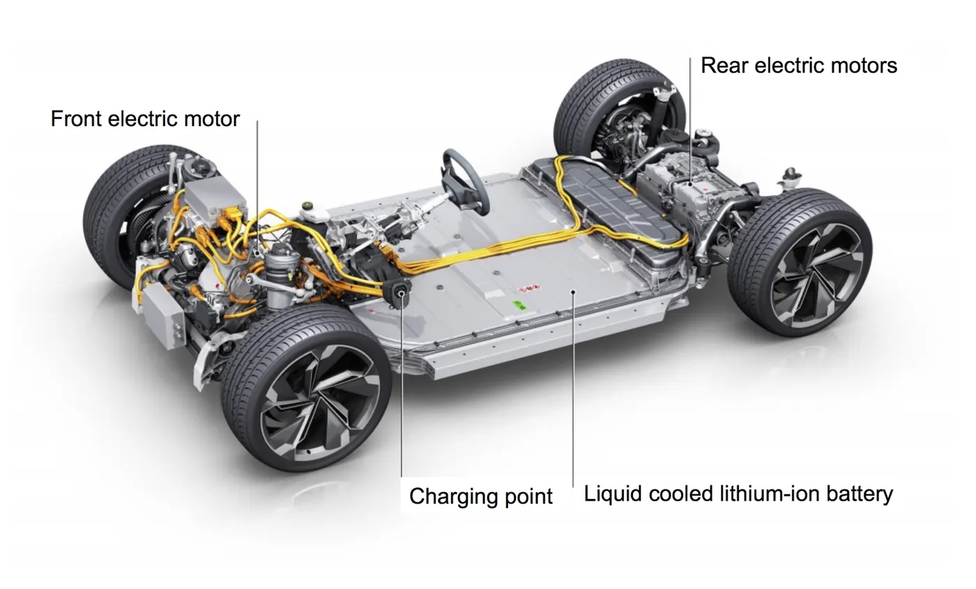
Electric car components:
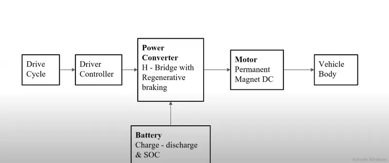
Block Diagram :
Drive Cycle:
A driving cycle is a series of data points representing the speed of a vehicle versus time.
Driving cycles are produced by different countries and organizations to assess the performance of vehicles in various ways, for instance, fuel consumption, electric vehicle autonomy, and polluting emissions.
Another use for driving cycles is in vehicle simulations. More specifically, they are used in propulsion system simulations to predict the performance of internal combustion engines, transmissions, electric drive systems, batteries, fuel cell systems, and similar components.
Driver controller:
Driver controllers are the components that are used to give the signal to the motor. this controller mainly includes an accelerator, Brakes, and a Gear shifter.
Power controller:
The motor controller is a combination of power electronics and embedded micro-computing elements which make the efficient conversion of energy stored in batteries of an electric vehicle to generate motion.
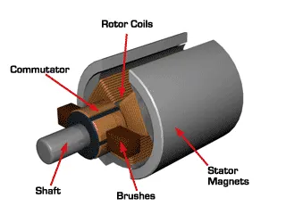
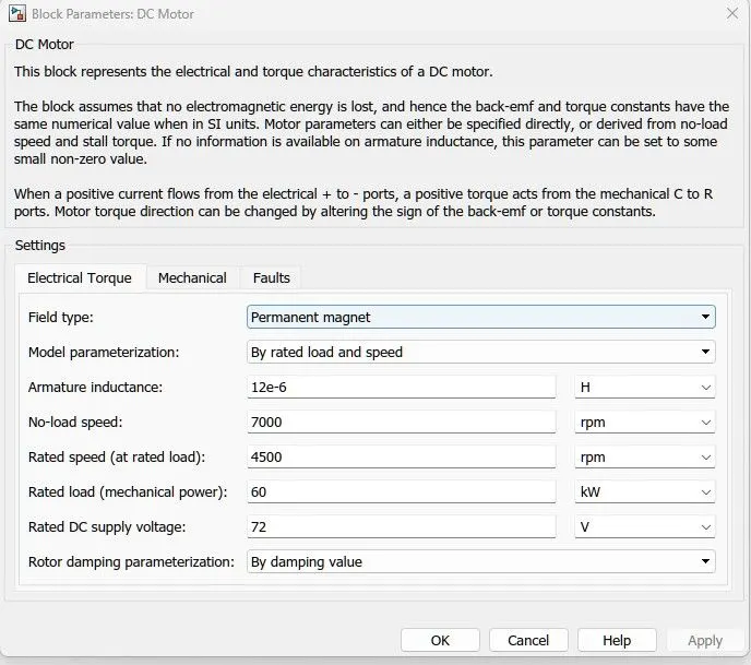
DC Motor: In the given project we used the Permanent magnet type DC Motor.
A Permanent Magnet DC motor (PMDC motor) is a type of DC motor that uses a permanent magnet to create the magnetic field required for the operation of a DC motor.
The magnets are radially magnetized and placed on the cylindrical steel stator's inner sides. This motor does not have a field coil. It generates torque by the interaction of armature flux and permanent flux. Basically, permanent magnets are used to generate the magnetic field required for DC motor operation.
Vehicle Body:
The vehicle body is the main supporting structure of a vehicle, to which all other components are attached.
The vehicle body is designed for carrying the goods (a truck) or for the carriage of passengers (passenger car). There are some kinds of vehicle bodies that differ in: by purpose (trucks, passengers, cargo-passenger, special) and by construction (skeleton, half-skeleton, non-skeleton).
Battery: An electric battery is a source of electric power consisting of one or more electrochemical cells with external connections for powering electrical devices.
System-level configurations :
The Model is created using simscape and the Simulink block sets. In which the propulsion parts and the electric parts are separated by making the subsystem which can reduce the confusion and helps in a better understanding of the model.
Following are the main blocks that are used to make the model :
Mechanical components
- Vehicle body
- magic tires
- Simple gear blocks.
Electric Components:
- DC motor (Permanent magnet)
- H-bridge
- Controlled PWM source
- Controlled voltage source
- Current sensor
- Controlled current source
- Voltage sensor
- Electric source
- Battery
- mechanical rotational reference.
Vehicle Controlled :
- Longitudinal Driver
- Multiport Switch Block
- Drive Cycle Source
- Signal Builder
- From Spreadsheet
Miscellaneous Blocks:
- Constant
- Solver
- Bus selector
- Scope
- Output port
- Input port
- Display
- Integrator
- Gain
- Divide
- Subtract
- HIT
- STOP
Mechanical components
- Vehicle body :
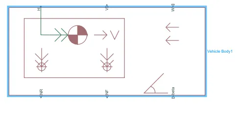
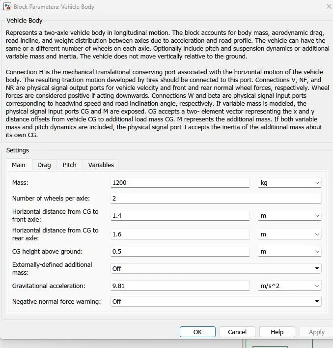
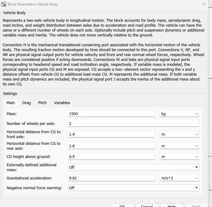
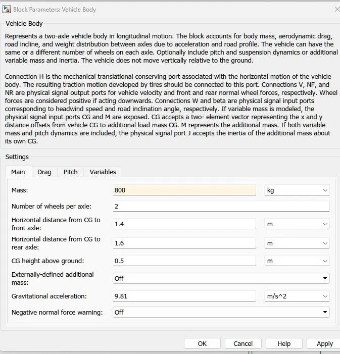
Represents a two-axle vehicle body in longitudinal motion. The block accounts for body mass, aerodynamic drag, road incline, and weight distribution between axles due to acceleration and road profile. The vehicle can have the same or a different number of wheels on each axle. Optionally include pitch and suspension dynamics or additional variable mass and inertia. The vehicle does not move vertically relative to the ground.
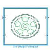
- Tire (Magic formula):
Represents the longitudinal behavior of a highway tire characterized by the tire Magic Formula. The block is built from Tire-Road Interaction (Magic Formula) and Simscape Foundation Library Wheel and Axle blocks. Optionally, the effects of tire inertia, stiffness, and damping can be included.
- Simple Gear:
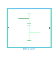
Represents a fixed-ratio gear or gearbox. No inertia or compliance is modeled in this block. You can optionally include gear meshing and viscous bearing losses.
Electric Components:
- DC motor:
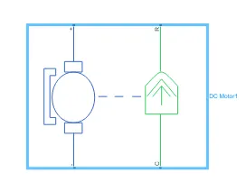
This block represents the electrical and torque characteristics of a DC motor.
The block assumes that no electromagnetic energy is lost, and hence the back-emf and torque constants have the same numerical value when in SI units. Motor parameters can either be specified directly or derived from the no-load speed and stall torque. If no information is available on armature inductance, this parameter can be set to some small non-zero value.When a positive current flows from the electrical + to - ports, a positive torque acts from the mechanical C to R ports. Motor torque direction can be changed by altering the sign of the back-emf or torque constants.
- H-bridge:
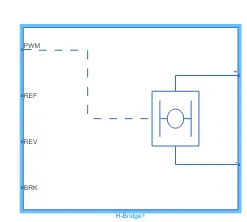
This block represents an H-bridge motor drive. The block can be driven by the Controlled PWM Voltage block in PWM or Averaged mode. In PWM mode, the motor is powered if the PWM port voltage is above the Enable threshold voltage. In Averaged mode, the PWM port voltage divided by the PWM signal amplitude parameter defines the ratio of the on-time to the PWM period. Using this ratio and assumptions about the load, the block applies an average voltage to the load that achieves the correct average load current. The Simulation mode parameter value must be the same for the Controlled PWM Voltage and H-Bridge blocks.
If the REV port voltage is greater than the Reverse threshold voltage, then the output voltage polarity is reversed. If the BRK port voltage is greater than the Braking threshold voltage, then the output terminals are short-circuited via one bridge arm in series with the parallel combination of a second bridge arm and a freewheeling diode. Voltages at ports PWM, REV, and BRK are defined relative to the REF port.
If exposing the power supply connections, the block only supports PWM mode.
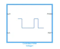
- Controlled PWM source:
This block creates a Pulse-Width Modulated (PWM) voltage across the PWM and REF ports. The output voltage is zero when the pulse is low and is equal to the Output voltage amplitude parameter when high. The duty cycle is set by the input value. Right-click the block and select Simscape->Block choices to switch between electrical +ref/-ref ports and PS input u to specify the input value.
At time zero, the pulse is initialized as high unless the duty cycle is set to zero or the Pulse delay time is greater than zero.
The Simulation mode can be set to PWM or Averaged. In PWM mode, the output is a PWM signal. In Averaged mode, the output is constant with a value equal to the averaged PWM signal.
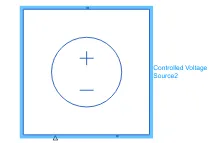
- Controlled Voltage Source:
The block represents an ideal voltage source that is powerful enough to maintain the specified voltage at its output regardless of the current passing through it. The output voltage is V = Vs, where Vs is the numerical value presented at the physical signal port.
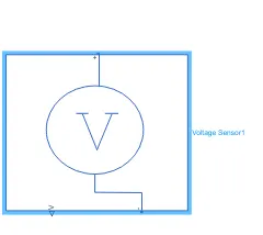
- Voltage Sensor:
The block represents an ideal voltage sensor, that is, a device that converts voltage measured between any electrical connections into a physical signal proportional to the voltage.
Connections + and - are conserving electrical ports through which the sensor is connected to the circuit. Connection V is a physical signal port that outputs voltage values.
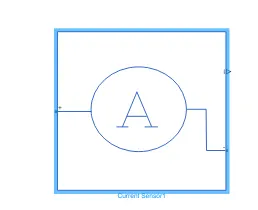
- Current Sensor:
The block represents an ideal current sensor, that is, a device that converts current measured in any electrical branch into a physical signal proportional to the current.
Connections + and - are conserving electrical ports through which the sensor is inserted into the circuit. A connection I is a physical signal port that outputs the current value.
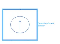
- Controlled Current source:
The block represents an ideal current source that is powerful enough to maintain the specified current through it regardless of the voltage across it. The output current is I = Is, where Is is the numerical value presented at the physical signal port.
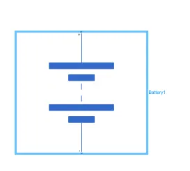
- Battery:
This block models a battery. If you select Infinite for the Battery charge capacity parameter, the block models the battery as a series of internal resistance and a constant voltage source. If you select Finite for the Battery charge capacity parameter, the block models the battery as a series of internal resistance plus a charge-dependent voltage source defined by:
V = Vnom*SOC/(1-beta*(1-SOC))
where SOC is the state of charge and Vnom is the nominal voltage. Coefficient beta is calculated to satisfy a user-defined data point [AH1,V1].
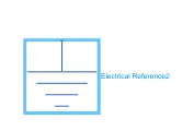
- Electric Reference:
Electrical reference port. A model must contain at least one electrical reference port (electrical ground).
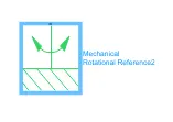
- Mechanical Rotational Reference:
This block represents a mechanical rotational reference point, that is, a frame or a ground. Use it to connect mechanical rotational ports that are rigidly affixed to the frame (ground).
Vehicle Controlled :
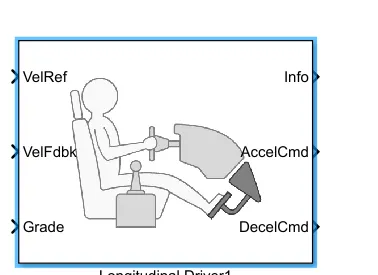
- Longitudinal Driver :
A parametric longitudinal speed tracking controller for generating normalized acceleration and braking commands based on reference and feedback velocities.
Use the external actions to input signals that can disable, hold, or override the closed-loop commands determined by the block. The block uses this priority for the input commands: disable, hold, override.
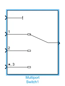
- Multiport Switch:
Pass through the input signals corresponding to the truncated value of the first input. The inputs are numbered top to bottom (or left to right). The first input port is the control port. The other input ports are data ports.
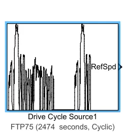
- Drive Cycle :
Generates a standard or user-specified longitudinal drive cycle. The block output is the vehicle's longitudinal speed. You can import drive cycles from:
- Predefined sources
- Workspace variables, including arrays and time series objects
- mat, Xls, xlsx, or txt files
Use the fault tracking parameters to identify drive cycle faults within the specified speed and time tolerances.
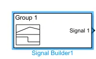
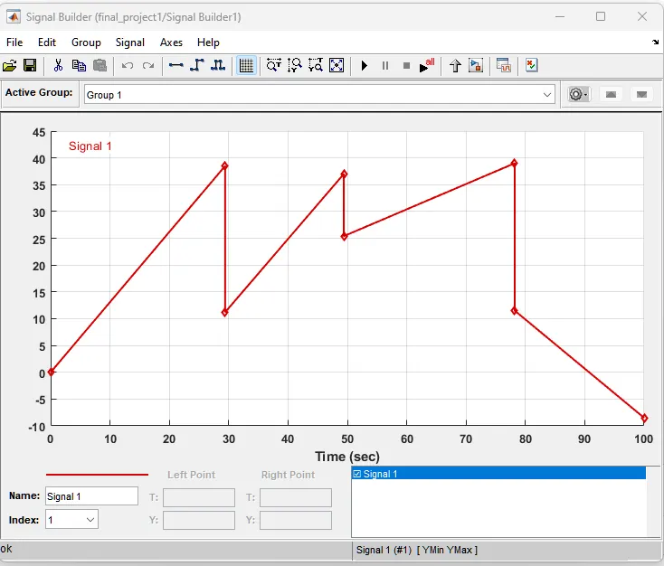
- Signal Builder:
The signal builder builds the signal according to the user's requirement. The X-axis is a time axis and the Y-axis is the variable that the user wants to change w.r.t time. The signal builder contains points that can be slide by the mouse.
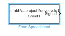
- From spreadsheet:
Read data values from the spreadsheet.
The block interprets the first column as time and the first row and remaining columns as signals.
If there are empty signals, the block returns an error at import.
Fill in all the headings in the columns. If all headings are blank, the block assigns default signal headings using the format Signal#.
Miscellaneous Blocks:
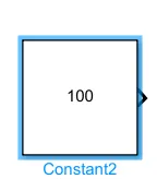
- Constant :
Output the constant specified by the 'Constant value' parameter. If 'Constant value' is a vector and 'Interpret vector parameters as 1-D' is on, treat the constant value as a 1-D array. Otherwise, output a matrix with the same dimensions as the constant value.
- Solver :
Defines solver settings to use for simulation.
- Bus selector:
This block accepts a bus as input which can be created from a Bus Creator, Bus Selector or a block that defines its output using a bus object. The left list box shows the elements in the input bus. Use the Select button to select the output elements. The right list box shows the selections. Use the Up, Down, or Remove button to reorder the selections. Check 'Output as virtual bus' to output a single bus.
- HIT:
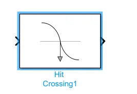
Detects when the input signal reaches the Hit crossing offset parameter value in the direction specified by the Hit crossing direction parameter. You can configure the block to output a signal, a SimEvents message, or a function-call event. If the input signal crosses the offset value in the specified direction, the block outputs 1 for the Signal Output type, a SimEvents message for the Message Output type, or a single function call for the Function-Call Output type. The SimEvents message contains the crossing type, index, time and offset of the hit crossing event.
- STOP:
Stop simulation when input is nonzero.
Working of the model: The EV model takes the signals from the multi-switch port which is connected to the different sources which describe the driving conditions (Acceleration and the deceleration). The longitudinal driving block takes the signal and according to that, it transmits acceleration and deceleration commands to the controlled voltage source. which generates the PWM (pulse width modulation) in the form of a signal and transmits it to the PWM voltage block. The pulses are transmitted in the two outputs i.e, the PWM and the reference of the H-bridge. There are two controlled voltage blocks used to transmit the acceleration and the regenerative braking signals to the PWM voltage. In the model, the reverse scenario is not considered. the DC motor electric part is connected to the positive terminal and the negative terminal of the H-Bridge. the battery is connected to the current source with H-bridge for the regenerative braking. the rotor of the motor fluctuates the speed according to the duty cycle which is maintained by the PWM signals.
The speed is then transmitted to the simple gear with the help of the shaft which transmits the required torque and speed to the wheel which is connected to the vehicle body. the vehicle body is the block that represents the car having mass and axle and the vehicle dynamics parameters.
Steps for making the model:
- The vehicle body block is taken from the library
- After which the 4 magic wheel block is taken and the hub part of the wheel is connected to each other and then connected to the vehicle body hub port. The front and rear wheel axle is also connected to the vehicle body respectively
- Then the simple gear is connected to the rear wheels
- Now the input shaft of the gear is connected to the DC motor mechanical part and the mechanical rotational reference is connected to the casing of the motor.
- The positive terminal of the motor is connected H-Bridge and the current sensor.
- The current sensor is then connected to the current source and the battery.
- Now, the input ports PWM and the reference of the H-bridge are connected to the controlled PWM voltage block.
- the reverse port of the H-bridge is connected to the electric reference and the Brake port is connected to the controlled voltage source
- The PWM voltage block positive terminal is connected to the Controlled voltage source which is connected to the acceleration pedal of the longitudinal driver block.
- The Longitudinal output signals are basically acceleration and deceleration which are connected to the respective input of the Electric part of the model
- the longitudinal driver blocks take input from the multiport switch.
- The multiport switch is connected to the Drive cycle source blocks, signal builder, and the From spreadsheet block which creates the different driving scenarios.
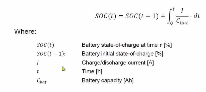
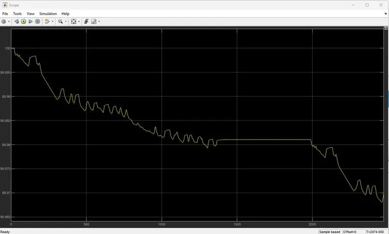
State of Charge (SoC) is the level of charge of an electric battery relative to its capacity. The units of SoC are percentage points (0% = empty; 100% = full). An alternative form of the same measure is the depth of discharge (DoD), the inverse of SoC (100% = empty; 0% = full). SoC is normally used when discussing the current state of a battery in use, while DoD is most often seen when discussing the lifetime of the battery after repeated use.
In a battery electric vehicle (BEV), hybrid vehicle (HV), or plug-in hybrid electric vehicle (PHEV), SoC for the battery pack is the equivalent of a fuel gauge. It is important to mention that the state of charge, presented as a gauge or percentage value on any vehicle dashboard, especially in plug-in hybrid vehicles, may not be representative of a real level of charge. In that particular case, some noticeable amount of energy stored in the electric battery is not shown on the dashboard and is reserved for hybrid-work operations. It permits a vehicle to accelerate with electric motors mainly using battery energy, while the petrol engine serves as a generator and recharges the battery to the minimum level needed for such operation. Examples of such cars are Mitsubishi Outlander PHEV (all versions/years of production), where 0% of the state of charge presented to the driver is a real 20-22% of charge level (assuming zero level as the lowest level of charge permitted by car producer). Another one is the BMW i3 REX (Range Extender version), where about 6% of SOC is reserved for PHEV-alike operations. Tesla has stated that its SoC should be less than 95%, with some commentators saying between 30%-80%. There is some data to back this up as well.
The formula which is used to calculate the SOC
Model :
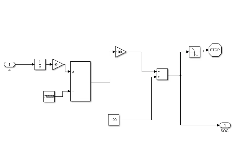
The Hit and stop blocks are used to stop the simulation when the SOC% decreases to 0.
The battery capacity is taken as 70000 Ah.
the initial SOC (t-1) = 100 %
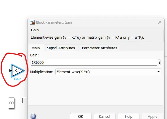
this gain converts the value of the A-sec into an hour.
The other gain block is used to convert the value in percentage.
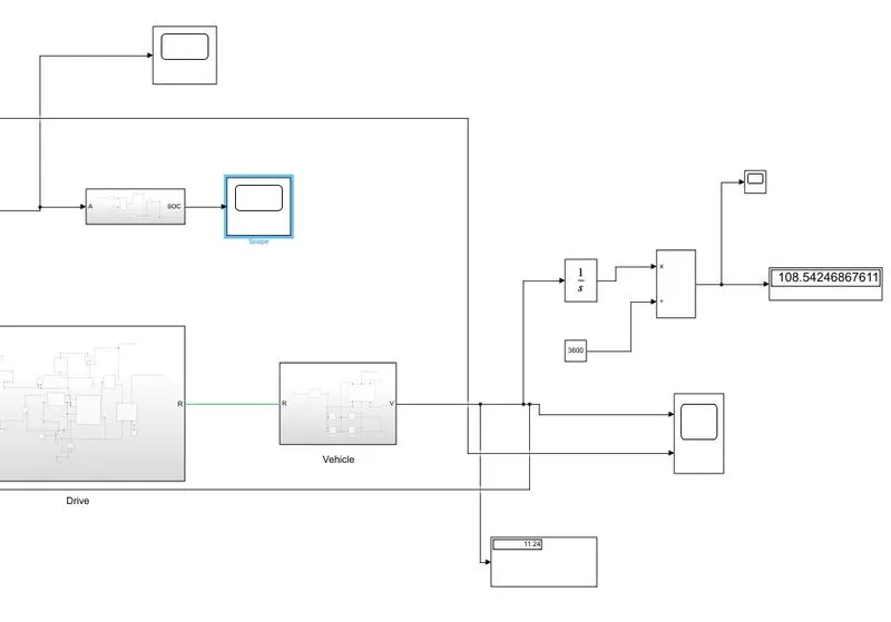
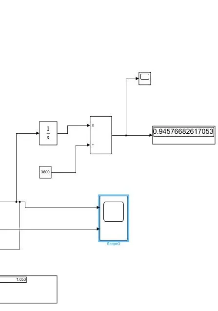
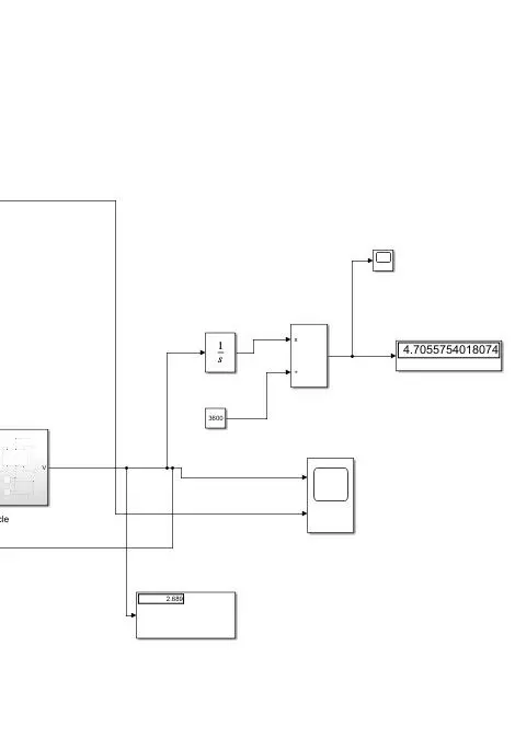
Distance calculation;
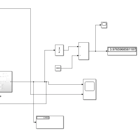
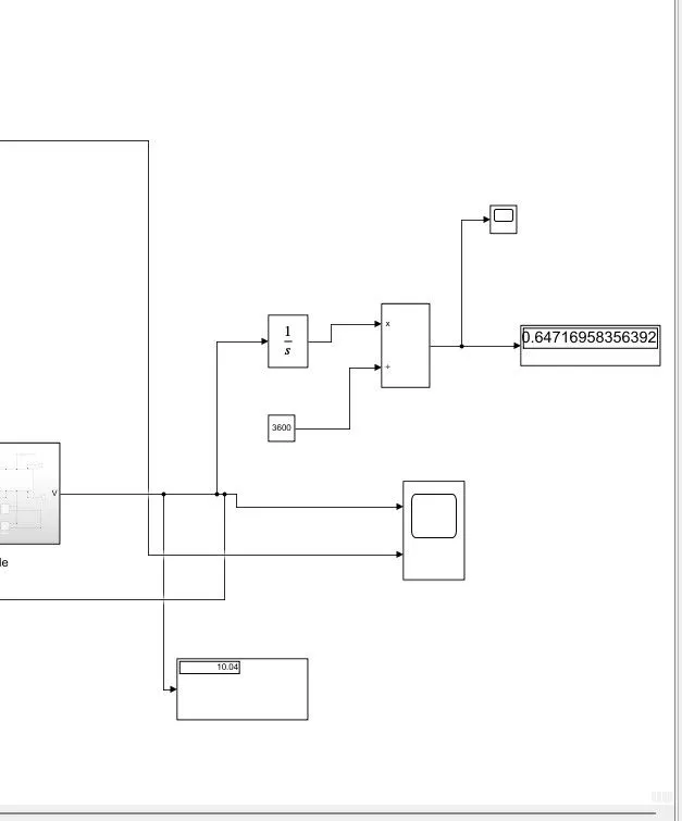
As we know the integration of the velocity gives the distance.
here the velocity of the vehicle is taken as the output and integrated by using the integration block w.r.t time.
Result:
The result is taken with no changes in the parameters which means the result shown below is the result which generates by the default value of the blocks :
vehicle mass = 1200kg
distance covered = 108km
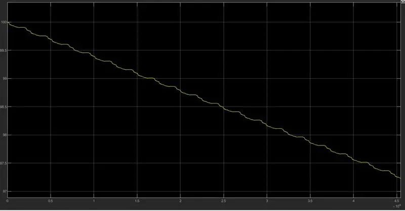
SOC% = 97.5%
Drive cycle source :
FTP75:
SOC :
Distance:
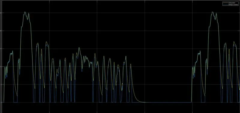
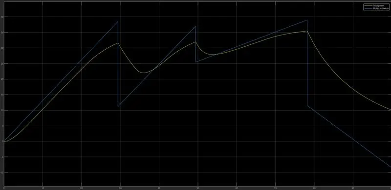
Drive cycle Vs actual cycle:
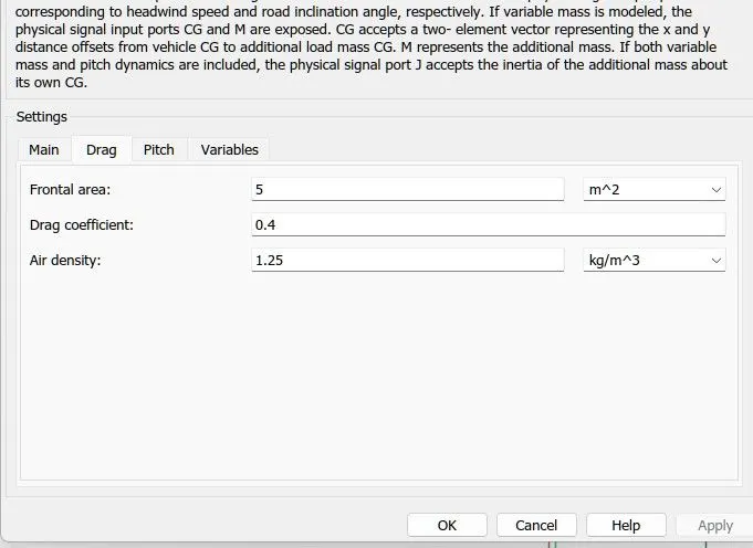
Parameters:
Signal builder:
Distance
Drive cycle:
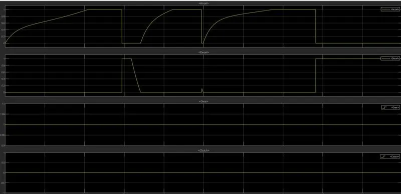
Acceleration and deceleration
From spreadsheet:
Distance :
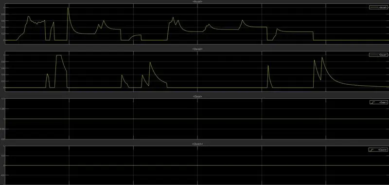
Acceleration and deceleration:
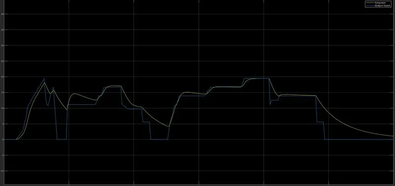
drive cycle
Iterations:
- Constraint parameters:
frontal area : 5 m^2
wind velocity = 0m/s
coefficient of drag : 0.4
Air density = 1.25 Kg/m^3
drive cycle = FTP-75

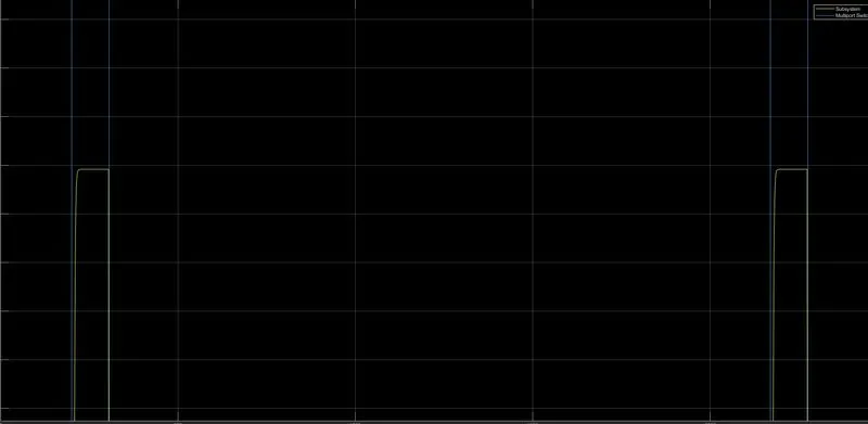
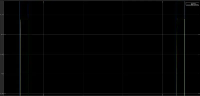
This iteration is made to observe the SOC, velocity of the vehicle, and the distance covered when the mass of the vehicle and the rated speed of motor (no-load speed/rated speed) is a change
- Iteration 2:

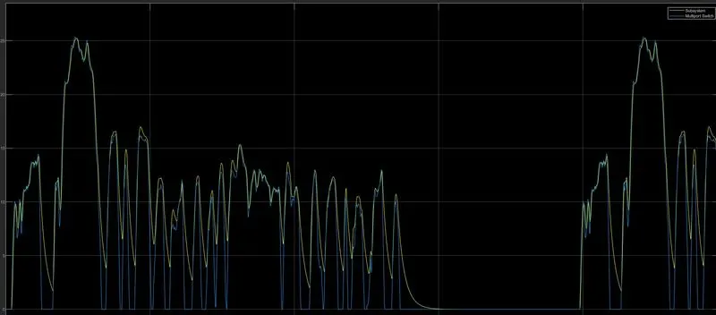
In this iteration, the frontal area, wind velocity, and the grade change after one another to observe the change in the deceleration and the velocity of the vehicle.
the deceleration is low in the hill-climbing situation. as compared to normal conditions.
Note: the iterations are made by changing some parameters and rest other parameters are remain unchanged.
Conclusion:
- The MATLAB model of an electric car that uses a battery and a DC motor using a power train block set and simscape is carried out.
- The number of iterations is made. and the results of the iteration are mentioned in the result.
- The model runs under different driving conditions.
- The model uses the PMDC motor.
- The model runs on the assumption which can be changed According to the requirement.