Final Project: Design of an Electric Vehicle
Create a MATLAB model of electric car which uses a battery and a DC motor. Choose suitable blocks from Powertrain block set. Prepare a report about your model including following:
Objectives:
1. System level configurations
2. Model parameters
3. Results
4. Conclusion
A. The Electric vehicle system level comfiguration part are mainly consists of transmission system, battery pack, motor , controller and vehicle body.
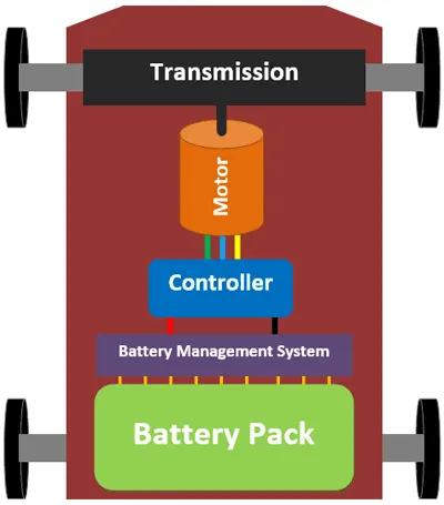
for the prediction of perfomance and better understanding by using of matlab and simulink liabrary a designer can achived
model digram and result analysis according to requirment .
that is low cost method of designing.
Battery Electric Vehicles
- A battery electric vehicle (BEV), pure electric vehicle, only-electric vehicle or all-electric vehicle is a type of electric vehicle (EV) that exclusively uses chemical energy stored in rechargeable battery packs, with no secondary source of propulsion.
- Battery Electric Vehicles (BEV) thus have no internal combustion engine, fuel cell, or fuel tank.
- Some of the broad categories of vehicles that come under this category are trucks, cars,buses, motorcycles, bicycles, forklift etc.
Electrical Vehicles – Better Energy Efficiency
- Internal Combustion engines will consume fuel even when the vehicle is stationary, whereas in electrical vehicles, the energy is not consumed when it is stationary.
- Electrical Vehicles ‘tank-to-wheels’ efficiency is about a factor of 3 higher than internal combustion engine vehicles
Advantages
- extremely quiet
- zero emissions when driving
- gearbox free
- easy and fun to drive
- cheap to run
- lower maintenance cost
- tax efficient
Electric vehicle model
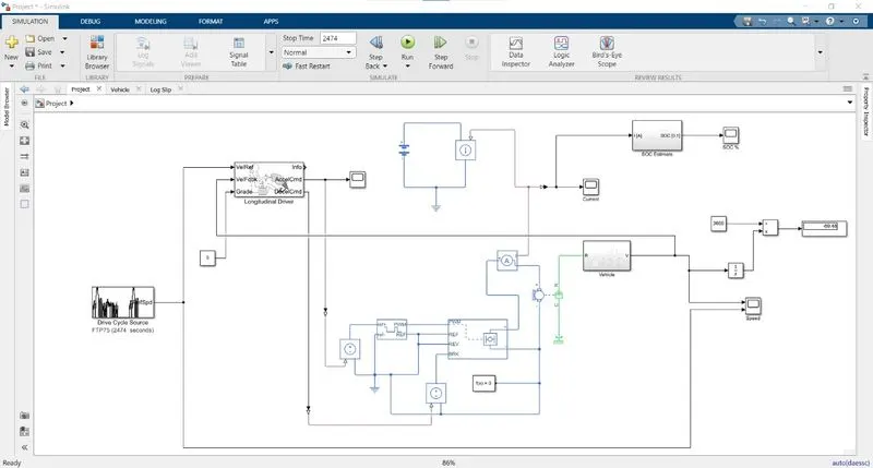
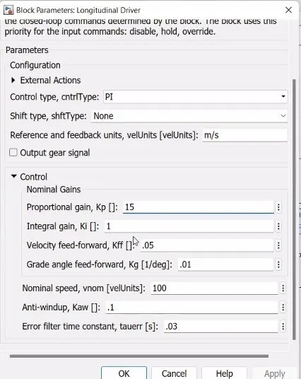
Logitudnal Driver: The Longitudinal Driver block implements a longitudinal speed-tracking controller. Based on reference and feedback velocities,
the block generates normalized acceleration and braking commands that can vary from 0 through 1.
Logitudnal Driver input that at what speed vehicle run and trcking the speed by controller .
Drive cycle Source : The block output is the specified vehicle longitudinal speed, which you can use to
Predict the engine torque and fuel consumption that a vehicle requires to achieve desired speed and acceleration for a given gear shift reference.
Vehicle Body:
here gear system for transmission and output of the gear system is connected to the wheel.
shaft of the motor is connected to the gearBox.
here after compliting the connection and installation of vehicle body , created a subsytem .
in above given model showing a vehicle block subsystem , after clicking that , new window will open and given below block model will open .
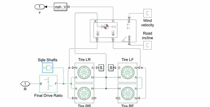
Vehicle Body consist of blocks given :
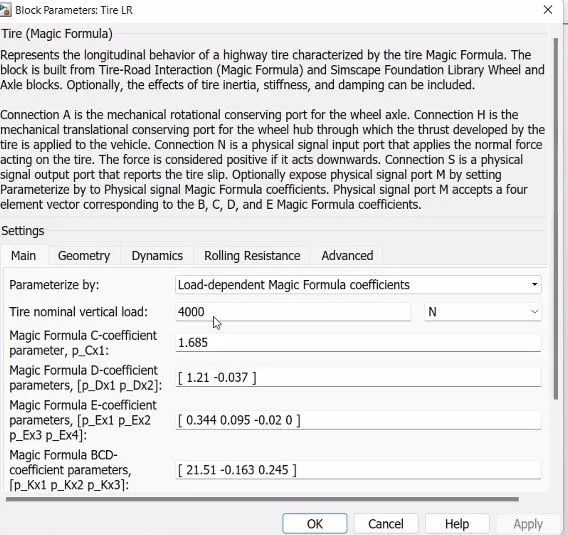
Magic Tyre: in 4 terminals are represent by N, S, A, H.
N = Normal Force
S= slip
A= Axel
H= Hub
The driveline connection line sequence of the model ends with the Vehicle Body block, which specifies the vehicle geometry, mass, aerodynamic drag, and initial velocity (zero).
This block generates the normal forces that the Tire blocks accept as vertical loads. Vehicle Body accepts the developed thrust force and motion at its horizontal motion translational port (H).
The vehicle body model also accepts a wind velocity (W) and a road incline (beta), both provided by physical constants.
DC Motor:
brush type dc motor , C is expresing casing and R is expresing Rotor. thier is electrical and mechanical combination .
blue is a electrical part , where will connect output of the power converter.
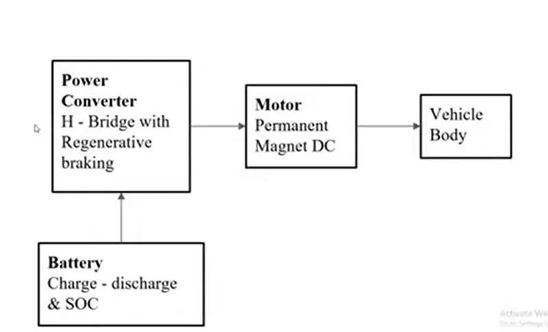
main thing is that how we are going to control the dc motor ? so using H-bridge .with PWM block.
in case of the actual designing of the vehicle it may be posible motor can be PM type or some other type .
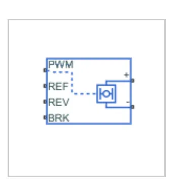
H-bridge : arrangement is generally used to reverse the polarity/direction of the motor, but can also be used to 'brake' the motor, where the motor comes to a sudden stop,
as the motor's terminals are shorted, or to let the motor 'free run' to a stop, as the motor is effectively disconnected from the circuit.
-
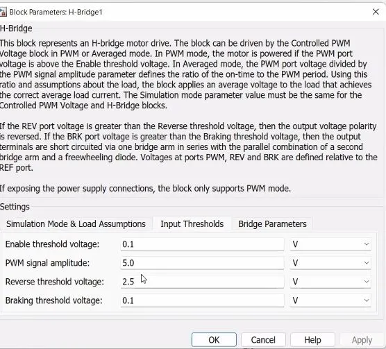
If it has a value less than the Enable threshold voltage parameter value, the block maintains the load circuit using one of the following three Freewheeling mode options:
The first and third options are sometimes referred to as synchronous operation.
The signal at the REV port determines the polarity of the output. If the value of the signal at the REV port is less than the value of the Reverse threshold voltage parameter,
the output has positive polarity; otherwise, it has negative polarity.
-
Averaged— This mode has two Load current characteristics options.
that is 4 terminal are available.positive terminal conencted to the positive of the motor and negative terminal to the negative of the motor .
when there is no power controller is connected between the wheels and the motor shaft, the transmission efficiency
will be 100% but the electric motor run 2 to 4 times faster that the vehicle wheels, so the design of motors with
low speeds is manufactured which leads to large heavy motors. Hor this resons, electronic power converters like h- bridge converters
provide the required power supply to the dc motor to generate the required amount of torque at the shaft to meet the tractive force demand at the wheels.
Controlled PWM Voltage block : The Controlled PWM Voltage block represents a pulse-width modulated (PWM) voltage source.
Electrical input ports — The block calculates the duty cycle based on the reference voltage across its ref+ and ref- ports.
0 and 1 are input as a acceleration and break input are connected to the break point of H-Bridge.
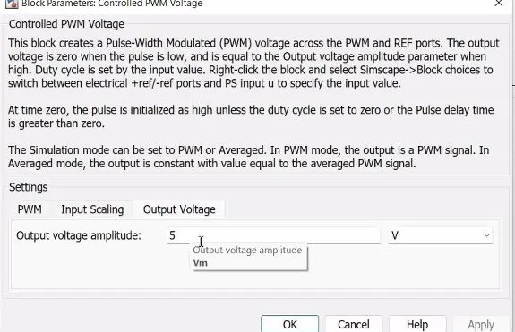
Parameters changed here from default are simulation mode is Averaged
Input Voltage for 100% duty cycle is 1 Output Voltage amplitude is 1 The remaining all are kept constant.
here initial state of Charge is 1.
Baterry:
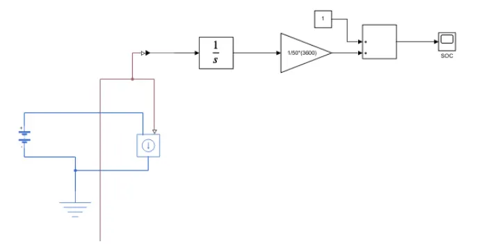
- The positive terminal of the battery is connected to the positive port of the controlled current source and the negative terminal is connected to the negative port if the
- controlled current source.
- The physical signal of the controlled current source is connected to a PS- simulink converter to conect to go block.
- connect integrater to the gain block such that ampere-hour is converted to ampere sec and connect it sum block with constant1
- Create Go Block name it as SOC.
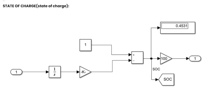
To measure the state charge of the battery . the integrator block is used to handle data tranfer and integrate the value
of the current signal with respect ti time then gain block is used in order to multiply divide the signal coming from
the integrating block. this block will divide a current signal with the ampere ratine battery which is 160(ah)*3600(sec).
Assuming the battery is always the battery is always fully charged i have added a constant block with a value of 1 representing 100%.
Solver Configraution :
Each physical network represented by a connected Simscape™ block diagram requires solver settings information for simulation.
The Solver Configuration block specifies the solver parameters that your model needs before you can begin simulation.
Each topologically distinct Simscape block diagram requires exactly one Solver Configuration block to be connected to it.
Gear System:
Geared devices can change the speed, torque, and direction of a power source.
The basic principle behind the operation of gears is analogous to the basic principle of levers. A gear may also be known informally as a cog.
The rotational speeds, and the torques, of two meshing gears differ in proportion to their diameters. The teeth on the two meshing gears all have the same shape.
Output of SOC :
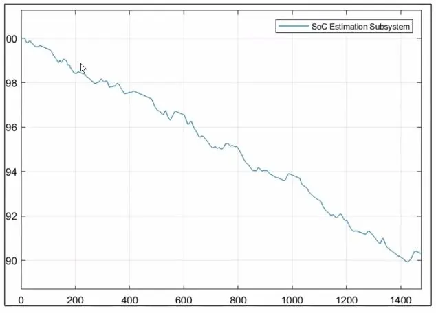
in this graph state of the battery decrease with time
in the SOC graph , the speed spikes show regenrative braking is considerd
Output of the vehicle :
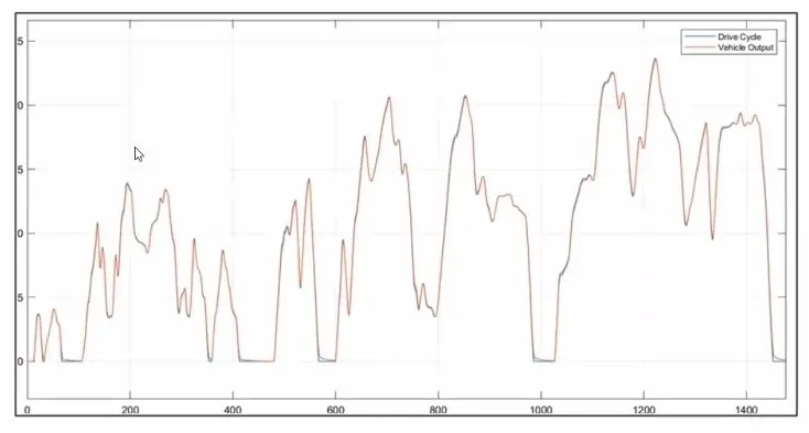
above graph shown Drive cycle and voltage output.
by the graph we can understand that the vehicle output is depend on the drive cycle.
Conclusion:
- Vehicle velocity — The speed increases less with each upshift for gears one, two, and three. The velocity decreases slightly before it starts to stabilize when the car is in fourth gear.
- we can understand that the vehicle output is depend on the drive cycle.