Final Project: Design of an Electric Vehicle
STUDENT OF ONLINE EV BATCH 16
I don't have powertrain blockset.
ANS :
Create a MATLAB model of electric car which uses a battery and a DC motor. Choose suitable blocks from Powertrain block set. Prepare a report about your model including following:
OBJECTIVES :
1. System level configurations
2. Model parameters
3. Results
4. Conclusion
Electric Vehicle :
- An Electric Vehicle is a vehicle that operates on an electric motor, instead of an internal combustion engine that generates power by burning a mix of fuel and gases.
- Electric vehicle is seen as a possible replacement for the current-generation automobile in near future to address environmental challenges.
COMPONENTS OF EV :
Components of EV are as follows :
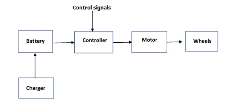
1. BATTERY :
- Electric vehicles use lithium-ion batteries of various design, similar to those used in cell phones and laptop computers, only on a much larger scale.
- Lithium-ion batteries have a high energy density and are less likely than other types of batteries to lose their charge when not being used.
- An EV’s battery capacity is expressed in terms of kilowatt-hours, which is abbreviated as kWh.
2. MOTOR CONTROLLER :
- The electric vehicle controller is the electronics package that operates between the batteries and the motor to control the electric vehicle's speed and acceleration much like a carburetor does in a gasoline-powered vehicle.
3. ELECTRIC MOTOR :
- In an electric car, the electric motor is just one part of a larger unit called the Powertrain.
- Here we also find the Power Electronic Controller (PEC), in charge of the electronics that control the motor’s power supply and battery charging, and the gear motor which adjusts the torque (turning force) and speed of rotation.
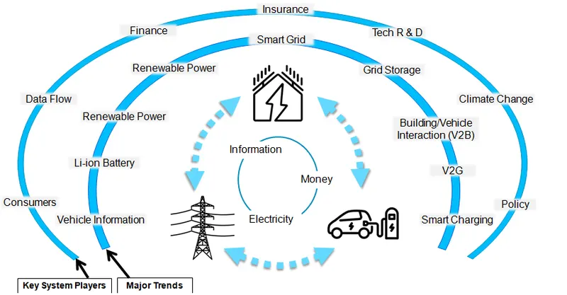
Ecosystem of EV :
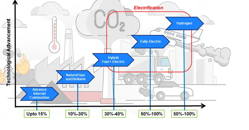
Carbon Emission :
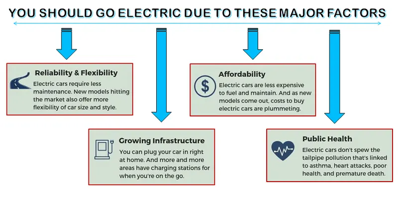
WHY EV TECHNOLOGY :
KEY PLAYERS OF EV :
PROCESS :
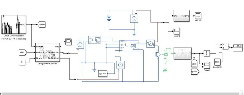
1. VEHICLE BODY SUBSYSTEM :
TIRES :
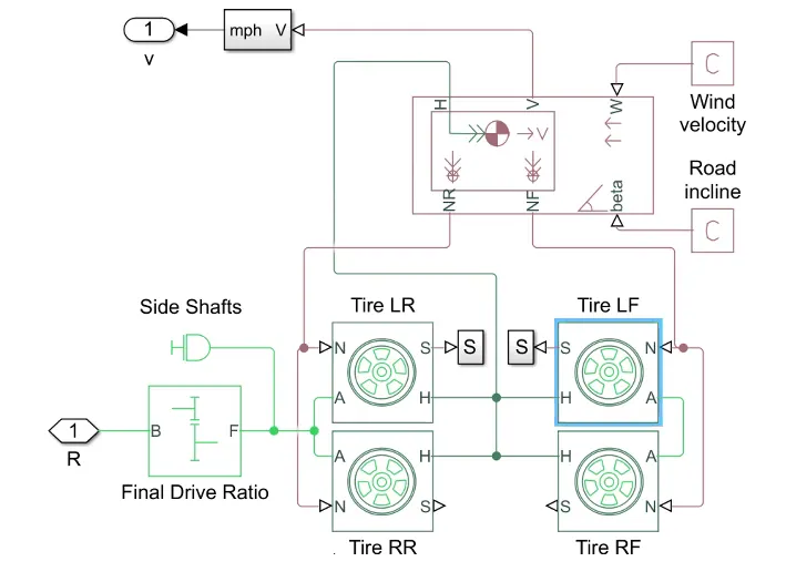
- The vehicle is assumed to be a front axle driven ( 4 wheels - 2 on each)
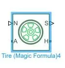
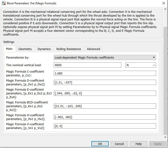
- The wheels are modelled using simple Tire (Magic Formula) simulink blocks.
- The N port of the tire corresponds to the normal reaction acting on it.
- The A port corresponds to Mechanical Energy Conversion port for the wheels axle.
- The H port corresponds to the Mechanical Translational Consering port for the wheel hub.
This 2 axle(4 wheel) assembly is connected the velocity boby as :
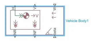
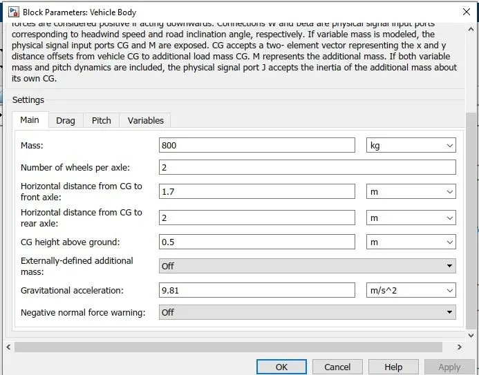
- This block basically represents a two-axle vehicle body in longitudinal motion.
- This block accounts for body mass, aerodynamic drag, road incline, road profile.
- The port H corresponds to mechanical translational conserving port.
- The port NF and NR corresponds to normal reaction forces.
- The port V corresponds to output translational velocity of the vehicle.
- The port W corresponds to headwind speed ( Direction opposite to that of vehicle).
INERTIA :

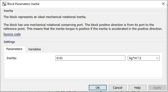
- The block represents an ideal mechanical rotational inertia.
- The block has one or two mechanical rotational conserving ports.
- The difference is purely graphical, as the ports are rigidly linked.
- The block positive direction is from its port to the reference point.
- This means that the inertia torque is positive if the inertia is accelerated in the positive direction.
VEHICLE SUBSYSTEM :
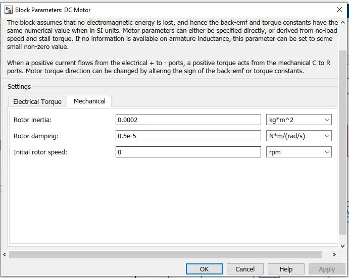
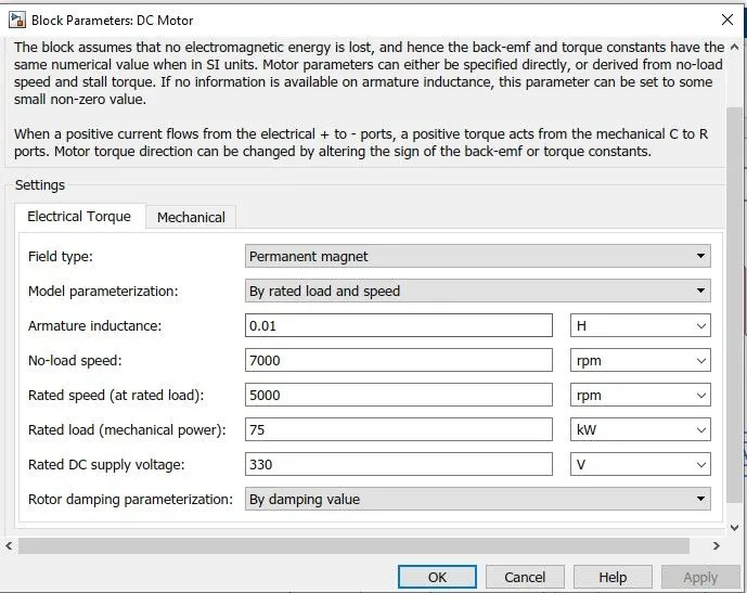
2. DC MOTOR :
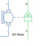
- This block represents the electrical and torque characteristics of a DC motor.
- The block assumes that no electromagnetic energy is lost, and hence the back-emf and torque constants have the same numerical value when in SI units.
- Motor parameters can either be specified directly, or derived from no-load speed and stall torque. If no information is available on armature inductance, this parameter can be set to some small non-zero value.
- When a positive current flows from the electrical + to - ports, a positive torque acts from the mechanical C to R ports. Motor torque direction can be changed by altering the sign of the back-emf or torque constants.
3. MOTOR CONTROLLER :
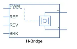
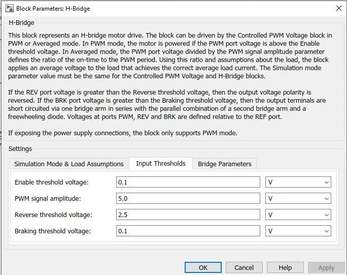
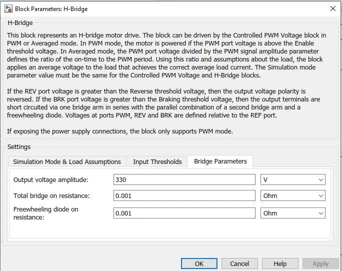
- This block represents an H-bridge motor drive.
- The block can be driven by the Controlled PWM Voltage block in PWM or Averaged mode.
- In PWM mode, the motor is powered if the PWM port voltage is above the Enable threshold voltage.
- In Averaged mode, the PWM port voltage divided by the PWM signal amplitude parameter defines the ratio of the on-time to the PWM period.
- Using this ratio and assumptions about the load, the block applies an average voltage to the load that achieves the correct average load current.
- The Simulation mode parameter value must be the same for the Controlled PWM Voltage and H-Bridge blocks.
4. LONGITUDINAL DRIVER :
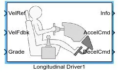
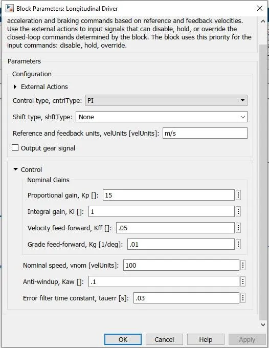
- It is parametric longitudinal tracking controller.
- It is used for generating normalized Acceleration and Braking commands.
- Velref port corresponds to velocity reference.
- Velfdbk port corresponds to velocity feedback.
- Garde port corresponds to Grade angle.
- Info port corresponds to output for the bus signal.
- AccelCmd port corresponds to Acceleration.
- DccelCmd port corresponds to Deceleration.
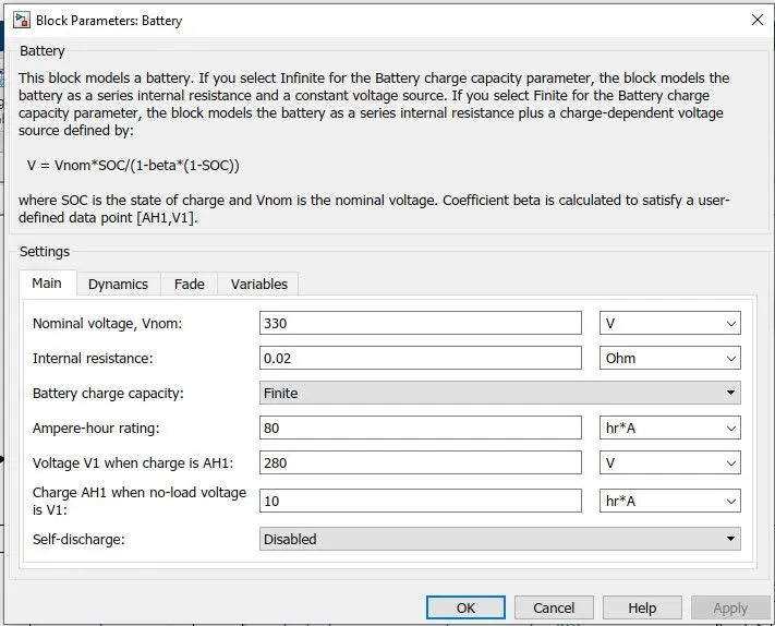
5. BATTERY :
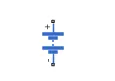
- This block models a battery.
- If you select Infinite for the Battery charge capacity parameter, the block models the battery as a series internal resistance and a constant voltage source.
- If you select Finite for the Battery charge capacity parameter, the block models the battery as a series internal resistance plus a charge-dependent voltage source defined by:
- V = Vnom*SOC/(1-beta*(1-SOC))
- where SOC is the state of charge and Vnom is the nominal voltage.
- Coefficient beta is calculated to satisfy a user-defined data point [AH1,V1].
6. REFERENCE VELOCITY( DRIVE CYCLE) :
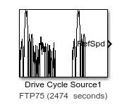
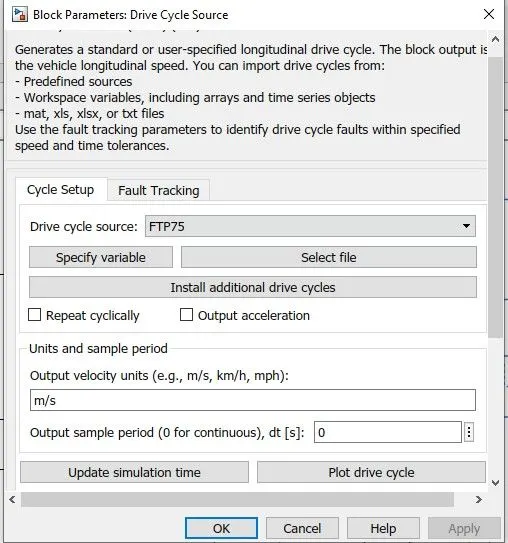
- The Drive cycle source block is used to provide the reference speed for the simulation.
- It generates a standard or user - specified longitudinal drive cycle.
7. BATTERY STATE OF CHARGE :
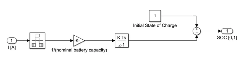
- A small subsystem is created to calculate the state of charge of the battery.
- This subsystem takes the battery current as the input.
- The essential process to calculate the SOC is by subtracting the charge from the rated capacity of the battery.
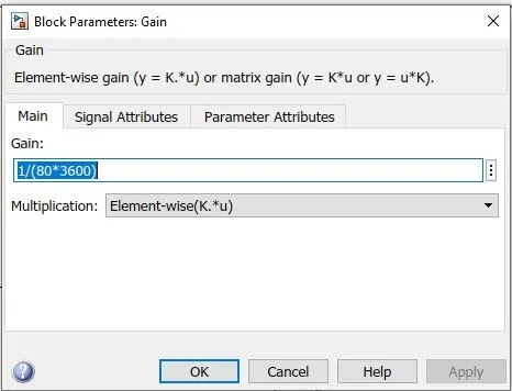
GAIN :

-
Element-wise gain (y = K.*u) or matrix gain (y = K*u or y = u*K).
RATE TRANSITION :
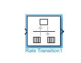
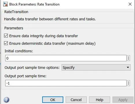
- Handle data transfer between different rates and tasks.
SIMULINK MODEL :
SIMULATION RESULTS :
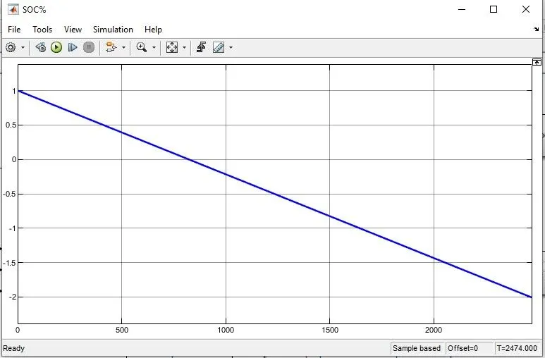
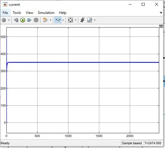
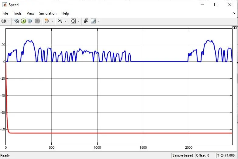
CONCLUSION :
The Simulink Model has been succesfully run for FTP75(2474 seconds) drive cycle and the results has been analyzed properly.