Final Project: Design of an Electric Vehicle
Note : i am part of live ev batch 13
Theory :
- Electric vehicle compared to classic internal combustion engine vehicles , are fairly simple and easy to operate.
- An Ev ( electric vehicle) is a vehicle that uses one or more electric motors or traction motor for propulsion .
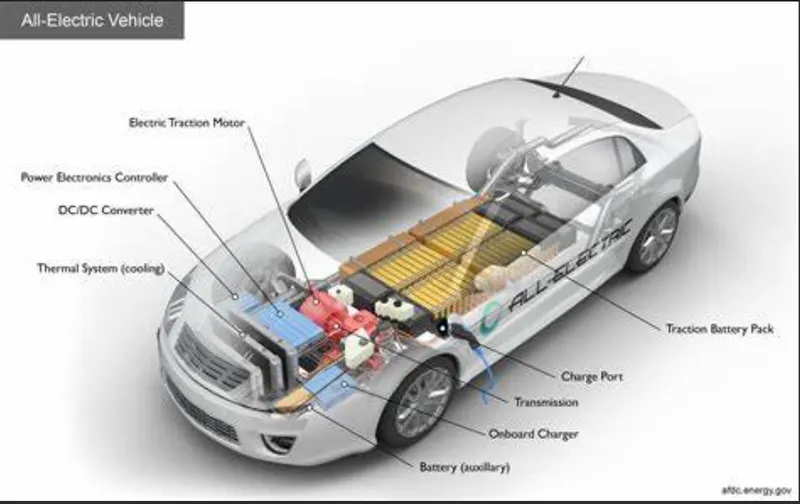
Components of an EV :
1 ) Battery:
- The battery of an electric vehicle can be charge through the use of ordinary grid electricity at a specialized power station.
- But aside from the conventional lithium - ion battery technology , they ae also major battery technology which can be used for electric car .
2 ) Motor Controller :
- The motor controller of an electric car administers its complete operation and the distribution of its power at any given movement .
- Its acts as a floodgate between the motor and batteries .
- It helps monitor and regulates all key performance indications such as the vehicle's operator , motor , battery , and accelerator pedal .
- It has a microprocessor which can limit or redirect current .
- It is used to either improve the mechanical performance of the car or suit the operator's driving style .
- There are also more refined controllers which are capable of greater accuracy and thus, higher efficiency .
3 ) Electric Motor :
- Unlike a gasoline engine with lots of moving parts , a motor only has one moving part .
- This makes it a very reliable source of motive power .
- Choosing an electric motor depends on the car's system voltage .
- They can be structured to use either AC or DC current .
- AC motors are less expensive and lighter compared to DC motors .
- They tend to suffer from less mechanical wear and tear .
- However , AC technology requires a more refined or sophisticated motor controller .
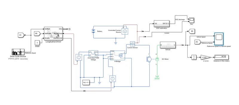
B ) modeling of an electric vehicle :
1 ) vehicle subsystem:
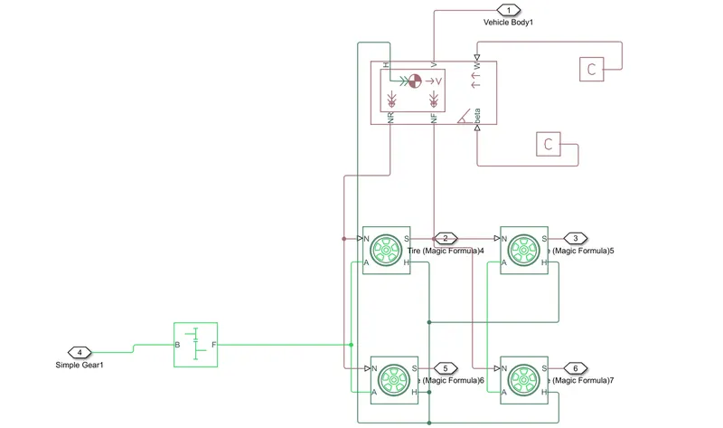
- Vehicle sub- system consist of :
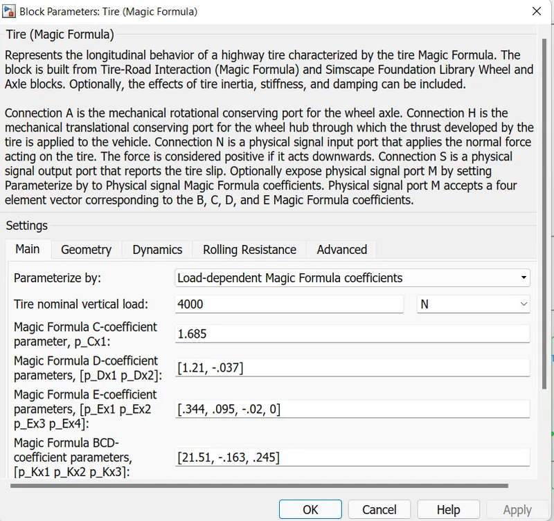
1 ) Magic tire (4) in which two for front axle and two for rear axle .
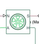
- Magic tire has 4 ports
- N port of the tire correspond to normal reaction force.
- A port correspond to mechanical rotational conversing port for yhe wheel axle .
- H is the mechanical translational conserving port for the wheel hub .
- connection S is physical signal output port that reports the tire slips .
- input for tire are as follow.
2 ) Vehicle body :
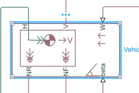
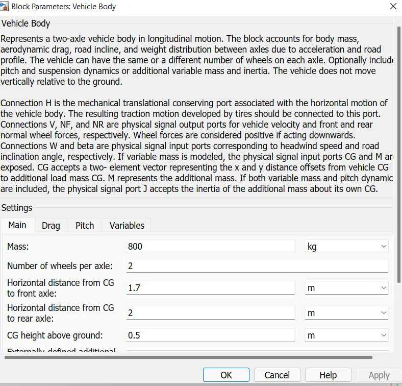
- This block represent two axle vehicle body in longitudinal motion .
- the block account for aerodynamic drag , road inclination , and weight distribution between axles due to acceleration and road profile .
- Connection H is mechanical translational conserving port.
- Connection V, NF and NR are physical signal output ports for vehicle velocity and frontal and rear normal wheel forces , respectively .
- inputs of the block are shown below .
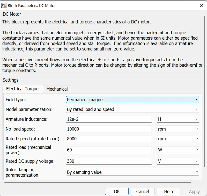
2) D-c Motor :
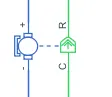
- This block represent the electric and toque charecteristic of a DC motor .
- When positive current flows from the electrical ports , a positive torque acts from the mechanical C to R port .
- Motor torque direction can be changed by altering the sign of the back - emf of the torque constant .
3 ) H bridge :
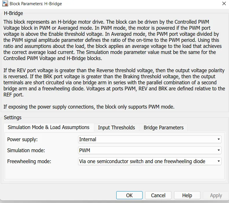
- This block represent an H bridge motor drive .
- The block can be driven by controller pwm voltage block or Average mode .
- In avg mode , the pmw port voltage divided by the PWM signal amplitude parameter defined the ratio of the on -time to the pwm period.
4 ) Controlled PWM voltage :
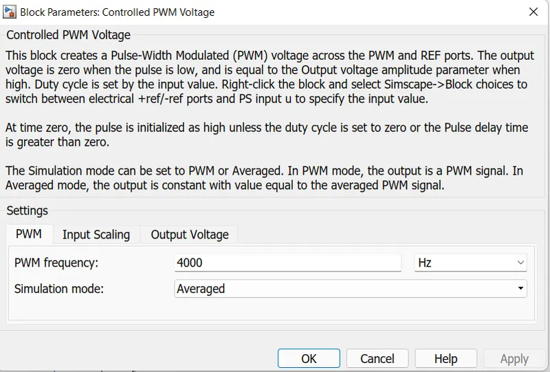
- The block create a pulse - width modulation (PWM) voltage acros the PWM and REF ports .
- The output oltage is zero when the pulse is loe and is equal to the output amplitude parameter when high.
- Duty cycle is set by input values .
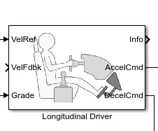
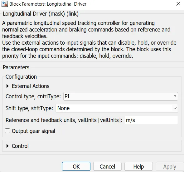
5 ) Longitudinal driver :
- It is a parametric longitudinal speed tracking controller for generating normalized acceleration and braking commands based on reference and feedback velocities.
6) Drive cycle:
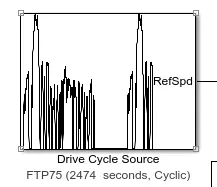
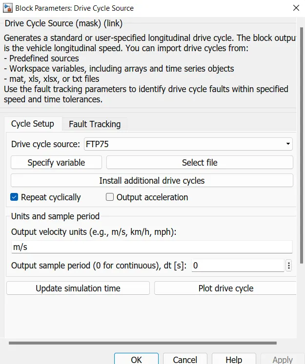
- it generate a standard or user - specified longitdinal drive cycle .
- The block output is vehicle longitudinal speed .
- we can import drive cycle in following ways :
- predefined sourse
- workspace variable
7 ) Battery sub system :
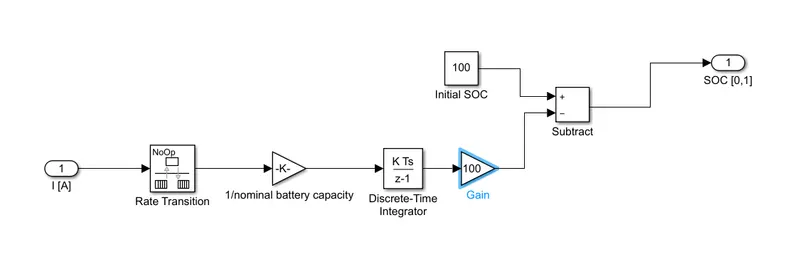
- Battery subsystem is created to find SOC .
OUTPUTS :'
1 )
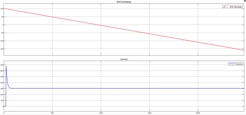
- The above graph shows the SOC of the battery.
- In this condition battery is fully discharge .
- It will cover less distance than drive cycle.
- It also shows the output of current .
2)
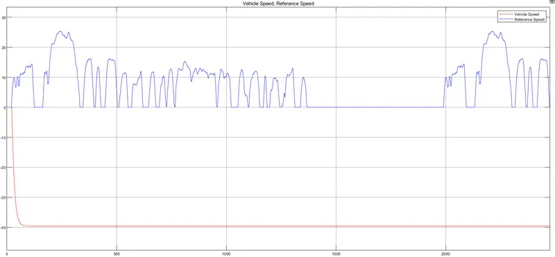
- The above graph shows the velocity of drive cycle and velocity of vehicle.
Below is the link of model,
https://drive.google.com/file/d/1CIH3g76fWVcu6yJNpAQCDu5dAS6ccuUQ/view?usp=sharing
Conclusion :
- Electric vehicle model is made in simulink .
- outputs are obtain from graph.