Final Project: Design of an Electric Vehicle
1)System level configurations
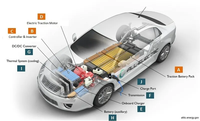
How Does An Electric Car Work?
When the car pedal is depressed, then:
Controller takes and regulates electrical energy from batteries and inverters With the controller set, the inverter then sends a certain amount of electrical energy to the motor Electric motor converts electrical energy into mechanical energy (rotation)Rotation of the motor rotor rotates the transmission so the wheels turn and then the car moves.
Components of Electric Vehicle
Main Components of Electrical Vehicle
Traction Battery Pack
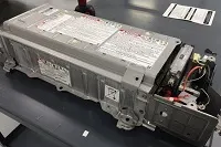
The function of the battery in an electric car is direct-current electricity (DC). If it gets a signal from the controller, the battery will flow DC electrical energy to the inverter to then be used to drive the motor. The battery used is a rechargeable battery that is arranged to form what is called a traction battery pack.
Power Inverter
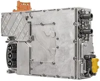
The inverter functions to change the DC on the battery into an AC and then this AC is used by an electric motor. Snd the inverter on an electric car also has a function to change the AC when regenerative braking to DC current and then used to recharge the battery. The type of inverter used in some electric car models is the bi-directional inverter category.
Controller
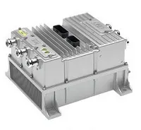
the controller is as a regulator of electrical energy from batteries and inverters that will be distributed to motors. While the controller itself gets the main input from the pedal. This pedal setting will determine the frequency variation or voltage variation that will enter the motor, and at the same time determine the car’s speed
Electric Traction Motor
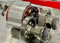
As the controller provides electrical power from the traction battery, the traction motors will work turning the transmission and wheels. Some hybrid electric cars use a type of generator-motor that performs the functions of propulsion and regeneration.
Other Electric Car Components
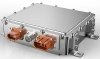
Charger is a battery charging device. Chargers get electricity from outside sources, such as the utility grid or solar power plants. AC electricity is converted into DC electricity and then stored in the battery. There are 2 types of electric car chargers:On-board charger/Off-board charger
Transmission : The transmission transfers mechanical power from the electric traction motor.
DC/DC Converter This one of electric car parts that to converts higher-voltage DC power from the traction battery pack to the lower-voltage DC power needed to run vehicle accessories and recharge the auxiliary battery.
Auxiliary Battery : In an electric drive vehicle, the auxiliary battery provides electricity to power vehicle accessories.
Thermal System – Cooling : This system maintains a proper operating temperature range of the engine, electric motor, power electronics, and other components.
PLug-in Port/ Charge Port : The charge port allows the vehicle to connect to an external power supply in order to charge the traction battery pack.
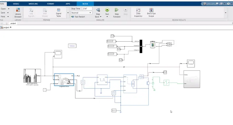
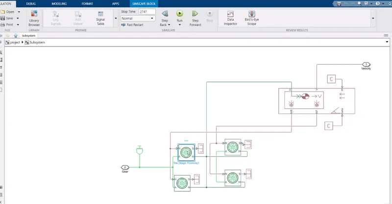
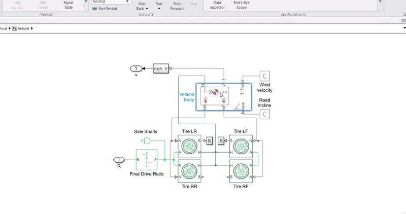
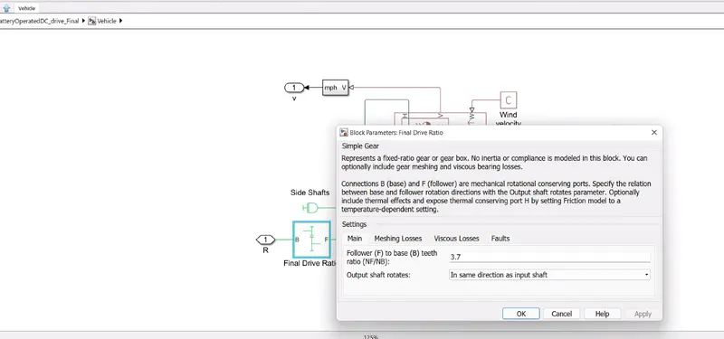
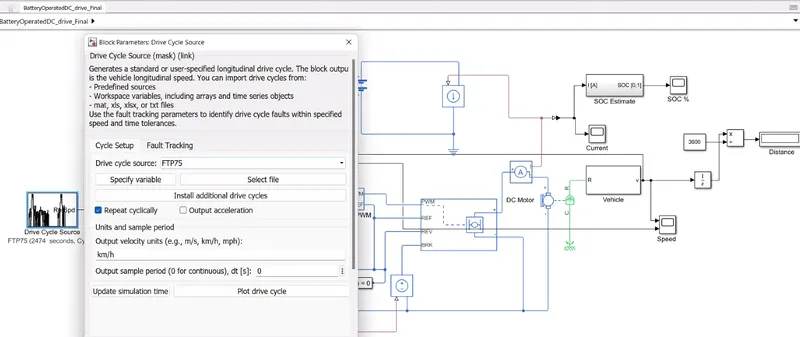
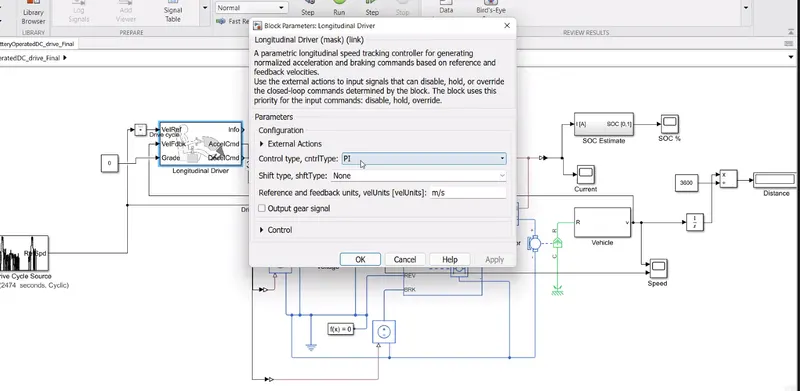
2. Model parameters
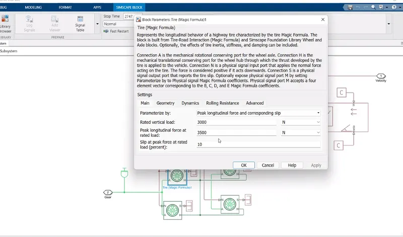
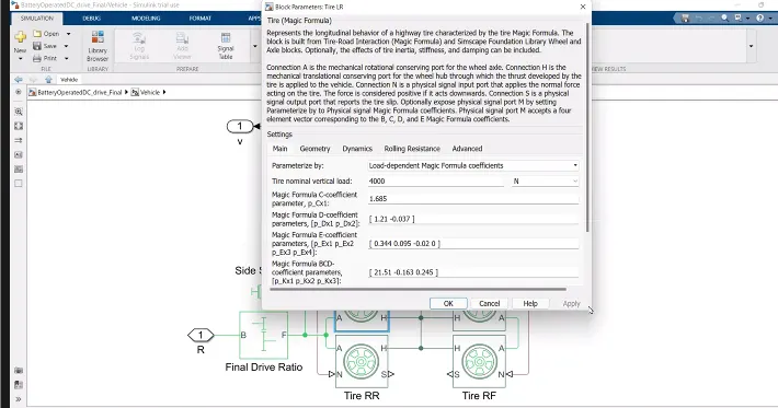
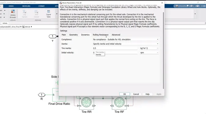
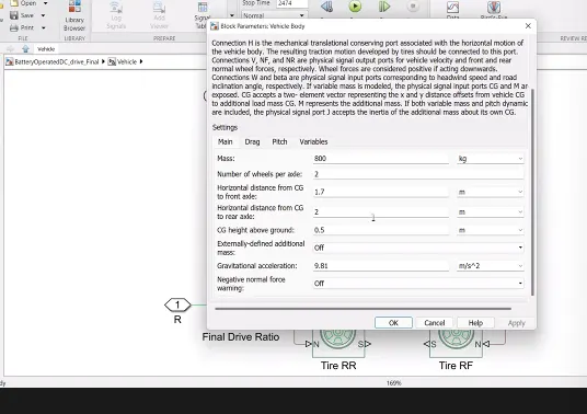
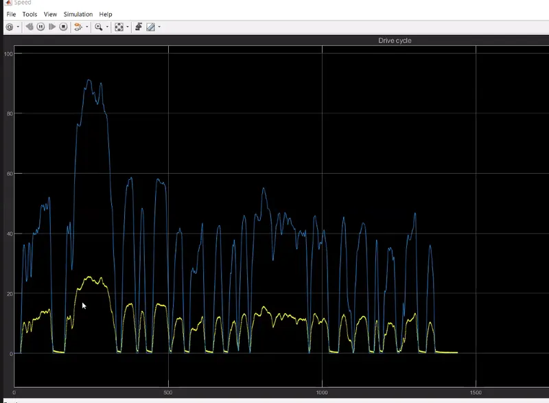
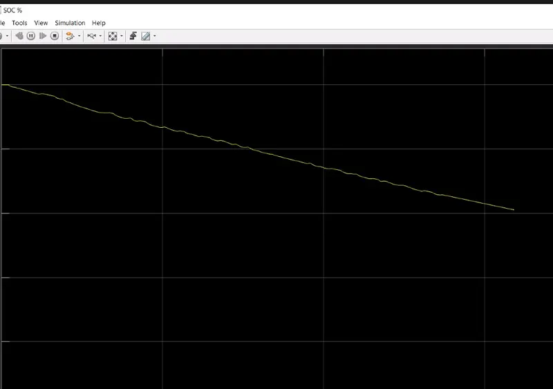
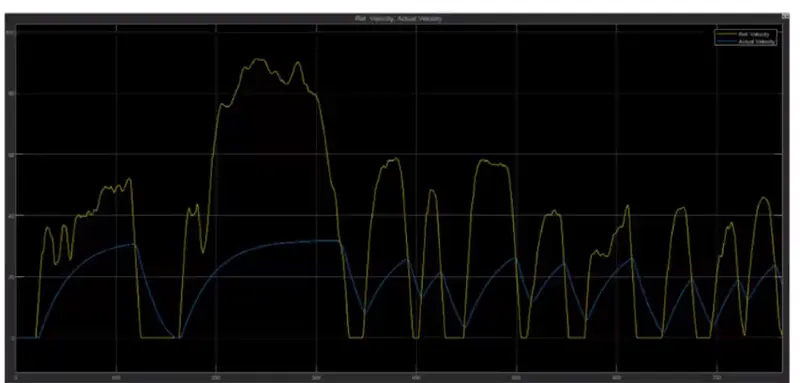
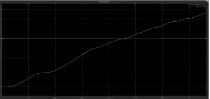
3. Results
4. Conclusion