Final Project: Design of an Electric Vehicle
Q: Create a MATLAB model of electric car which uses a battery and a DC motor. Choose suitable blocks from Powertrain block set. Prepare a report about your model including following:
Objectives:
1. System level configurations
2. Model parameters
3. Results
4. Conclusion
A: To create a MATLAB model of electric car which uses a battery and a DC motor.
Electric Car:
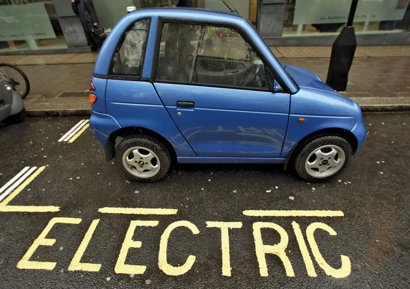
An Electric Car (EV) is essentially an automatic vehicle with an electric motor powering it. A fully electric car does not run on or have a petrol or diesel engine. With an Electric Car, when you place the car in 'drive' mode, the vehicle accelerates just like an automatic vehicle. Electric cars function by plugging into a charge point and taking electricity from the grid. They store the electricity in rechargeable batteries that power an electric motor, which turns the wheels. Electric cars accelerate faster than vehicles with traditional fuel engines so they feel lighter to drive.
Main components:
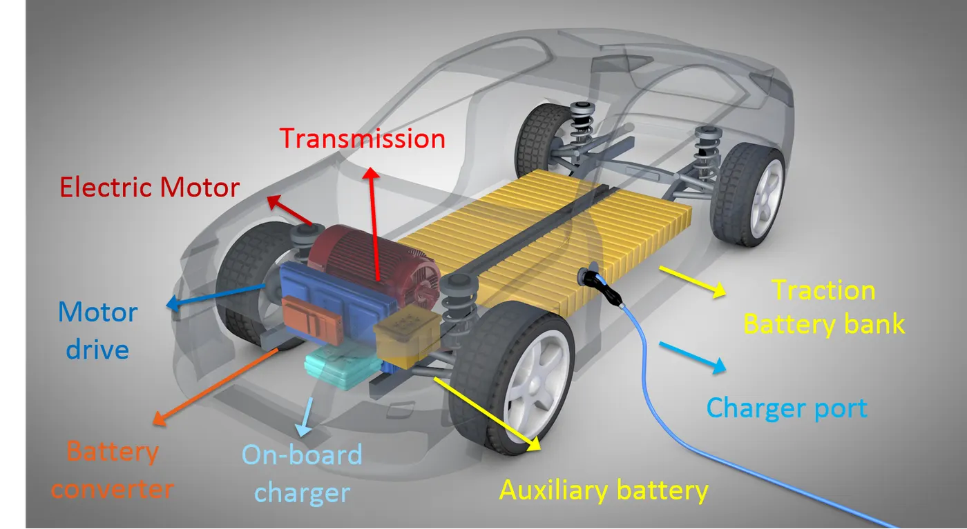
Electric vehicles are becoming a part of our modern life because of its efficient performance characteristics and due to its tremendous fuel economy, eco friendly nature and smooth driving feel. EV's are a lot different from internal combustion engine in its operating mechanism, maintanance, usage etc.
Lets discuss about the major components of Electric car;
- Electric motor: The component of an electric vehicle that transforms the electrical energy from the battery into rotation that can be used to move the vehicle. There are many types of electrical motors and, even though the basic technology hasn't changed over the last 100yrs or so, there have been many improvements in motor design and efficiency.
- Battery Management System: The BMS manages the electrical current flow in and out of the battery to protect the battery and extend its life. Every EV is going to have a BMS that is designed specifically for the battery in the car. Thus, modifying the battery or adding a battery could prove to be quite difficult if the BMS is not also modified to compensate.
- An onboard battery charger: Most EVs have a battery charger built into the car for level 1 or level 2 charging. This is AC charging, not DC fast charging. The charger is there to limit the total amount of power going into the battery to avoid damage to the battery or the electrical circuit the charger is plugged into.
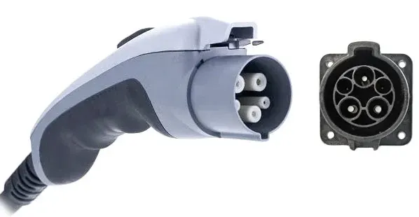
- Charging port: Much like the access port for the gas tank in an internal combustion engine car, the charge port is the location where energy enters the car. There are 3 main EV chargng speed slow, fast and rapid. In case of slow its typically rated upto 3KW and is often used to charge overnight or at a workplace. Its charging time is 8-10 hours. For fast charging its typically rated at either 7KW or 22KW. It tendsto be installed in car parking, supermarkets etc. Its charging time is 3-4 hours. For rapid charging its typically rated from 43KW. Its only compatible with EV's that have rapid charging capability. Charging time is 30-60 minutes only.
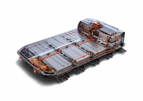
- A battery pack: This is the energy reservoir that contains the energy the car will use to drive, operate the heating and cooling, and run all of the other lights and accessories. Batteries usually use direct current electricity that must be converted to AC, or alternating current, before being used in the electric motor. Sometimes, you will find direct current motors, but these are not common in mass produced electric vehicles. DC charging is faster because it charges the batteries directly.
- A power inverter: When an EV has AC motors, the energy from the battery must be converted in order to be used. The inverter also operates when the car is using regenerative braking converting the alternating current generated by the electric motors into direct current to be stored in the battery.
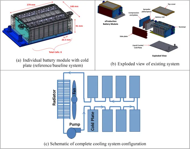
- A cooling/heating system: If equipped, a thermal management system can extend the life of the battery pack. Cooling it while fast charging and on hot days, and even warming it up on cold days or to prepare for fast charging. The TMS works with the BMS to create optimal battery conditions.
- Electrically driven accessories: Unlike in a gas or diesel vehicle using accessory belts, the air conditioning, power steering, and other components us electricity from the battery pack to operate. The lights, radio, and other components typically use traditional 12 volt direct current.
Block diagram representation:
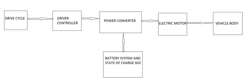
The block diagram shown above is related to the Simulink model created. Here as seen from the block diagram an input drive cycle is provided to the driver controller where it can be any drive cycle source like FTP drive cycle, drive cycle made using a signal builder, slider gain or it can be uploaded from spreadsheet too. There will be a longitudinal driver in which the reference velocity is inputted and feedback velocity is taken out and both the velocities are compared. The drive controller or longitudinal driver controlls the acceleration abd deceleration of vehicle. Power converter consists of Controlled PWM converter followed by an H-bridge with regenerative braking. H-bridge is used to drive the load here it is the dc motor. The battery system block indicates the charging and discharging condition and the % of SOC left or SOC variation with respect to the drive cycle. The motor block and battery system is connected to the power converter block which controlls and converts the electrocal energy. Here we are using a permanent magnet brushed dc motor. The vehicle body consits of mechanical components like simple gear system, wheels and thier connections.
MATLAB modeling of Electric Car:
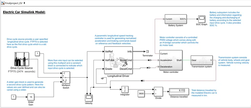
Here the electric car model is developed by using the powertrain blockset. Powertrain blockset mainly consists of regenerative braking control, motor torque and power management control. The following figure shows the Simulink model of an electric car.
Lets see in detail about each block:
Drive cycle input:
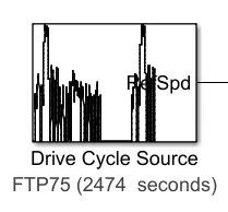
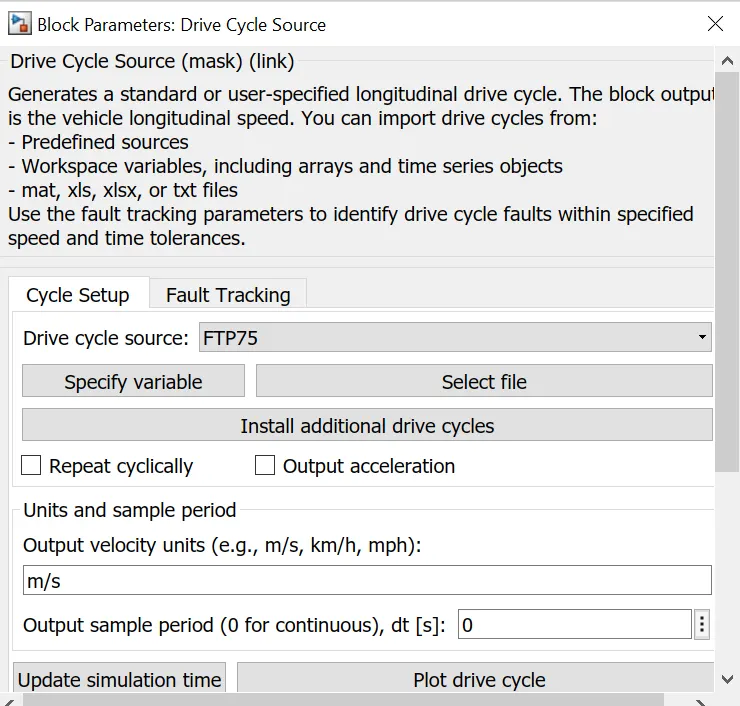
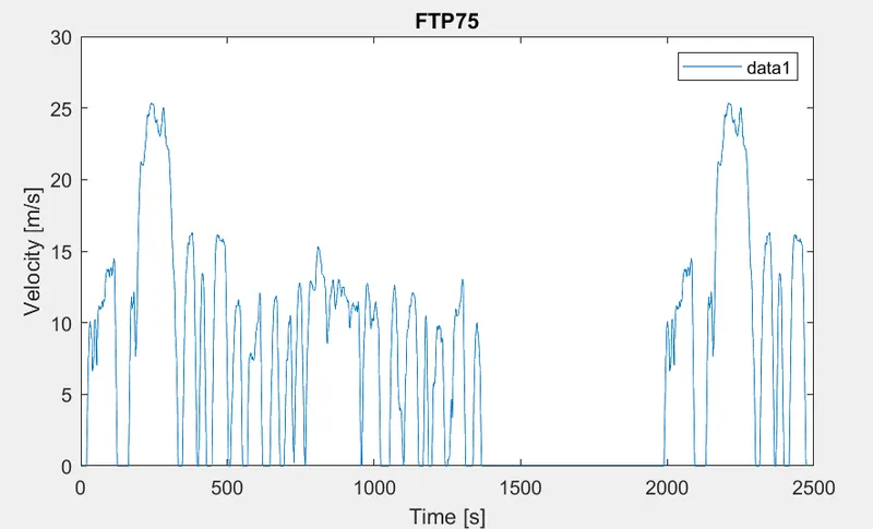
Adrive cycle gives constant velocity computation. It is defined as the variation in speed with respect to time. It is mainly developed for the practical test of emissions. It is more realistic case of better modeling of energy and range of battery. Drive cycle source provide a user specified longitudinal drive cycle. FTP75 is selected here as the first drive cycle which is a standard drive cycle. The simulation stop time is given as 2474 seconds.
These are the parameter values for the given block:
Plot of input FTP75 drive cycle :
Slider Gain block:
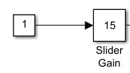
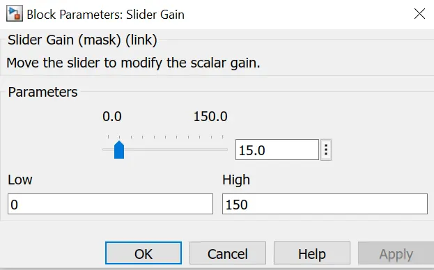
For a running or changing input slider gain block can be used. It produces various rpm values. Here we can set a low value and a high value. Then while running the simulation change the value between low and high using the slider bar. There will be output only if the slider gain block is connected to a constant block with 1 value otherwise result will be zero.
Multiport Switch:
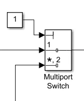
A multiport switch is used in cases where there are more than one inputs available. Here I have selected 2 input drive cycles so we need a multiport switch to keep desired drive cycle as input at each time. A constant block is connected tp the multiport in which we need to specify the selected or required drive cycle. Here if it is 1 in constant block then first drive cycle which is FTP will activate and 2 for slidergain.
Longitudinal Driver:
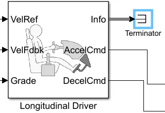
A longitudinal driver is a simulated driving environment where whatever the velocity input is, they will be followed by the vehicle. It act in such a way that the difference between the 2 inputs (actual speed from the car and the reference speed from input drive cycle source) is minimized. It is clear from the block given below that there will be a reference velocity, feedback velocity, a grade option which is grounded or provided zero value to terminate it. The other end consists of an acceleration command to drive the car, a deceleration command to give braking command when needed and a info part which is also not required thus terminated using a terminator block.
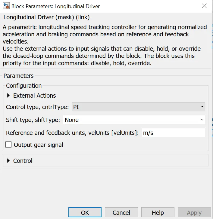
These are the parameter values for the given block: Here Proportional Integral controllers are selected as the controller for minimizing the error. PI controllers are efficient and good in performance.
Motor controller subsystem:
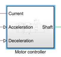
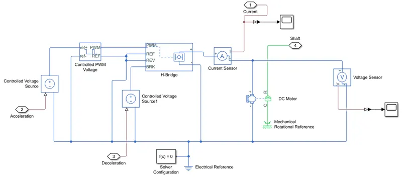
The subsystem consists of the following model as shown below. It controls the motor action and is connected in between the vehicle body and longitudinal block and is also connected with the battery. It controls the speed of motor and control the charging and discharging of motor according to the motoring and braking option.
Detailed subsystem:
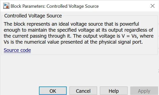
Controlled voltage source:
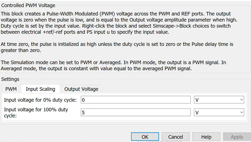
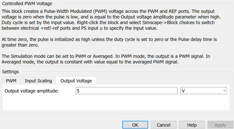
Controlled PWM voltage:
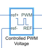
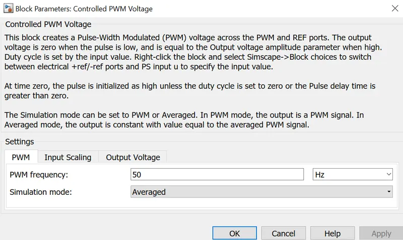
It represents Pulse Width Modulatedvoltage source. The block has 2 modeling variants for the simulation like PWM and averaged. To reduce simulation run time here it is selected as averaged.The block calculates the duty cycle based on the reference voltage across its positive reference and negetive reference ports. This modeling is default.
These are the parameter values for the given block:
H- Bridge:
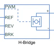
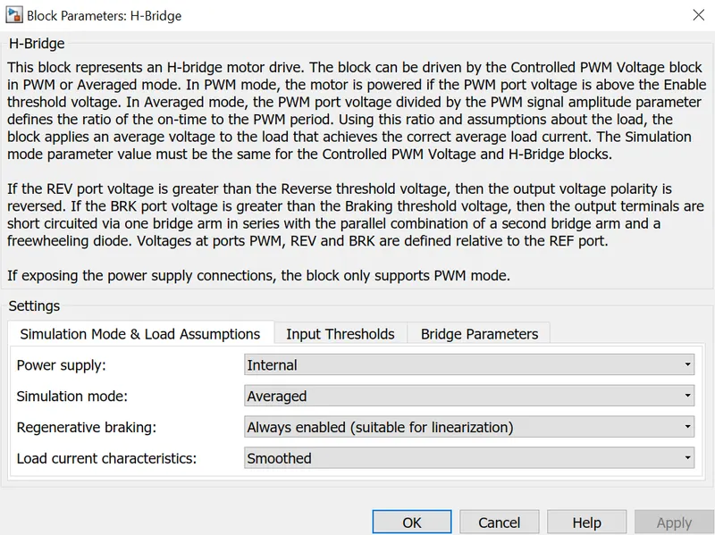
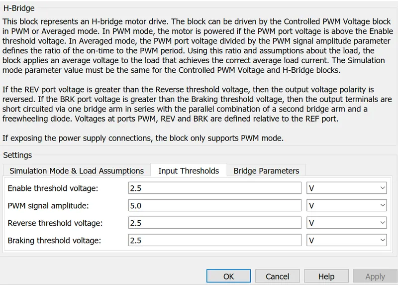
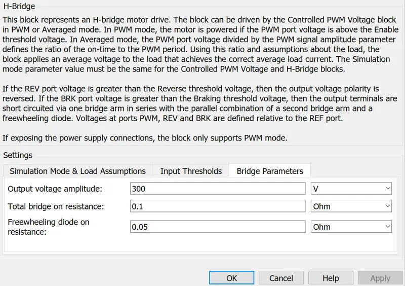
H bridge block looks like an H alphabet. It is usually connected along with the PWM voltage controller block. It is mainly used to drive a particular load. Here the load is dc motor drive. Here also the simulation mode is set as averaged as same as the pwm voltage controller block. This applies the average the average of the demanded PWM voltage to the motor. Braking mode is involved when the voltage presented in the BRKport larger than the braking threshold voltage. PWM and ref ports are connected to respective ports of controlled pwm voltage block. REV is connected to REF port and grounded together. The positive and negetive terminal connected to the dc motor along with a current sensor.
These are the parameter values for the given block:
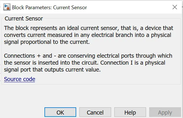
Current sensor: Used to sense the current across the connected terminals. It converts the current measured in any electrical branch into a physical signal propotional to the current.
DC Motor :
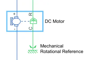
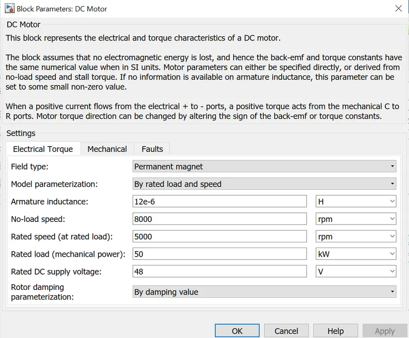
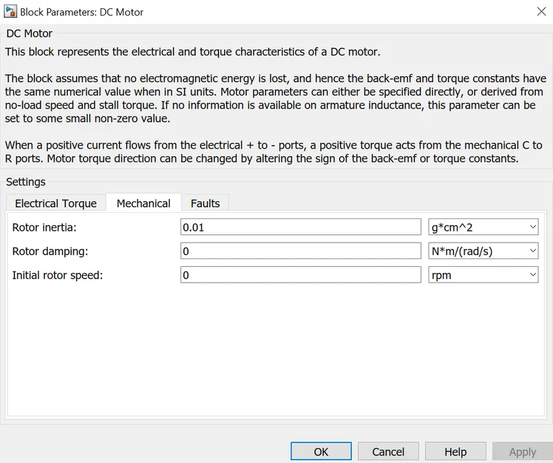
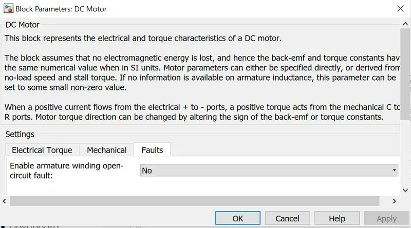
DC Motor block represents the electrical and torque characteristics of the motor. The positive and negetive terminals are connected to the Hbridge and the ground. C and R are the mechanical ports which are connected to the respective mechanical gear. There is a connection port across it to connect it further with the mechanical system. Connection port 4 is given to the shaft.
These are the parameter values for the given block:
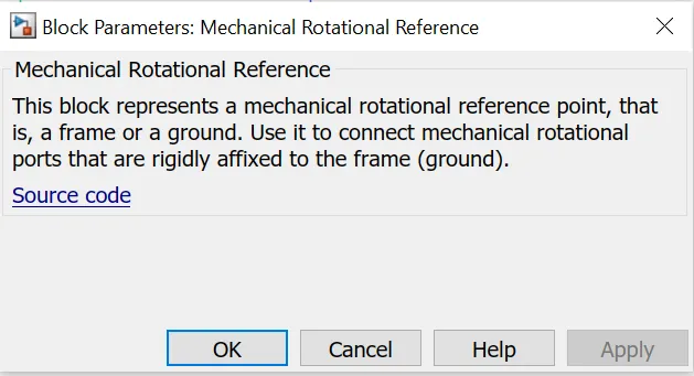
Mechanical rotational reference: Mechanical part of dc motor with C terminal is connected to mechanical rotational reference.
Solver configuration:
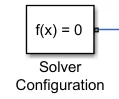
Here each physical network represented by a connected simscape block is connected to the solver configuration for the simulation to run properly. It specifies the solver parameters that the model needs before starting the simulation.
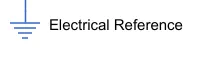
Electrical reference: Each electrical block is connected to an electrical reference or a negetive ports are grounded together.
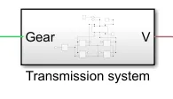
Transmission system subsystem:
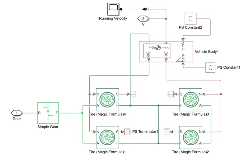
It is basically the vehicle body subsystem which consists of a simple gear, vehicle tire, vehicle body. Wheels are connected to the vehicle body of electric car.
Simple gear:
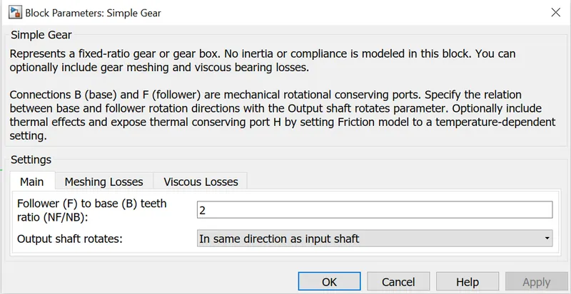
It represents a gear box that constraints the connected driveline axes of base gear and follower gear to corotate with a fixed ratio that we provide. We can choose the follower axis rotation which is either in same direction or in opposite direction. Here we are seleting rotation in same direction.
Tire :
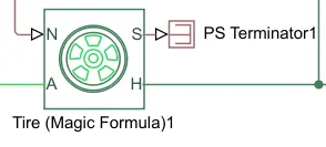
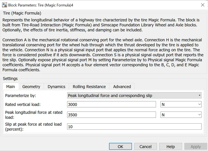
It models a tire with longitudinal behaviour. The block can model tire dynamics in constant and variable pavement conditions. It models the tire as a rigid wheel tire combination in contact with the road and subject to slip.
Vehicle body:
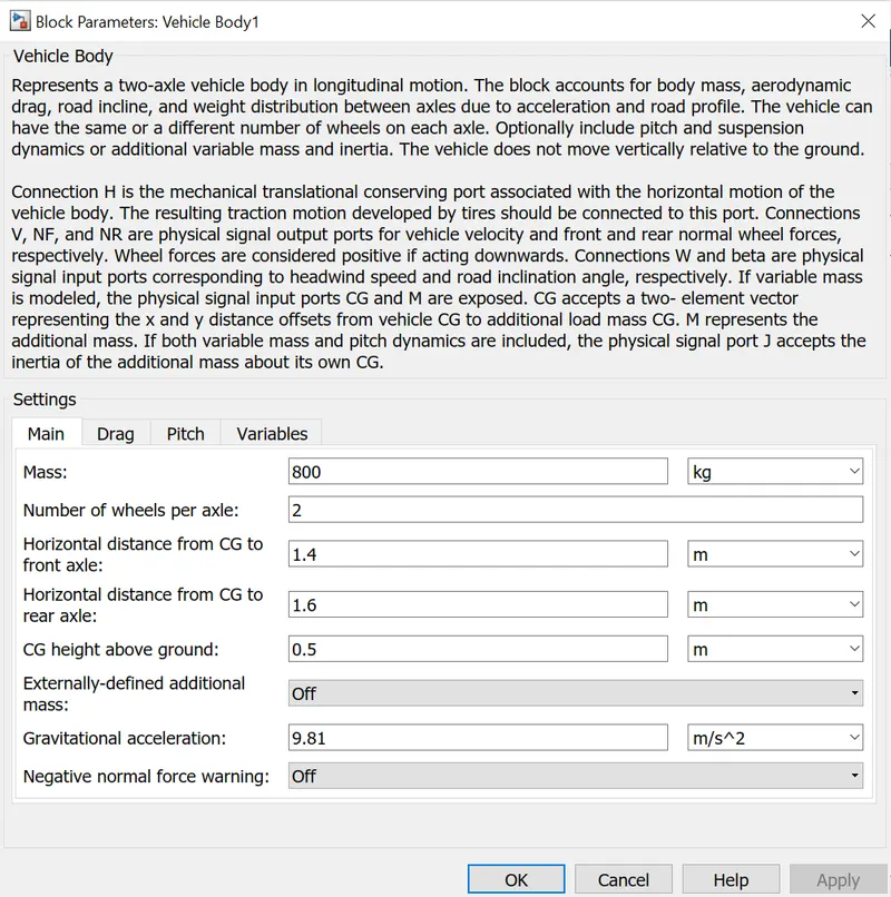
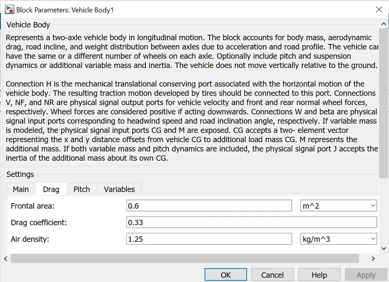
It represents 2 axle vehicle body in longitudinal motion. It can have same or different number of wheels or tires on each axle. Here there is 2 wheels on each axle. The block accounts for body mass, aerodynamic drag, road inclination, road profile etc.Vehicle body is used as a control mechanism.
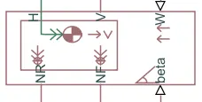
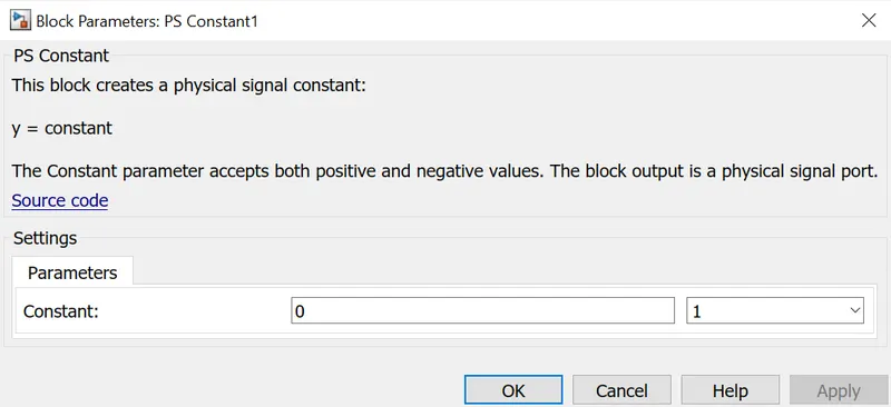
PS Constant bock: It generates physical signal of a constant value. Here there is 2 PS constant blocks used connected across W and Beta ports of veicle body.
Battery subsystem:
It consists of battery, controlled current source, rate transition block, gain block, discrete time integrator, add block, constant block, connection port.
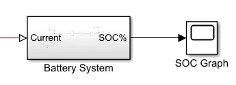
Here we need a battery model SOC or state of charge with respect to the voltage and charging and discharging current. With this battery model we can update the depth of discharge of battery to know its draining.
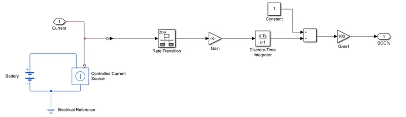
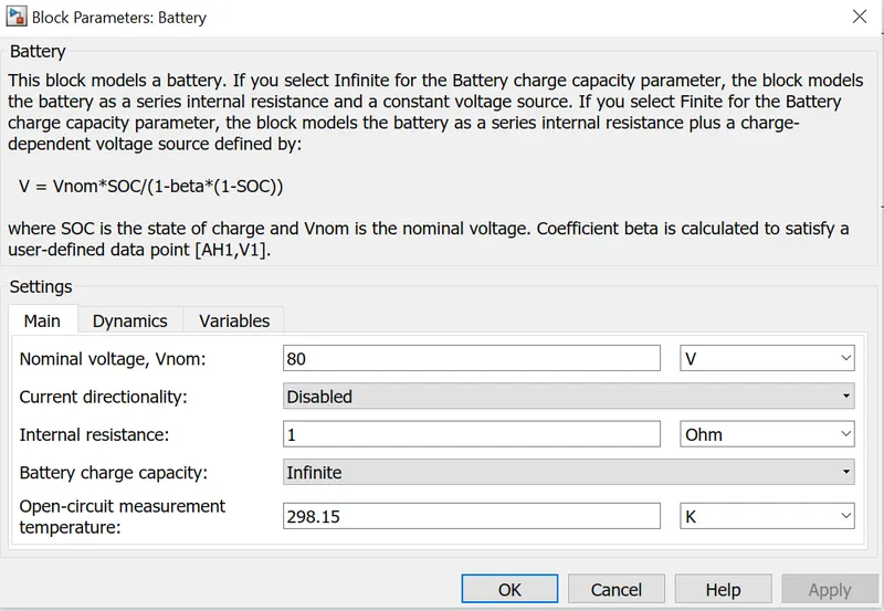
These are the parameter values for the given blocks:
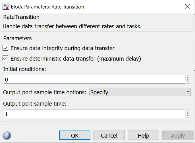
Rate transition block transfers the data from the output of a block operating at one rate to the input of a block operating at a different rate. In the above model it transfers data from the battery current to calculate the SOC of the battery.
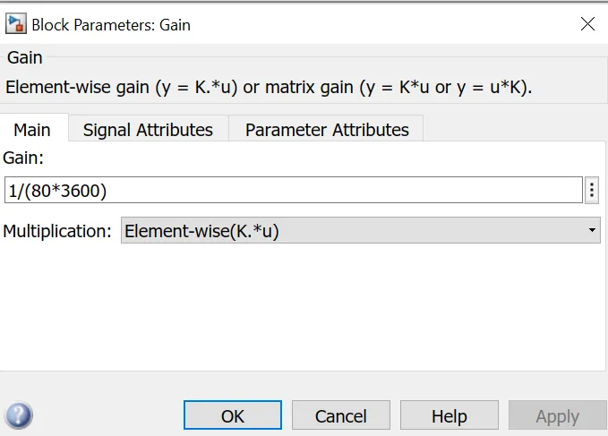
The Gain block multiplies the input by a constant value. Here the value is given as 1/ (nominal voltage*3600).
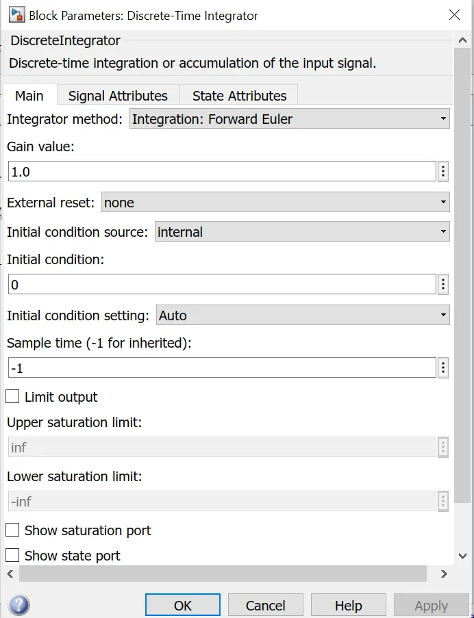
Discrete time integrator:
It is used in place of a integrator block to create a purely discrete model. We can define initial conditions, input gain value, upper and lower limits on the integral.
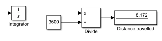
- Distance travelled is measured in the scope in which the vehicle speed is obtained from the transmission subsystem and it is given to the integrator block which is again divide with 3600 to measure the distance in km.
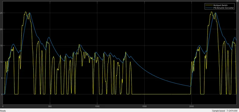
RESULT OBTAINED: Results for FTP drive cycle are provided. Here multiport is given to 1.
- Velocity graph: Vehicle speed and drive cycle velocity is shown together.
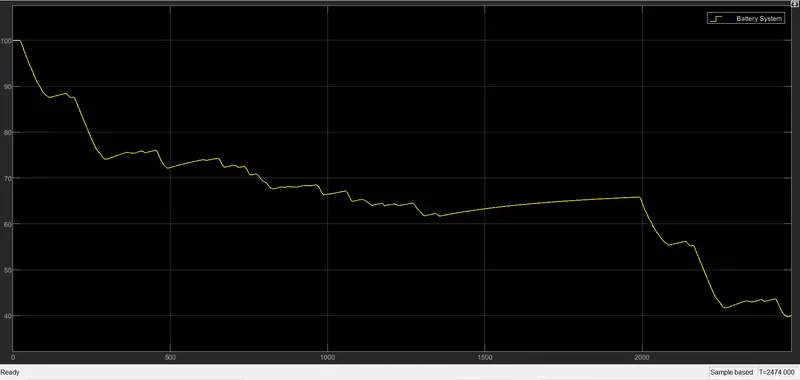
2. SOC discharge graph: Battery discharge is visible as SOC drops.
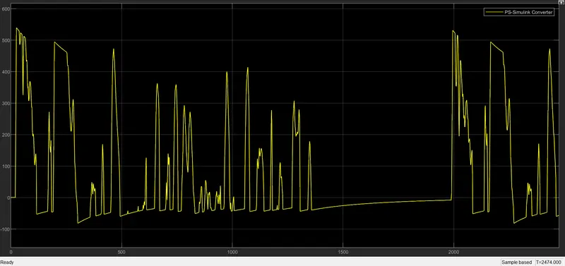
Current waveform from current sensor of motor controller:
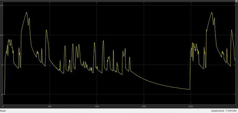
Voltage sensor output from motor controller :
Transmission system velocity output waveform:
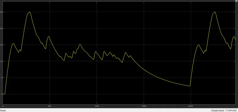
Distance travelled my car: 8.1 km
https://drive.google.com/file/d/1IXpk5o5GVAwN-sRwq_VN_wpxCTdWCahX/view?usp=sharing
Conclusion:
MATLAB model of an electric car is developed. Related plots are attached. All parameters values are given in description and detailed report is provided.