Final Project: Design of an Electric Vehicle
AIM: To create a MATLAB model of an electric car using battery and a DC motor by choosing suitable blocks from Powertrain blockset.
OBJECTIVES: To prepare a Technical report about the EV model including :
- System level configuration.
- Model Parameters.
- Results.
- Conclusion.
THEORY :
An electric vehicle (EV)is a vehicle that uses one or more electric motors for propulsion. It can be powered by a collector system with electricity from extravehicular sources, or it can be powered autonomously by a battery (sometimes charged by solar panels or by converting fuel to electricity using fuel cells or a generator). EVs include, but are not limited to, road and rail vehicles surface and undewater vessels,electric aircraft and electric spacecraft.
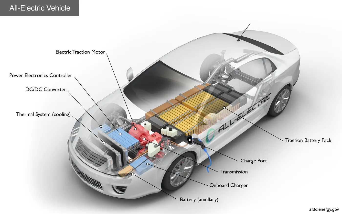
WORKING OF A BATTERY OPERATED ELECTRIC CAR:
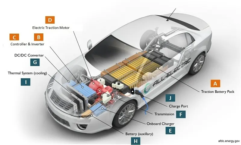
When the car pedal is pressed, then:
- Controller [C] takes and regulates electrical energy from batteries [A] and inverters [B]
- With the controller set, the inverter then sends a certain amount of electrical energy to the motor (according to the depth of pressure on the pedal)
- Electric motor [D] converts electrical energy into mechanical energy (rotation).
- Rotation of the motor rotor rotates the transmission so the wheels turn and then the car moves.
ELECTRIC VEHICLE COMPONENTS:
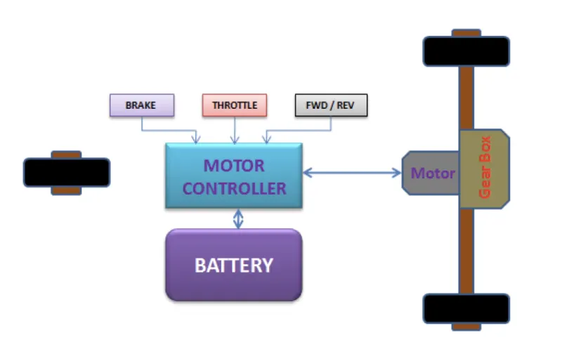
The basic main elements of electric cars installed in almost all types of electric cars are as follows:
- Traction battery pack:
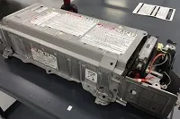
The function of the battery in an electric car is as an electrical energy storage system in the form of direct-current electricity (DC). If it gets a signal from the controller, the battery will flow DC electrical energy to the inverter to then be used to drive the motor. The type of battery used is a rechargeable battery that is arranged in such a way as to form what is called a traction battery pack.There are various types of electric car batteries. The most widely used is the type of lithium-ion batteries. - Power Inverter:(For EVs using AC motors)
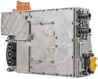
The inverter functions to change the direct current (DC) on the battery into an alternating current (AC) and then this alternating current is used by an electric motor. In addition, the inverter on an electric car also has a function to change the AC current when regenerative braking to DC current and then used to recharge the battery. The type of inverter used in some electric car models is the bi-directional inverter category. - Controller:
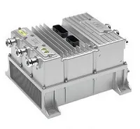
The main function of the controller is as a regulator of electrical energy from batteries and inverters that will be distributed to electric motors. While the controller itself gets the main input from the car pedal (which is set by the driver). This pedal setting will determine the frequency variation or voltage variation that will enter the motor, and at the same time determine the car’s speed.
In brief, this unit manages the flow of electrical energy delivered by the traction battery, controlling the speed of the electric traction motor and the torque it produces. This component will determine how electric car work. - Electric Traction motor:
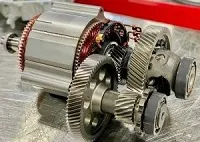
Because the controller provides electrical power from the traction battery, the electric traction motors will work turning the transmission and wheels. Some hybrid electric cars use a type of generator-motor that performs the functions of propulsion and regeneration. In general, the type of electric motor used is the BLDC (brushless DC) motor.
PROCEDURE:
- Vehicle body Subsystem:
- The vehicle is assumed to be Front axle driven (4 wheels-2 on each axle).
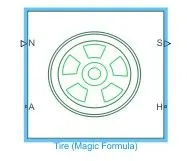
- The wheels are modelled using simple Tire(Magic formula) simulink blocks.
-
Connection N is a physical signal input port that applies the normal force acting on the tire.
-
Connection A is the mechanical rotational conserving port for the wheel axle.
-
Connection H is the mechanical translational conserving port for the wheel hub through which the thrust developed by the tire is applied to the vehicle
-
Connection S is a physical signal output port that reports the tire slip.
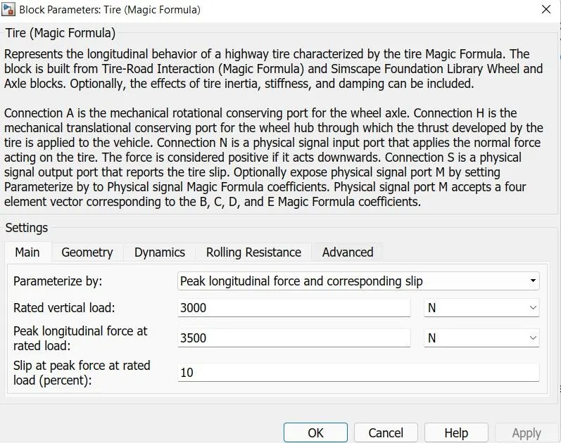
- The Tires are parameteized by peak longitudnal force and corresponding slip.
- The other block parameters such as -rated vertical load, Peak logitudinal force at rated load, Slip at peak force at rated load are kept at default values.
- The tire radius is given as 0.43m.
- The tire inertia is kept at 1Kg-m^2.Also, the rollling resistance coefficient is kept at 0.015.
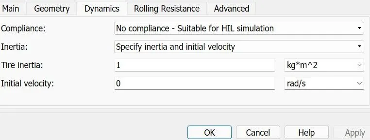
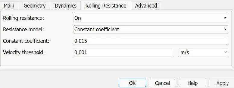
- The 2axle(4 wheel) assembly is now connected to the Vehicle Body simscape block.
-
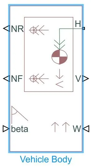
This block represents a two-axle vehicle body in longitudinal motion. The block accounts for-
Body mass
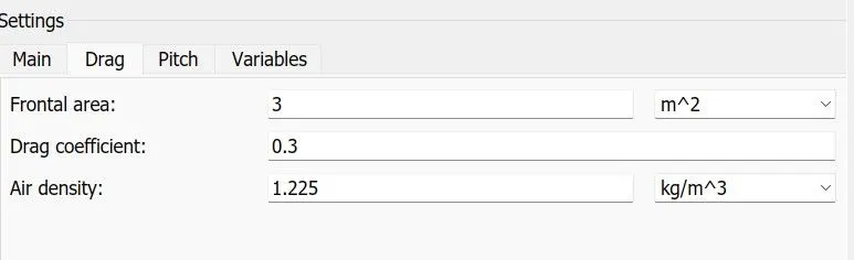
Aerodynamic Drag
road incline
weight distribution between axle
road profile. -
Connection H is the mechanical translational conserving port associated with the horizontal motion of the vehicle body. The resulting traction motion developed by tires should be connected to this port.
-
Connections V, NF, and NR are physical signal output ports for vehicle velocity and front and rear normal wheel forces, respectively.
-
Connections W and beta are physical signal input ports corresponding to headwind speed (wind opposing the vehicle direction) and road inclination angle, respectively.
- The gross weight is given to be 1200Kg.
- The Geometric parameters of the vehicle are given as:
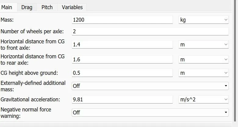
- To account for proper Drag Force, the drag parameters are kept as-
- The Pitch parameters are not considered for this simulation.
- The complete subsytem is as shown below:
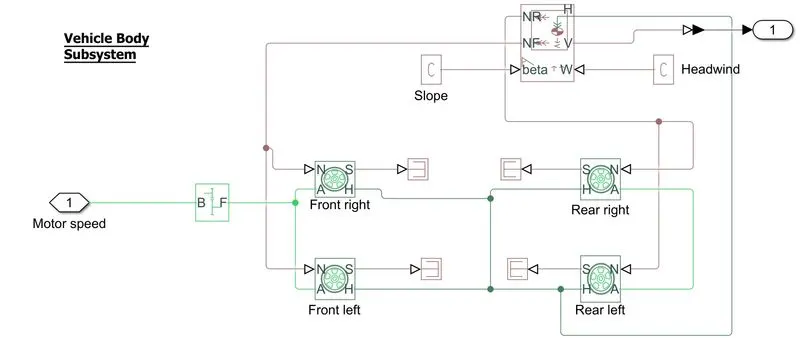
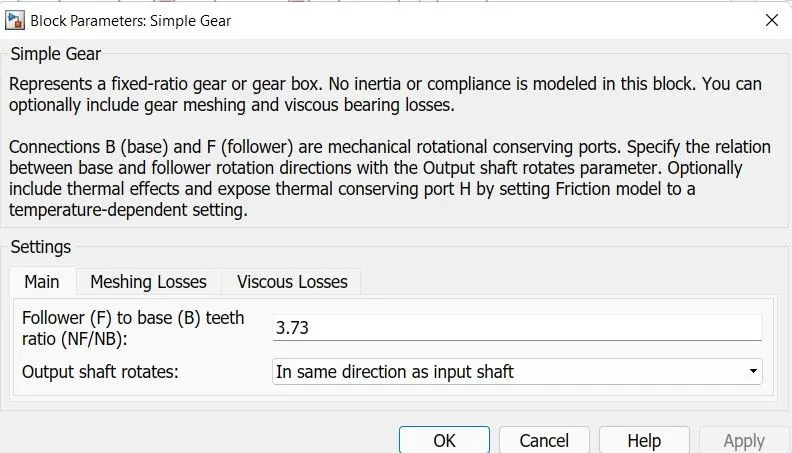
- The input for this Subsystem is taken as the rotational speed of the motor. The input is fed to the Front axle through a Simple gear representing the Final Drive Ratio of 3.73
Here, the rotational direction of the output shaft is kept the same as the input shaft. Also, no meshing losses are considered for simulation.
(2) DC Motor :
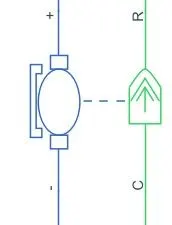
- Simulink provides an inbuilt block model for DC Motor which converts electrical input into mechanical rotational output.
Note: Here, the blue colour represents the electrical side of the motor and the green side represents the mechanical side of the motor. - Here, the model field type is kept as Permanent magnet and the model parameterization is done by rated load and speed.
The armature inductance and mechanical parameters are kept at their default values.
All the other parameters are changed as shown below:-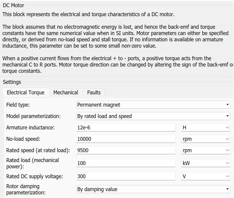
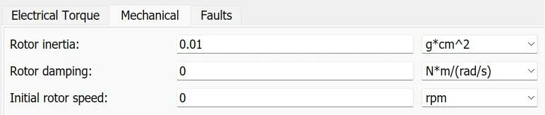
- The connection R represents the Rotor (rotational output) while the connection C is for the casing (stationary). Thus the R port is connected to the input of the vehicle subsystem created earlier. The C port is connected to a mechanical rotational reference.
- The '+' and '-' terminals of the motor are connected to the motor controller. If these terminals are directly connected to the battery, the required DC motor will run on the rated capacity of the battery. This will eventually result in no control over the DC motor and the vehicle will run at the top speed throughout the simulation. Thus,a motor controller is very much needed.
(3) Motor Controller :
- H-bridge circuit-

- This block represents an H-bridge motor drive. This block can be driven by the Controlled PWM Voltage block in PWM or Averaged mode.
- In PWM mode, the motor is powered if the PWM port voltage is more than the threshold voltage enabled.
- In Averaged mode, the PWM voltage divided by the PWM signal amplitude gives amplitude parameter defines the ratio of the on-time to the PWM period.
- Connection REF is for the reference input. This combined with the PWM connected will form the pulse input for H-Bridge.
Here, the REF input is connected to the Electrical Reference(ground). - Connection REV refers to the reverse motion of the vehicle (motor) which essentially means, the backward motion of the vehicle.
Here, the reverse motion has not been taken into account and so, the port is connected to electrical reference. - Connection BRK is for the BRAKING of the vehicle.
- Since, the PWM mode results in a huge amount of simulation time, Averaged mode is selected for this simulation.
- Load current charcteristics are taken to be smoothed here.
- Also, the regenerative braking is enabled for this simulation. This means, when the vehicle starts decelerating, the correesponding amount of charge will be fedback to the battery.
Accordingly, the BRK input is connected to a Controlled Voltage source. This will generate emf corresponding to the intensity of the brakes applied and feed the power back to the battery.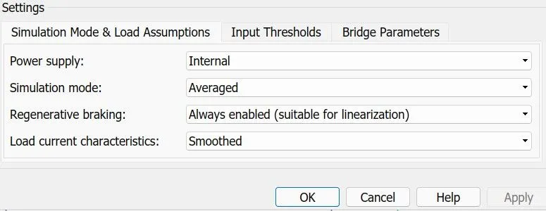
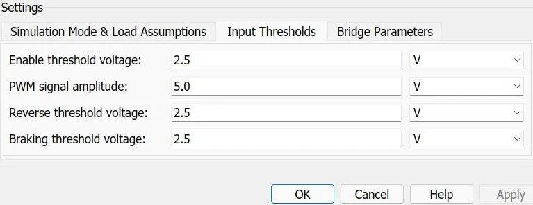
- The input Thresholds parameters are kept at their default values.
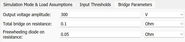
- The output voltage magnitude of the H-bridge is given the same value as the rated DC supply voltage of the motor.
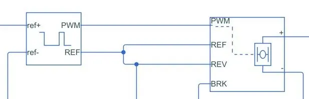
- Simulink provides an inbuilt Controlled PWM Voltage block. This block is used for providing the proper pulse inputs to the H-bridge circuit.
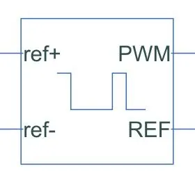
The PWM and REF ports are for the corresponding H-bridge circuit inputs.
The two reference inputs correspond to the throttle inputs given by the driver. The block generates corresponding pulse width as per the accelerations and brakes applied by the driver himself. - Here, the PWM frequency is 1000Hz. Also, the simulation mode is PWM mode.
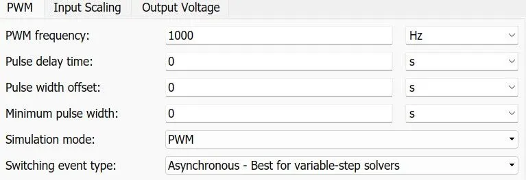
- The input scaling parameters are given are-
0 for 0% duty cycle and 5V for 100% duty cycle. Accordingly, the output voltage amplitude becomes 5V. - The H-bridge circuit along with the PWM input, together form the motor controller circuit..
(4) Longitudnal Driver:
- Longitudnal Driver is an inbuilt block provided in the powertrain blockset.
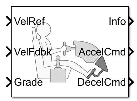
- It is parametric longitudnal speed tracking controller for generating normalized Acceleration and Braking commands based on reference and feedback velocities.
- The VelRef is the reference velocity port where the input drive cycle data is fed.
The VelFbdk port is the feedback velocity. The actual velocity ouptut given by the vehicle body is given here. By comparing the actual(feedback) velocity with the reference velocity, the driver block generates acceleration and braking signals in order to minimise the error between the two concerned velocities.
Grade corresponds to the grade angle. For this simulation, no inclination is considered and hence, a constant block with value 0 has been connected.
Info gives the ouput for the bus signals for different block calculations like difference in reference vehicle speed and vehicle speed etc.
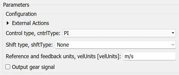
AccelCmd and DecelCmd correspond to the acceleration commands and deceleration commands generated respectively and are connected to the correponding ports of the Controlled PWM Voltage block. - Here, the selected control type is PI . Accordingly, the block implements the proportional-integral (PI) control with tracking windup and feed-forward gains.
(5) Battery Pack:
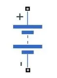
- To model the battery pack, a simple battery block is used. This is because, if the generic battery block is used instead, the simulation will run for a longer time.
- Here, the selected option for the Battery Charge Capacity is Finite. Accordingly, the block models the battery as a series internal resistance plus a charge dependent voltage source.
If the chosen option had been infinite, the voltage source would have been constant. - Also, the self-discharging of the battery and battery dynamics are disabled.
- The Battery Nominal Voltage is given as 400V.
The Ampere-hour rating is assumed to be 50.
The rest all parameters are kept at their default values.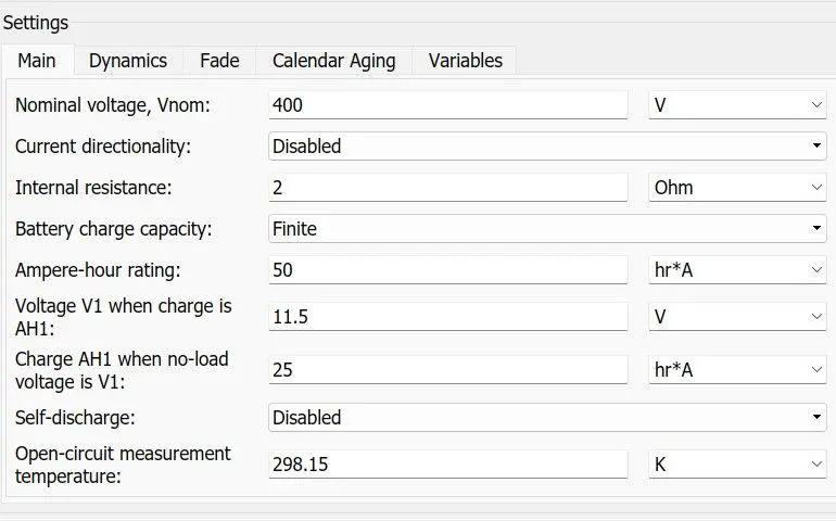
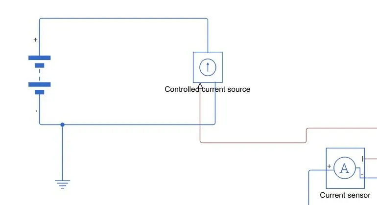
- To ensure, the Battery supplies current as per the requirements of the motor controller and not the rated current, a Current Sensor & Controlled Current Source pair is connected.
(6) Reference Velocity(Drive Cycle):
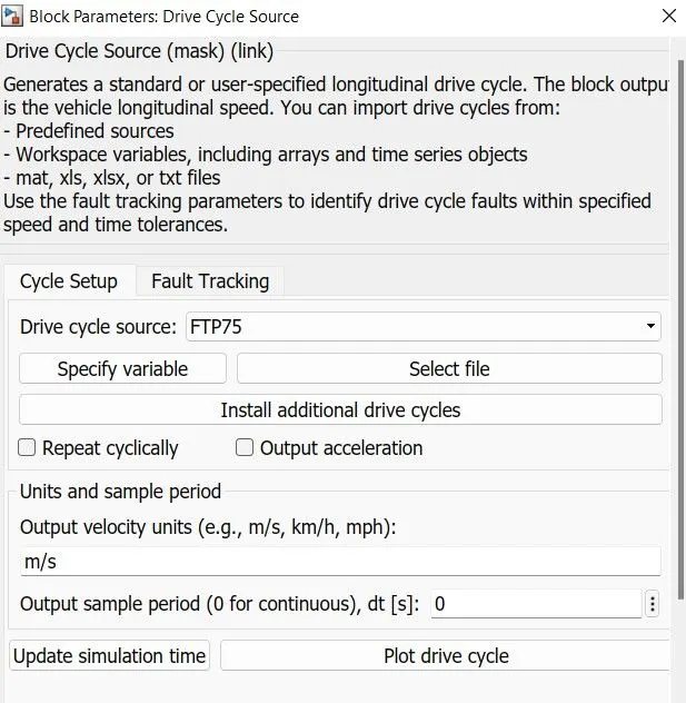
- The Drive Cycle Source block is used to provide the reference velocity for the simulation.
- It generates a standard or user-defined longitudnal Drive Cycle.
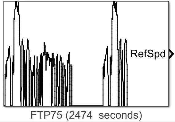
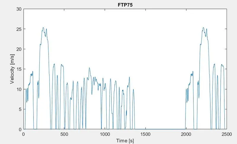
- Here, the standard Drive Cycle is FTP75.
- The Plot of the Drive Cycle is shown below:
(7) Battery State of Charge:
- A small subsystem is created to calculate the State of Charge of the Battery.
- This subsystem takes the battery current as the input.
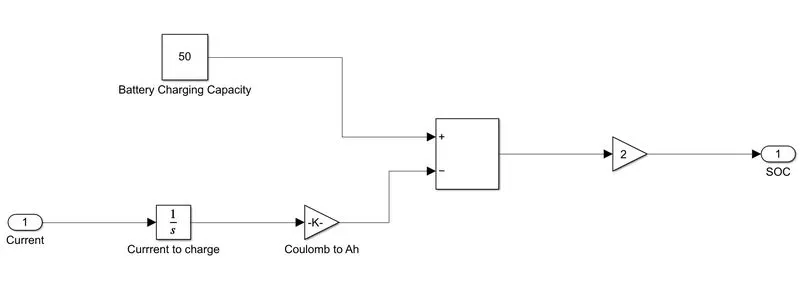
- The essential process to calculate the SOC is by subtracting the charge from the rated capacity of the Battery.
- Accordingly, the curent is integrated w.r.t time to get the charge in coulombs. Now, this coulomb value is modified into Ampere-hours.
This value is now subtracted from the charging capacity of the Battery i.e 50Ah. - Finally, the remaining charge is now converted into percentage value of the charging capacity of the Battery.
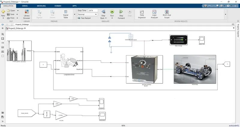
Model:
OUTPUT PLOTS AND OBSERVATIONS :-
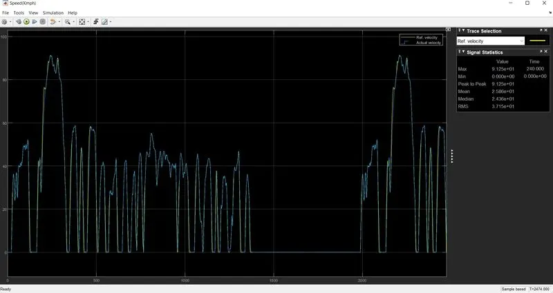
- Velocity Plot :
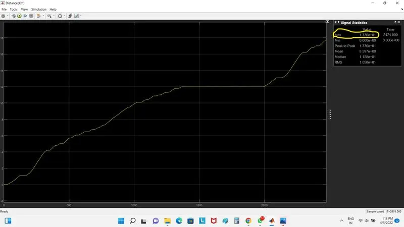
- Distance (Km) :
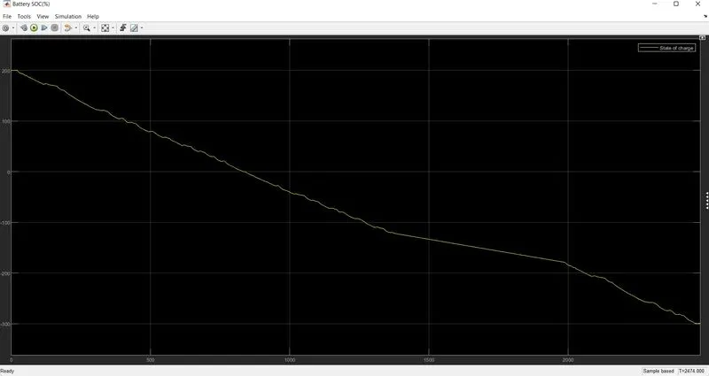
- Battery SOC :
OBSERVATIONS :-
- The Actual velocity plot and the reference plot almost overlap each other except at the instants when the vehicle accelerate or decelerate. The maximum speed achieved by the vehicle is 91.52 Kmph at around 241 sec.
- The total distance covered by the vehicle in the entire journey is around 17.7 Km. The distance graph has an increasing slope when the vehicle accelerates and a decreasing one when it decelerates.
- The Battery SOC graph decreases thoughout the journey and whenever the brakes are applied the graph shifts upwards as the battery gets charged at those instants due to regenerative braking.