Final Project: Design of an Electric Vehicle
1.
- An electric motor that converts electrical energy from the battery and transmits it to the drive train. Both direct-current (DC) and alternating current (AC) motors are used in these traction or propulsion systems for electric cars, but AC motors do not use brushes and require less maintenance.
- A controller that regulates energy flow from the battery to the motor allows for adjustable speed. Resistors that are used for this purpose in other electric devices are not practical for cars because they absorb too much of the energy themselves. Instead, silicon-controlled rectifiers (SCRs) are used. They allow full power to go from the battery to the motor but in pulses so the battery is not overworked and the motor is not underpowered.
- Any kind of brakes can be used on electric automobiles, but regenerative braking systems are also preferred in electric cars because they recapture some of the energy lost during braking and channel it back to the battery system.
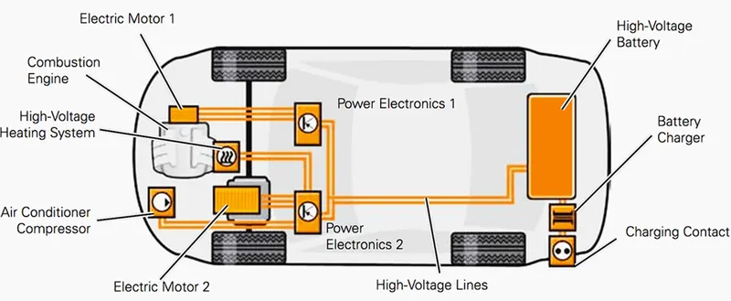
When the electric motor/generator is driven mechanically, it supplies electrical energy as an alternator. In principle, any electric motor can also be used as an alternator.Electric motors/generators used for propulsion are water-cooled. Air cooling would also be possible but complex due to space and the amount of heat generated.In full hybrid vehicles (HEV), the electric motor/generator also functions as the starter for the combustion engine.
Several pairs of permanent magnets are located on the rotor in this synchronous motor. Since the three coils are supplied sequentially with a current, together they generate a rotating electrical field that causes the rotor to rotate when the electric motor/generator is used to drive the vehicle.When used as an alternator, the movement of the rotor induces a three-phase alternating voltage in the coils that is transformed into a direct voltage for the high-voltage battery in the power electronics.The advantage of synchronous motors compared with asynchronous motors is the more precise control of the motor in automobile applications.The electric motor/generator is very environmentally compatible thanks to the lack of noise and harmful emissions. The electric motor/generator responds quickly, has and a high level of efficiency. In contrast to combustion engines, electric motors supply their nominal power steplessly over a broad rpm range.The maximum torque is available even at low rpm (i.e. when pulling away) and only drops once the motor reaches very high speeds. As a result, neither a manually operated transmission, an automatic transmission nor a clutch are required.
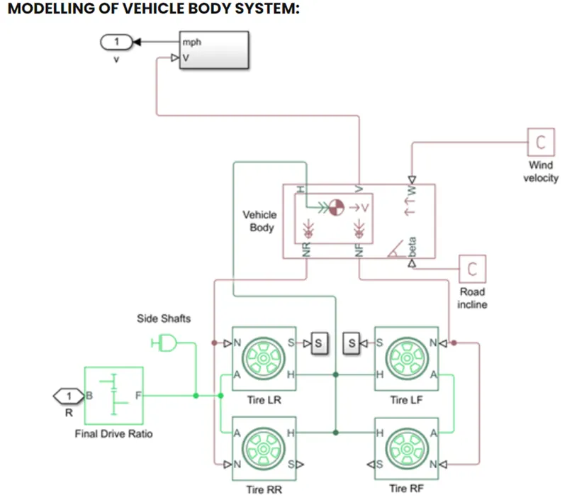
The vehicle block represent the longitudinal motion,Wheel axle
NF:Normal force acting in front tyre
NR:Normal force acting in rear tyre
Beta:-Road Inclination
V:Velocity of vehicle
W:wind speed
Mass of Vehicle taken as 1300 kg
Number of wheel per axle:2
CG from front axle: 1.5m
CG from ground height:0.4m
G=9.81m/s^2
Frontal Area=2.5m^2
Drag coeff= 0.20
Air density=1.2kg/m^3
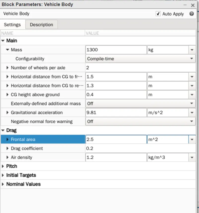
Tyre Modelling:-
N: normal force acting in tyre
S:Slip of tyre
H:hub
A:axle
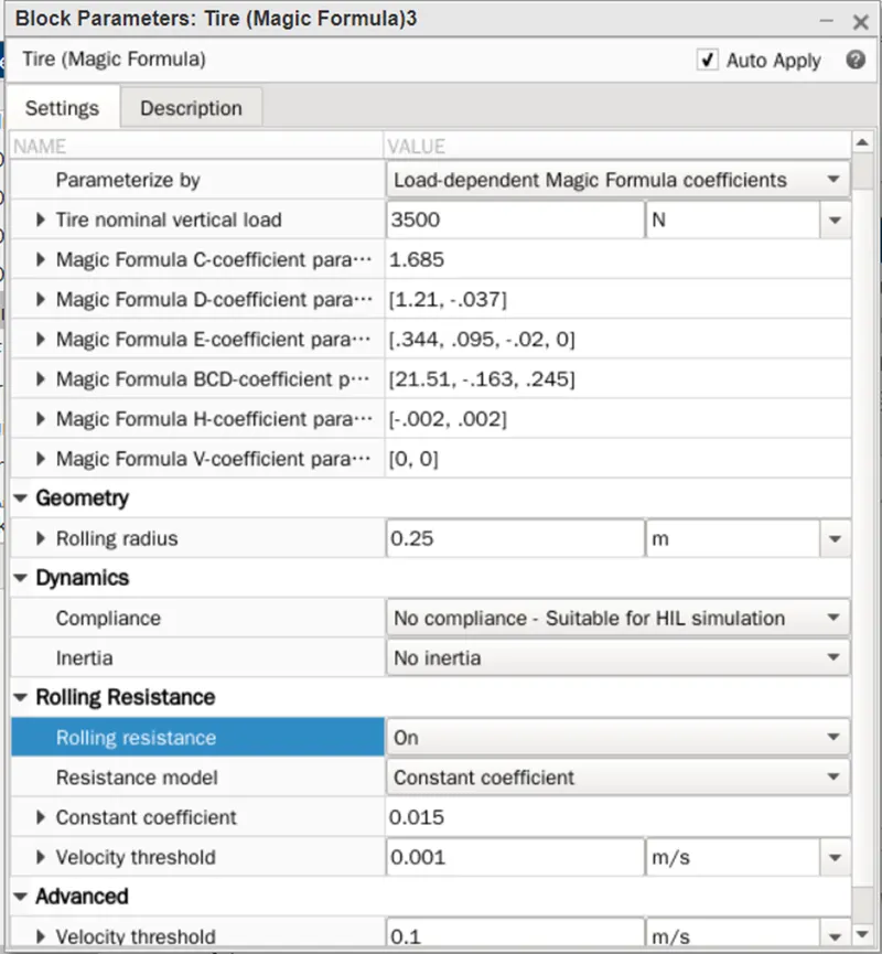
The following values were taken for tyre
Parameterisze :load dependent magic formula coeff
Norminal load:3500N
Magic coeff is taken as it is C,D,E,BCD,H,V
Rolling radius:0.25
Rolling resistance:0.015
Velocity threshold 0.001m/s
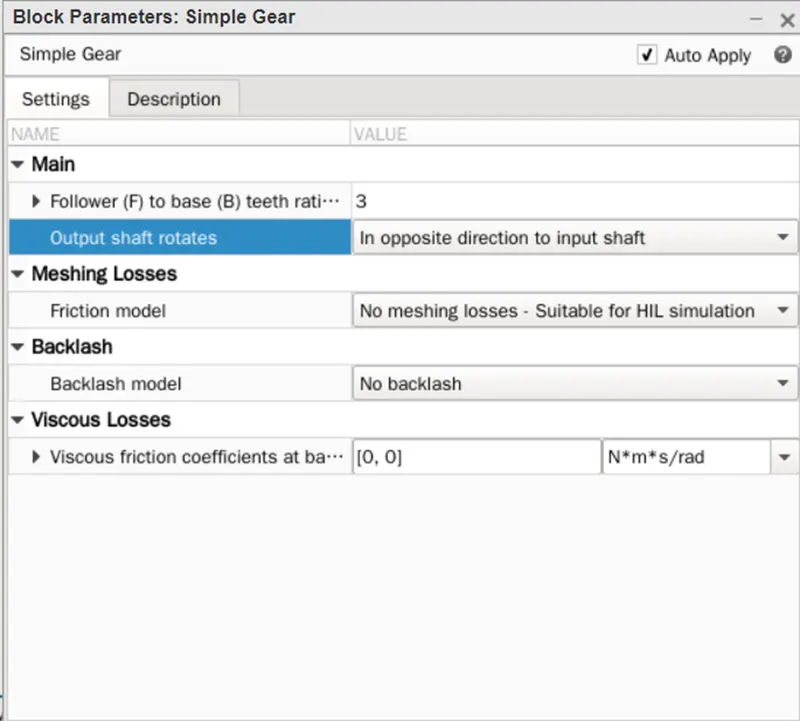
SimpleGear:-
B:output of base gear is connected with input of DC motor
F;Follower gear is connected with axle (here Rear)
Gear ratio can be vaired in Simple gear block
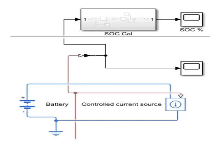
State of charge:-
State of charge is defined as the ratio of current charge to rated battery capacity
+ is connected to current source
‘-‘ is connected to ground
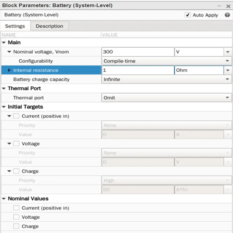
Battery:-
Vlotage taken as 300
Internal resistance 1 ohm
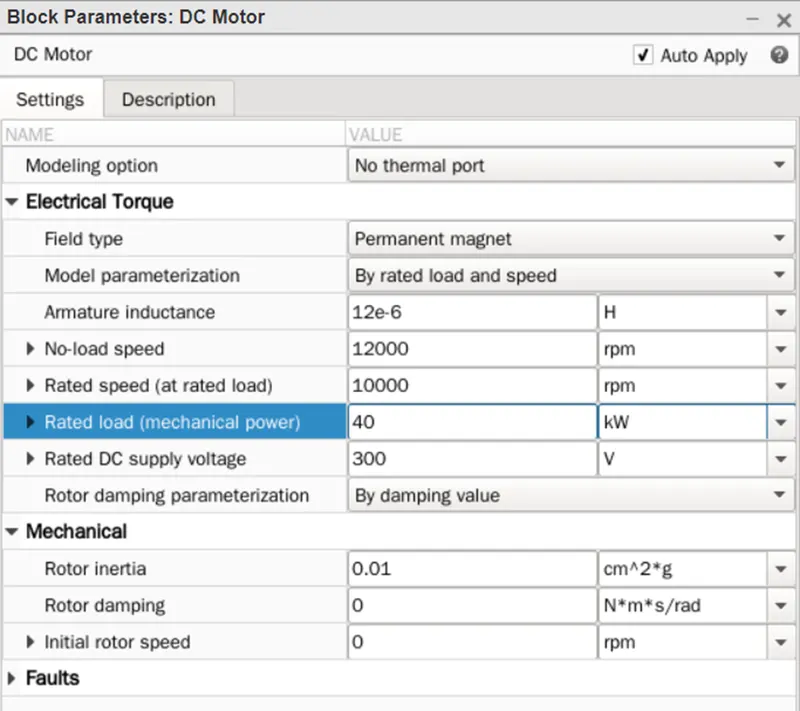
DC motor is taken as field Permanent Magnet
No load Speed:12000 rpm
Rated Speed:-10000 rpm
Rated load:40 kW
Rated Supply:300
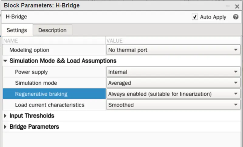
H bridge:-
Power supply is taken Internal
Simulation mode is Average
Regeneration braking: Always enabled
Load current characterstics:-Smoothend (for linearisation)
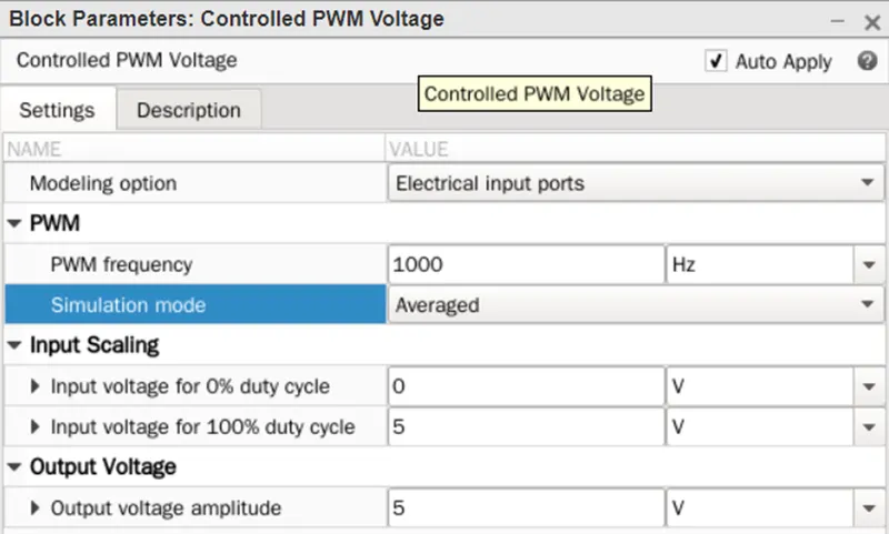
Controlled PWM Voltage:-
Ref+ :-Positive termindal connected with voltage positive terminal
Ref-:- negative terminal connected with controlled voltage negative terminal side
PWM:Pulse width modulated signal,
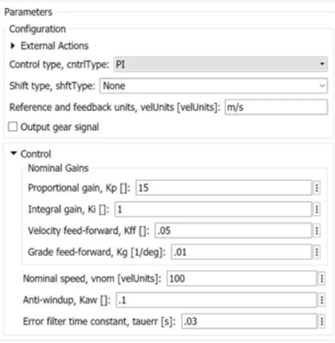
Longitudinal driver:-
Control Type:Propotinal integral type
Vel ref: ref vehicle is connected with speed result block
Grade:road grade
Accelcmd-acceleration is connected with controlled voltage source input signal
Velfdbk-Vehicle feedback
Drive cycle source is taken WOT
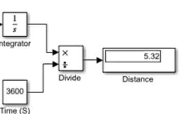
Integrator Block is connected to vehicle body
Divide block is connected to get the distance
Time block is taken for one min cycle