Final Project: Design of an Electric Vehicle
Aim:
Create a MATLAB model of electric car which uses a battery and a DC motor. Choose suitable blocks from Powertrain block set. Prepare a report about your model including following:
Objectives:
1. System level configurations
2. Model parameters
3. Results
4. Conclusion
Background Theory:
An Electric vehicle ia a vehicle that uses aone or more electric motors or traction motors for propulsion. An electric vehicle may be powered through a collector system by electricity from off vehicle sources, or may be self cotained with a battery, solar panels, fuel cells or an electri generator to convert fuel to electricity.
MATLAB model of electric car which uses lithium-ion battery and induction motor.
To model & Simulink an electric vehicle with Simulink. In Modelling this EV for a drive cycle and to check performance parameter: to measure speed, SOC, and the current characteristics of it's battery system etc
Block Diagram of EV:
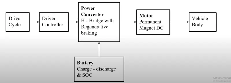
The main components of the modelling EV in Simulink are,
- Drive Cycle
- Motor & Controller
- Power Converter
- Batteries
- Vehicle Body
1) Battery: An electric vehicle battery (EVB, also known as a traction battery) is a battery used to power the electric motors of a battery electric vehicle (BEV) or hybrid electric vehicle (HEV). These batteries are usually rechargeable (secondary) batteries, and are typically lithium-ion batteries. These batteries are specifically designed for a high ampere-hour (or kilowatt-hour) capacity.
i) Lithium-Ion Batteries- This battery technology gives extra performance and range. However, it also carries the highest price tag. Lithium-ion batteries are lighter than Lead acid and Nickel Metal. These are also the batteries usedin digital cameras & smartphones.
ii) Lead Acid Batteries- This battery technolody is the most popular. It is also the cheapest among the battery technologies. It is nearly 97% recyclable.
iii) Nickel Metal Hydried Batteries- This Battery technology provides higher output and better performance but it costs much more than lead-acid batteries.
2) Motor Controller: The motor controller of an electric car administers its complete operation & the distribution of its power at any given moment. It helps monitor and regulates all key performance indications such as variable operator, motor, battery and acceleration padel. It has a microprocessor which can limits or redirect current. It is used to either improve the mechanical performance of the car or suit the operator's driving style. There are also more refined controllers which are capable of greater accuracy and thus, higher efficiency.
3) Electric Motor: Unlike gasoline engine which has lots of moving parts, a electric motor has only one moving part and that is shaft. This makes it a very reliable source of motive power. Choosing an electric motor depends on the car's system voltage. They can be structured to use either AD or DC current. AC motors are less expensive and lighter compared to DC motors. They are also more common and they tend to suffer from less mechanical wear and tear.
Simulink Model:
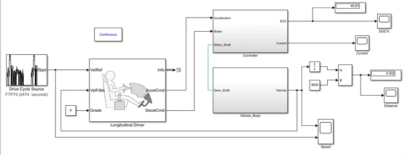
Vehicle Body Subsystem:
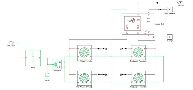
Vehicle Body Subsystem consists of following blocks.
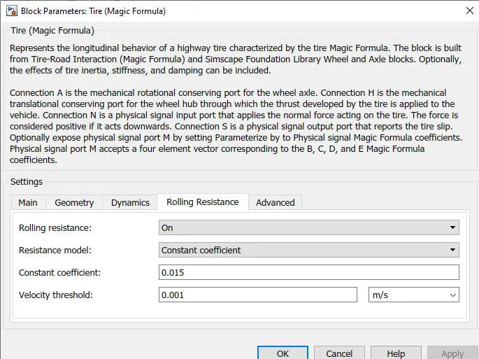
1. Tires: The vehicle assume to be front axle driven for that we use Tire(Magic Formula) simulink block.
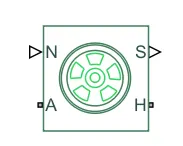
Input (N)- Normal reaction force acting on tire.
Output (S)- Slip value relative to tire & surface of contact.
Conserving Port (H & A)- where A represents axle on which tire are mounted and H represents wheel Hub which transmits thrust generated by the wheel to the body of the wheel.
2. Gear:
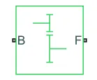
The Simple gear block represents a gearbox that constrains the connected driveline axes of the base gear (B) and the Follower gear (F) to coratate with a fixed ratio that we specify.
3. Differential:
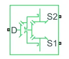
Using this block, we can add inertia and losses of gear machine and viscous gear friction. This block represenets a gear mechanism that allows the driven shaft to spin at different speeds.
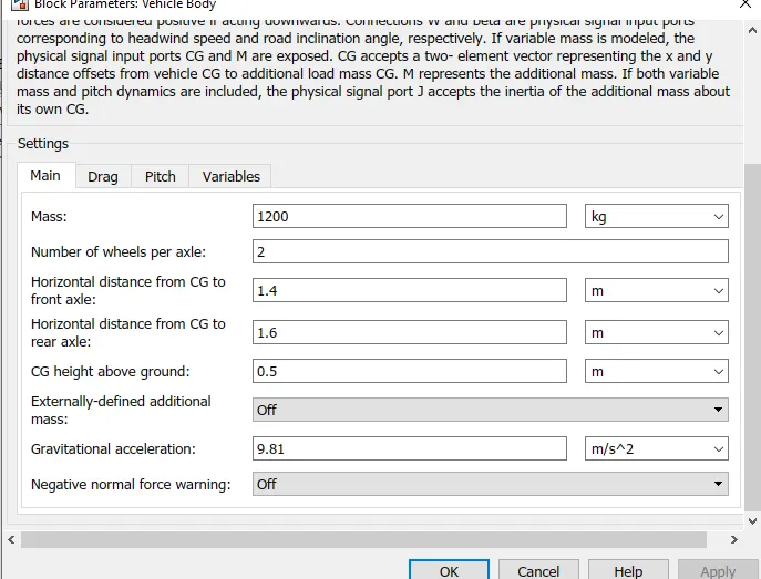
4. Vehicle Body: This block represents two axle vehicle body in longitudinal motion.
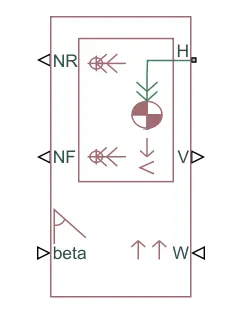
This block have Normal force on rear wheel (NR), Normal force on front wheel (NF), Angle of road inclination (BETA), mechanical translational conserving port hub (H), output translational velocity (V), Headwind speed of vehicle (W).
Controller Subsystem:
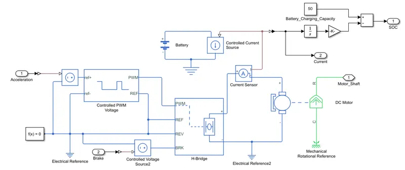
Controller Subsystem have following blocks,
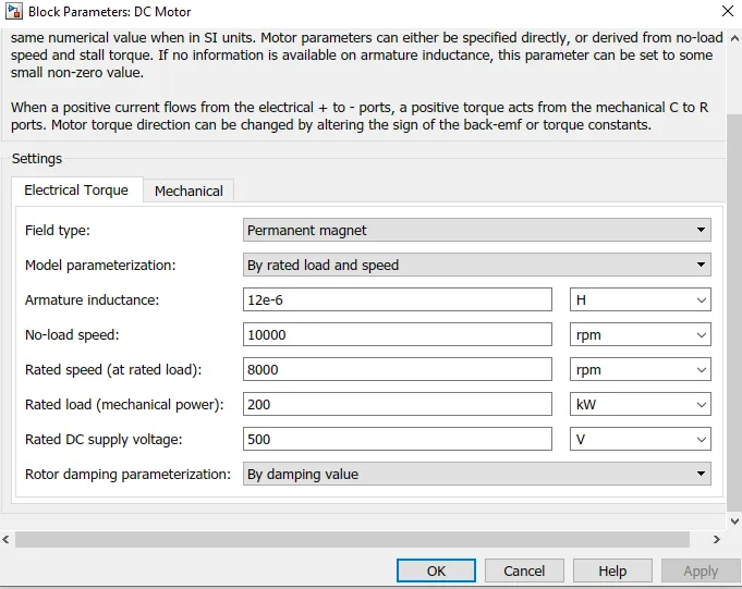
1. DC Motor: Simulink library proides an inbuilt DC motor block which converts Electrical input into mechanical rotational output.
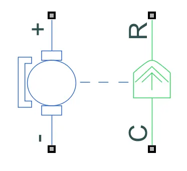
+ & - represents positive & negative terminal which are connected to the motor controller. R represents Rotor or rotational output (Shaft) while C is Casing (stationary) connect to mechanical rotational reference.
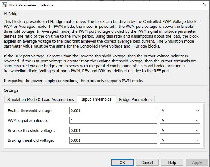
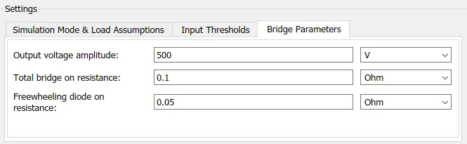
2. H-Bridge: The H-Bridge helps in controlling the power that is input according to the requirement. The outut provided are converted voltage as per the controlled parameters.
3. Battery:
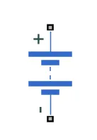
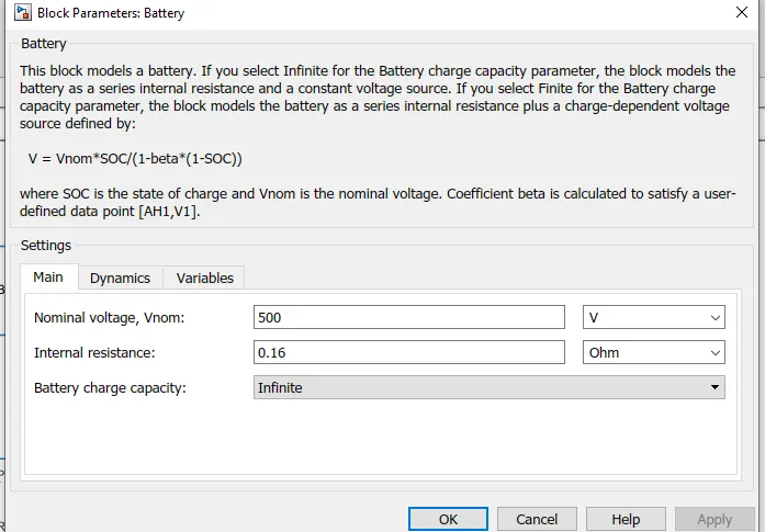
The battery is connected as the power soure to the model so that the power could be generated and the same is transmitted accordingly to all the operating sources.
4. Controlled PWM Voltage: The controlled PWM voltage block helps in keeping the modulated pulses as per the required pulses. So that the operation hapens smooth and higher variations are not observed.
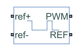
The PWM & REF connections are for the corresponding ports on the H-Bridge circuit. The 2 reference inputs corresponds to the throttle input given by the driver. The block generates corresponding pulse width as per the accelerations and brakes applied by the driver himself.
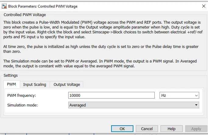
5. Battery State of Charge: A small subsystem is created to calculate the state of charge of the battery. The essential process to calculate the SOC is by substracting the charge from the rated capacity of the battery.
Accordingly the current is integrated w.r.t. time to get the charge in coulumbs. This value is now modified into Amp-hr.
Longitudinal Driver: Longitudinal Driver is an inbuilt block provided by the powertrain blockset.
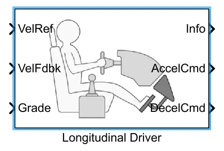
The Driver model has the input and output ports which are connected to the following.
Velocity reference - Driver Cycle
Velocity Feedback - Corresponds to the feedback velocity.
Grade - corresponds to the grade angle = 0
AccelCmd & DecelCmd corresponds to the acceleration and deceleration commands generated respectively and are connected to the corresponding ports of the Controlled PWM Voltage block.
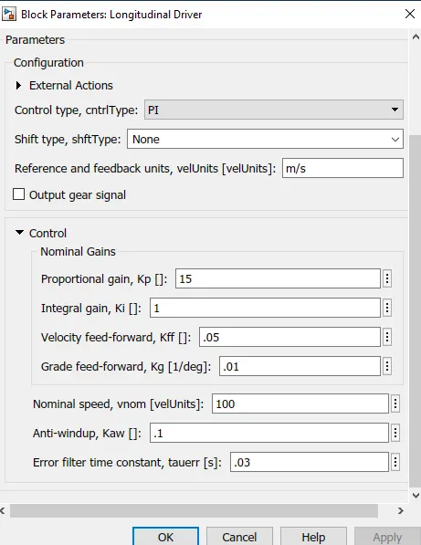
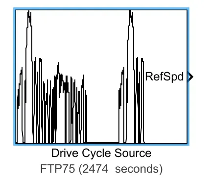
Drive Cycle: The Drive Cycle source blockis used to provide the reference speed for the simulation. It generates a standard or user specified longitudinal drive cycle.

Simulation:
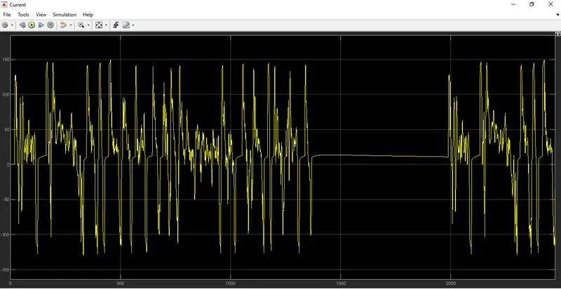
The system is run for 2474 sec which is the total time for which the input drive cycle is defined. A solver Configuration is added to ensure proper solving solving of the mathematical equations by the model.
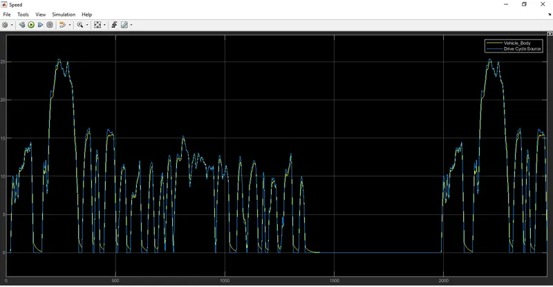
Scopes are connected to analyze different output such as the SOC of the battery, the reference velocity & the actual velocity of the vehicle and the distance covered by the vehicle during total run.
The 2 velocities are first convert from m/sec to km/hr for that we useGain block.
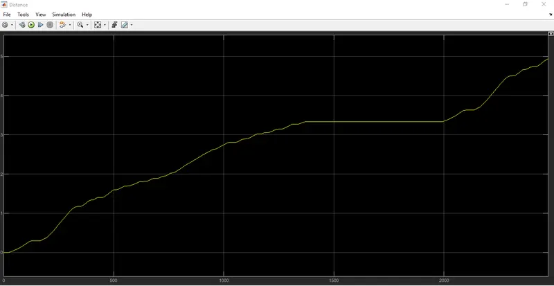
The distance is caalculated by simply time integration of the velocity.
Output:
1. Scope output from both velocity where Blue one represents Std or reference Drive cycle and yellow is from output of vehicle.
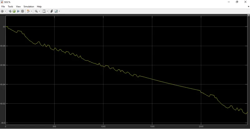
2. This scope showing the battery discharging or SOC plot during Drive cycle activation period.
3. Distance covered by Vehicle is in below graph.
4. Battery current:
Conclusion:
The model was succesfully run for simulation under the standard FTP75 drive cycle. The Result have been properly analysed.