Final Project: Design of an Electric Vehicle
AIM: Create a MATLAB model of electric car which uses a battery and a DC motor.
OBJECTIVES:
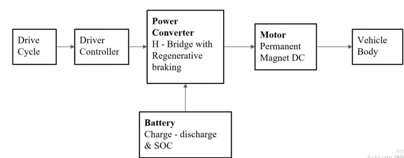
1. System level configurations
2. Model parameters
3. Results
4. Conclusion
THEORY:
Electric vehicles are different from the ordinary internal combustion engine operated vehicles. They use an elctric motor which can be a DC or an AC motor as a source of propulsion and as a source of fuel, EV's are dependent on the batteries. Electric vehicles are far more efficient than typical ICE vehicle and also gives us an ecofriendly option. So, the project includes modeling of an electric vehicle with the help of a battery and a DC motor.
1. SYSTEM LEVEL CONFIGURATION AND MODEL PARAMETERS:
BLOCK DIAGRAM
1) VEHICLE BODY:
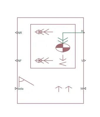
This is the vehicle body block which consist of hub, speed , normal force rear and normal force front as output ports as well as i can give road inclinationation angle (beta) and headwind(w).
I am assuming road inclination angle to be zero which means, it is a flat road and headwind on a normal day is 4km/h which is 1.11m/s.
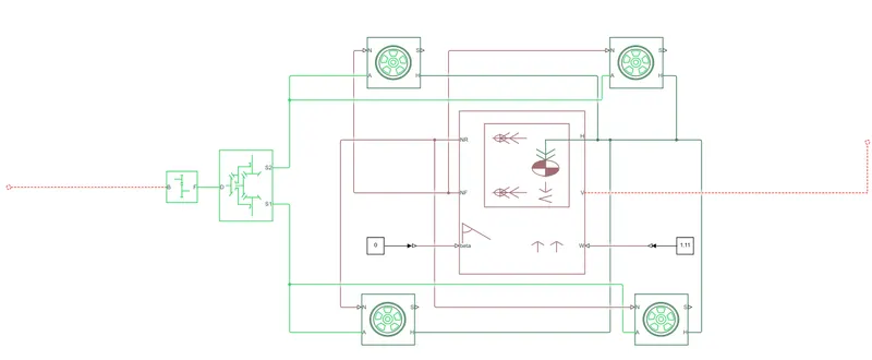
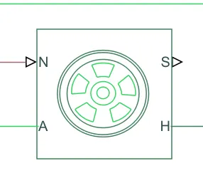
following is the vehicle body block connected with the four tires as well as differential and simple gear:
The range of wiegh for electrical vehicle varies from 1200 kg to 3000 kg. So, keeping that in mind, I am assuming weight to be 1800kg including the payload.
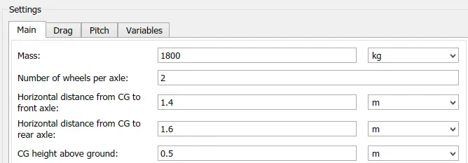
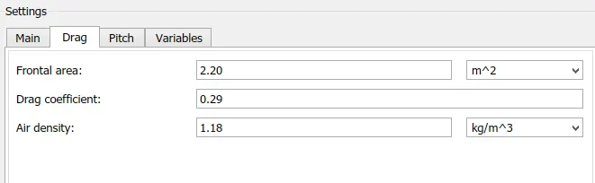
For an upper medium car, the frontal area limits to 2.20 m^2 with drag coefficient of 0.29.
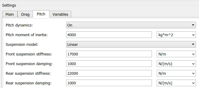
I am also considering the suspensions of the vehicle body and following are the values I have taken from a study, which are inserted in the vehicle body parameters:
TIRE CONSIDERATION FOR AN UPPER MEDIUM CAR:
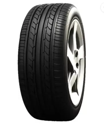
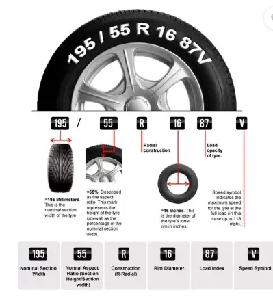
CALCULATING THE TIRE RADIUS:
Rim dia= 16inch = 0.4064m
Height of tire = 55% of (width of tire)= (55/195)*100=28.205mm= 0.028205m
DIA OF TIRE = RIM DIA + 2*H= 0.4064+ 2(0.028205)=0.463m
Radius of tire= 0.463/2=0.231m

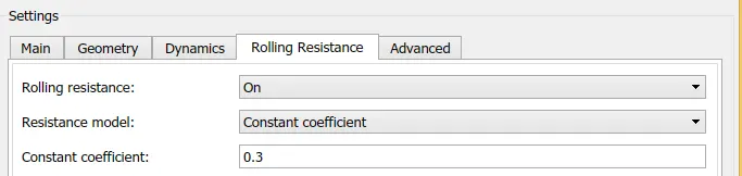
Assuming rolling coefficient: 0.3
POWER REQUIREMENTS BY THE VEHICLE CALCULATED IN THE EXCEL SHOWN BELOW:
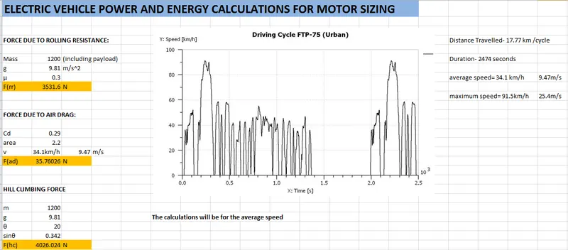
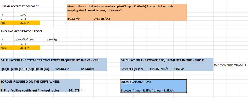
ROLLING RESISTANCE FORCE AND DRAG FORCE WILL INCLUDE PERMANENTLY TO TRACTIVE EFFORT OF THE VEHICLE WHERE AS ACCELERATION FORCE AND HILL CLIMBING FORCE REQUIRED AT SOME POINTS. KEEPING THAT IN MIND,
POWER REQUIRED BY THE VEHICLE DUE TO ROLLING RESISTANCE AND AIR DRAG :
P=3729 N * 9.47= 35 KW(APPROX)
So, keeping the other factors in mind, 100KW motor to be selected.
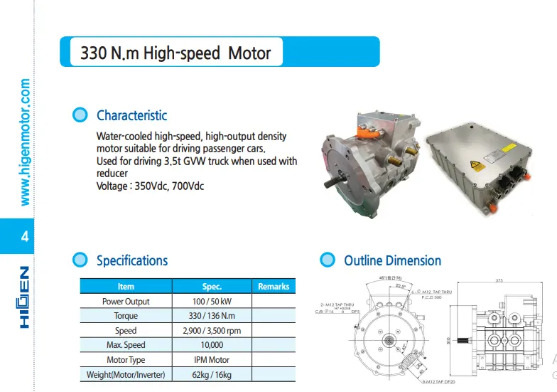
2. MOTOR CONFIGURATION
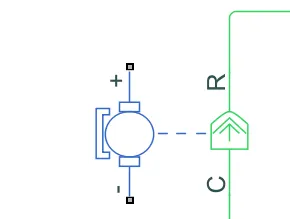
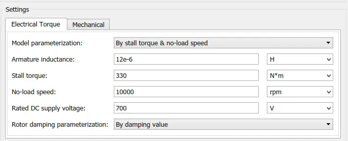
This is how the motor block looks in the simulink UI and the motor parameter values are substituted as shown below:
3. POWER CONVERTER WITH H-BRIDGE-
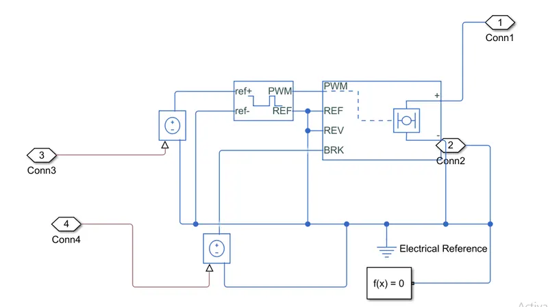
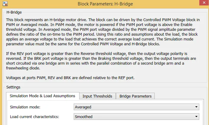
H- bridge converter is used so that which is an electric circuit that switches the polarity of the applied voltage to the load. Also, used to run DC motor forward as well as backwards. Controlled PWM Voltage is applied to the H- bridge block.
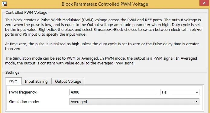
Simulation mode is set to average for both h- bridge and PWM voltage source, so that simulation time can be paced as shown below:
Similarly done for the PWM reference voltage:
4)BATTERY CONFIGURATIONS :
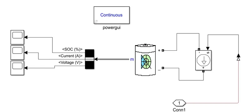
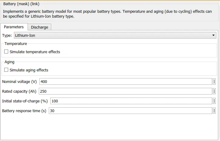
Battery capacity one of the significant factors that affects electric vehicle particularly. Low ampere hour, which is the battery capacity will result in high discharge rate and the vehicle will run for lower range. That's why ampere hour of the battery is calculated according to the motor size which equalizes 250Ah for 400V battery as shown below:
5)DRIVER CONTROLLER AND DRIVE CYCLE CONFIGURATION
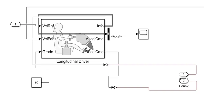
I have used a longitudnal driver block which consist of three input blocks and three output block. In input blocks, at one port drive cycle input is given and also feedback velocity input port is connected with the actual velocity block as it helps to accelerate or decelerate the vehicle.
Out port consist of acceleration and deceleration command given from the drive cycle input which feeded to the control voltage source and then to reference PWM voltage in the values ranging from 0 to 1.
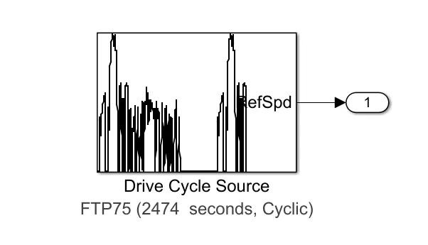
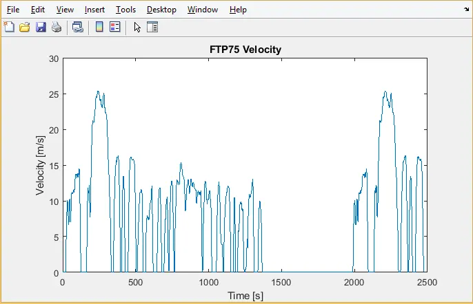
The drive cycle I used is FTP-75, which is the inbuilt in the simulink Library browser and it runs for 2474 seconds, with a distance of 17.77km and average speed of 34.1 kmph.
PLOT FROM DRIVE CYCLE SOURCE:
FULL MODEL IN SIMULINK:
RESULTS AND CONCLUSION:
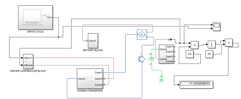
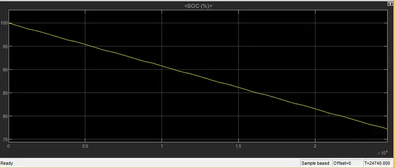
The vehicle is run for 10 cycles which equalized 24740 seconds and the state of charge reduced to approximately 77%. Also regenerative braking helps the motor to work as a generator, thus improving the state of charge of the vehicle. The vehicle run for approximate 42 km for the 10 cycles and range of the vehicle for full charge battery limits to 175km for the FTP-75 drive cycle.
1) State Of Charge Plot:
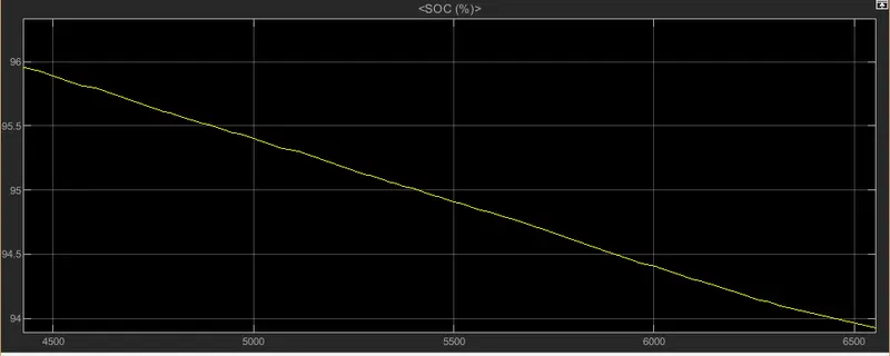
A little stability in the plot line shows the regenerative action of the vehicle, which means the vehicle is charging for that short passage.
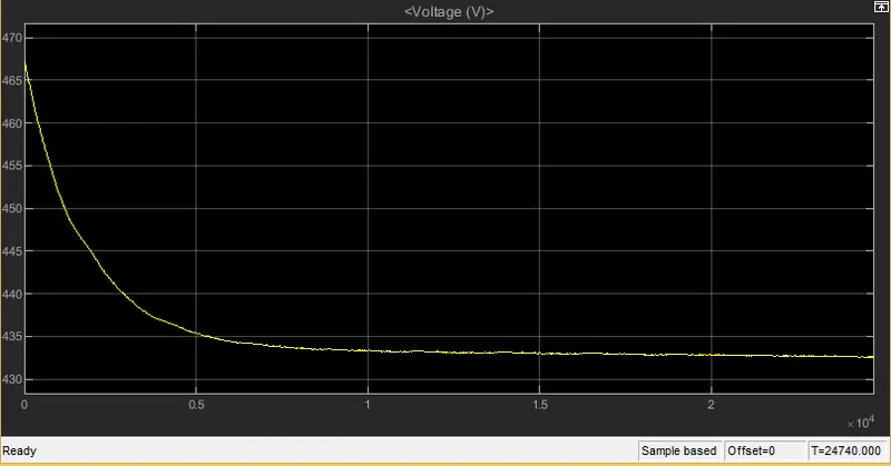
2)Voltage plot from the battery:
3) DISTANCE COVERED:
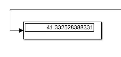
41.33 KM
The vehicle is run for 10 cycles which equalized 24740 seconds and the state of charge reduced to approximately 77%. Also regenerative braking helps the motor to work as a generator, thus improving the state of charge of the vehicle. The vehicle run for approximate 42 km for the 10 cycles and range of the vehicle for full charge battery limits to 175km for the FTP-75 drive cycle.