Final Project: Design of an Electric Vehicle
Solution:
Aim:
Create a MATLAB model of electric car which uses lithium ion battery and induction motor. Chose suitable block for powertrain block set. Prepare a report about your model including following.
Objective:
- System level configurations
- Model parameters
- Results
- Conclusion
Solution:
Electric vehicle is defined as a vehicle that uses an electric motor for the propulsion unlikely to an internal combustion engine used by conventional vehicles. EV's use electric power instead of fuels as conventional vehicles would, and because of this difference, EV donot produce any exhaust gasses or pollution.
The power needed for the operation of an EV can come from a variety of source like batteries, ganarators, etc.
MATLAB model of an Electric car which uses ithium ion battery and induction motor. Choose suitable blocks from Powertrain block set:
To model and simulate an electric vehicle with simulink.
Let us consider a model in this report, an electric vehicle with a induction motor and battery system using the SIMULINK. In modelling this EV for a drive cycle and to check performance parameters; to measure speed, SOC, and the current characterstics of its battery system etc.
Components:
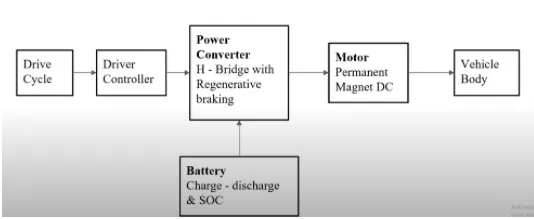
The main components of modelling an EV are:
- Vehicle body
- Motor & motor controller
- Power Converters
- Batteries
- Drive cycle
Block Diagram:
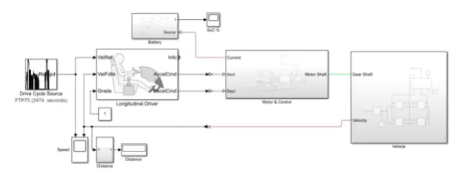
Simulink Model:
Subsystems:
> Vehicle Body:
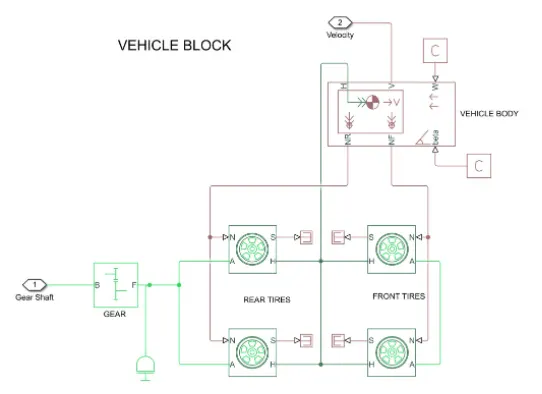
- Represents a two-axle vehicle body in motion.
- Accounts for body mass, aerodynamic drag, grade, externally defined mass and centre of gravity of the vehicle body.
Input ports:
- W - Wind Velocity in m/s
- beta - Grade angle in radians
Output ports:
- V - Velocity in m/s
- NR - Normal force on Rear Axle (N)
- NF - Normal Force on Front Axle (N)
Vehicle Body Parameters:
- Vehicle body mass, Centre of gravity distance values and aerodynamic drag variables are modified.
- Pitch dynamics are kept ON with other variable value as default values.
Tires:
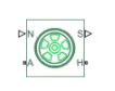
- Used to model a tire longitudinal behavior given by equation based on four fitting coefficients.
- The block can model tire dynamics under constant or variable contact surface conditions.
Input port:
- N - Normal force acting on tire, positive when force is acting downwards/towards the contact surface.
Output port:
- S - Slip value relative to tire and surface of contact.
Conserving ports:
- H - Represents wheel hub which transmits thrust generated by the wheel to the body of the vehicle.
- A - Represents axle on which the tire are mounted.
Gear:

- A simple gear block is used to connect the motor to the rear axle of the vehicle.
- It represents the gearbox which connects the input shaft to the base gear and output from the foller gear.
Conversion ports:
- B - Port associated with input shaft (motor shaft)
- F - Port associated with outout shaft (axle / differential)
Simple Gear parameters:
- Gear ratio and output direction is modified.
- Meshing loss is kept constant and gear is having a constant efficiency throughout the simulation.
- Viscous losses and faults are kept at default conditions.
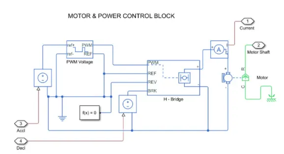
MOTOR AND POWER CONVERTER:
The motor and its control block is as shown below;
H-Bridge:
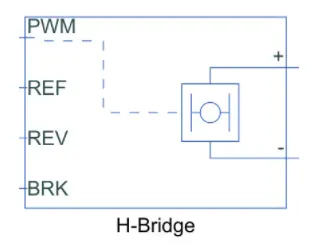
The H-Bridge helps in controlling the power that is input according to the requirement. The output provided are converted voltage s per the controlled parameters.
DC Motor:
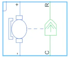
his is the DC motor which would give the rotational power to the wheels and become the sole power generation source.
The DC Motor terminals are connected as mentioned below,
+= Electrical signal to the Motor Positive Terminal
-= Electrical signal to the Motor Negative Terminal
R = Casing of the motor connected with the Mechanical Rotational Reference Block.
C = Rotor case connected to the Mechanical Rotational Reference.
The parameter considered are, the armature inductance is as default, varied the changes in the NO-Load speed @ 8000 rpm, the rated speed @ 5000 rpm, the rated load at 50 KW, and the rated DC supply voltage @ 300 V. All other parameters are as default.
Controlled PWM Voltage:
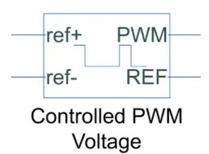
The controlled PWM Voltage Block hels in keeping the modulated Pulses as per the required Pulses. So that the operations happens smooth and higher variations are not observed.
The ports are connected as follows,
ref+= Reference Positive connected with the acceleration commands from the driver model
ref-= Reference Negative connected with the Deceleration commands from the driver model
PWM = PWM connected directly to the H-Block
REF = REF connected directly to the H-Block
Battery source:
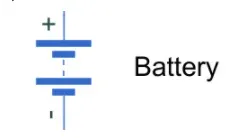
The battery is connected as the power source to the model so that the power coud be generated and the same power is transmitted accordingly to all the operating sources.
The terminals connected are to,
+= The positive terminal of the operating sources
-= The negative terminal of the operating sources.
Components of battery block:
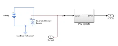
The parameters considered of th battery are;
The battery Nominal Voltage is rated as pr 300 volts,
The internal resistance is as per 0.5 Ohms and other set as default.
Driver Model:
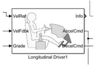
The driver model has the input and output ports which are connected to the following.
Velocity Reference = Drive cycle
Velocity Feedback = Distance Calculation
Grade = Constant 0
Info = Not connected
Acceleration Command = Controlled PWM Source
Deceleration Command = Brake in H-Bridge to maintain the speed according to the Drive Cycle
Drive Cycle:
Starting with the drive cycle,let us consider a WOT Drive cycle for the operation of the cycle in which the test duration would be 60 seconds.
Outputs:
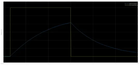
The model with the above details is simulated and the results are as follows:
1]. The Velocity Feedback and the Drive Cycle Source:
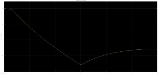
2]. Battery SOC: