Final Project: Design of an Electric Vehicle
1.ELECTRIC VEHICLE :
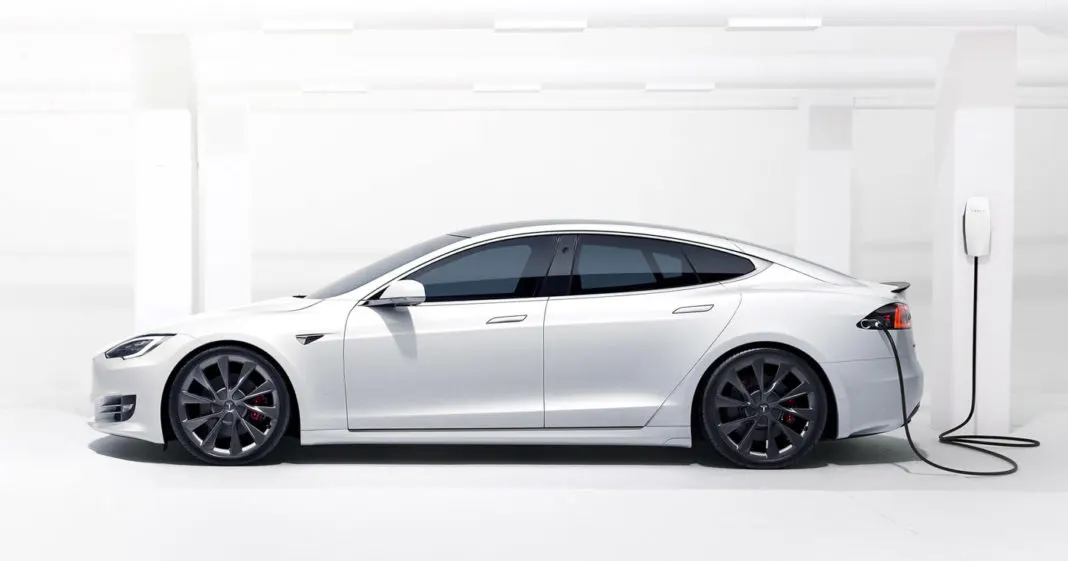
A vehicle(automobile) which uses only battery as a source to propell the vehicle and auxillary purpose is said to be an pure electric vehicle.which consists of diffrent (major) parts like
- vehicle body
- motor
- motor controller
- battery
- On board charger
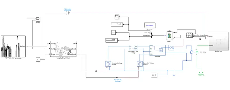
SIMULINK MODEL OF AN ELECTRIC VEHICLE :
This is the simulink model of an simple electric vehicle which uses a dc motor and its controll circuits is depicted below.
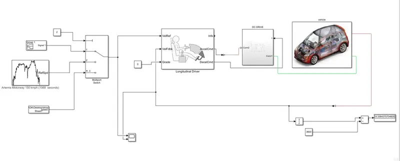
Simplified model with subsystem blocks shown below :
The main two subsystem are mentioned here are
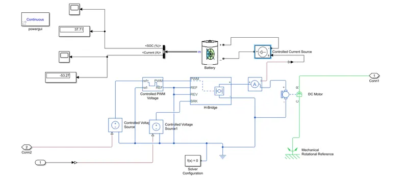
Dc drive : It consists of motor and its controller
vehicle body : tires and chassis of EV.
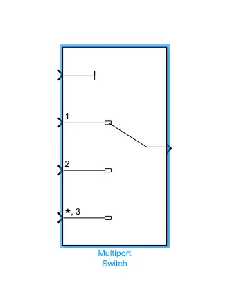
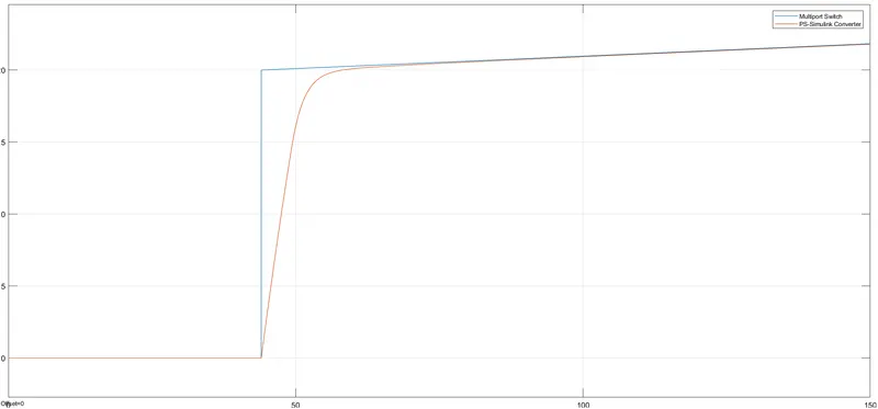
The multiport swich for diffrent drive cycles in one model.
Objectives:
1. System level configurations :
The below blocks are used in configure the system model :
1.Drive cycle source
2.multiport switch
3.Longitudinal Driver
4.dc drive
5.vehicle body
6.controlled voltage source
7.controlled current source
8.battey
9.ps to simulink and simulink to ps blocks
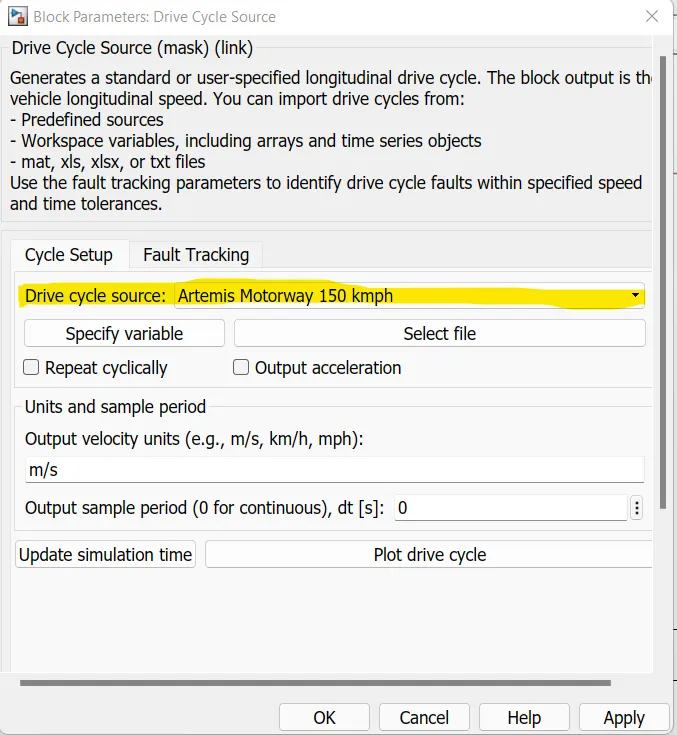
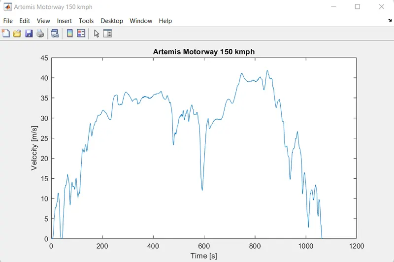
1.Drive cycle source :
2.multiport switch :
Select output signal based on control signal
3.Longitudinal Driver :
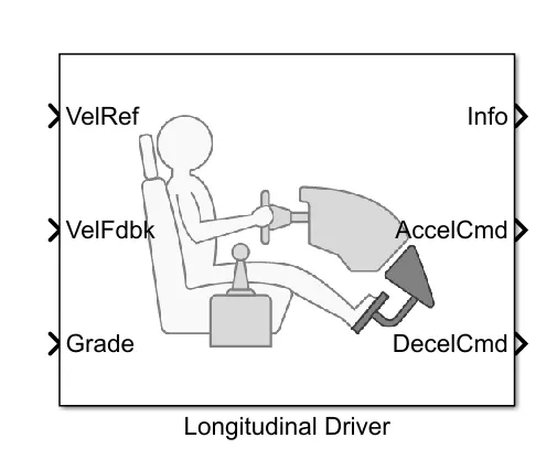
The Longitudinal Driver block is similar to a driver . Based on reference and feedback velocities, the block generates normalized acceleration and braking commands that can vary from 0 to 1. You can use the block to model the dynamic response of a driver or to generate the commands necessary to track a longitudinal drive cycle.
The block consists of inputs like ;
Reference velocity ,
Feedback velocity , and
Grade
The block consists of ouputs like ;
accelaration command
deceleration command
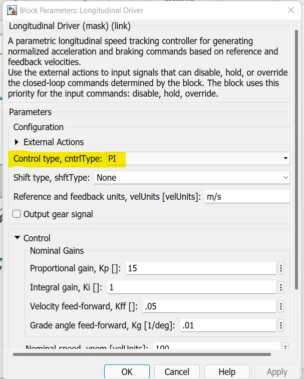
We can modify the different controller inside the longitudinal driver block by modifying controll type which is highlited in the image.
4.Dc drive :
The name drive means motor + controller
The motor used in this model is Dc motro and its controller that's why it is known as Dc drive.
The model inside the drive is shown below
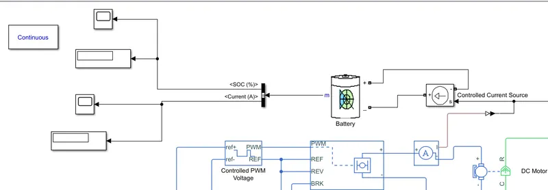
This block also consists of battery soc measuring circuit.The circuit is built with help of controlled current source ,battery.
5.vehicle body :
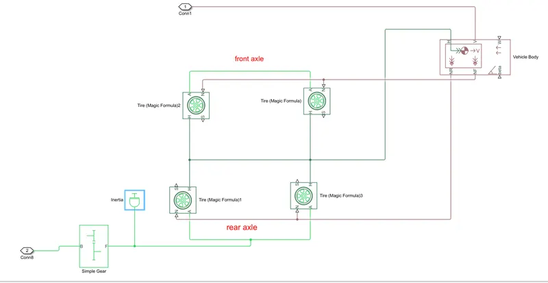
The vehicle body is nothing but the chassis and wheels of the vehicle.
The vehicle body model consists of parts like ;
1.Tires (4nos)
2.Vehicle body
3.Simple gear
4.inertia.
1.Tires :
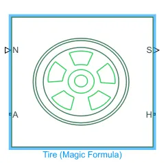
The model developed for a 4 wheeler so it consists of 4 tires.
The block consists terminals like N,A,H,S
ie, N-normal force on respctive wheel
A-axle
H-tire hub
S- The tire slip
We can impliment different parameters like rolling resistance ,slip of the tires by entering into the tire block.
2.Vehicle body :
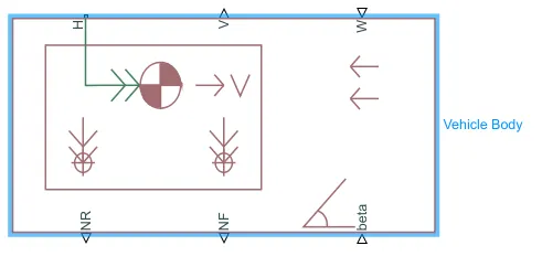
The Vehicle Body block represents a two-axle vehicle body in longitudinal motion. The vehicle can have the same or a different number of wheels on each axle. For example, two wheels on the front axle and one wheel on the rear axle. The vehicle wheels are assumed identical in size.
We can manage vehicle body mass, aerodynamic drag, road incline,frontal area of the vehicle and weight distribution between axles due to acceleration and road profile by using this block.
H-hub coneection
NR-Normal force for rear wheel
NF-Normal force for front wheel
Beta -vehicle angle wrt road.
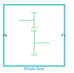
3.Simple gear :
Represents a fixed-ratio gear or gear box. No inertia or compliance is modeled in this block.
Connections B (base) and F (follower) are mechanical rotational conserving ports.
Specify the relation between base and follower rotation directions with the Output shaft rotates parameter.
we can give the desired gear ratio inside the block, and also we can change the axle direction.
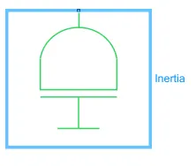
4.Inertia :
The block represents an ideal mechanical rotational inertia.
The inertia value is set as default one.
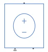
6.controlled voltage source :
The Controlled Voltage Source block represents an ideal voltage source that is powerful enough to maintain the specified voltage at its output regardless of the current flowing through the source.
The output voltage is V = Vs, where Vs is the numerical value presented at the physical signal port.
The block has one physical signal input port and two electrical conserving ports associated with its electrical terminals.
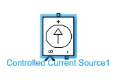
7.controlled current source :
The Controlled Current Source block converts the Simulink input signal into an equivalent current source. The generated current is driven by the input signal of the block. The positive current direction is as shown by the arrow in the block icon.
8.Battey :
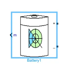
The Battery block implements a generic dynamic model that represents most popular types of rechargeable batteries.
We can modify the type of battery and battery parameters by entering inside the block .
These type of battery provides the battery soc and current ,voltage simply by selcting the bus selector.
The battery SOC is measured using this battery by simply :
9.PS to simulink and simulink to PS blocks :
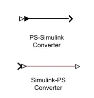
These two blocks are used to convert one form of signal into another form of signal .
PS to simulink : It converts input physical signal into simulink output signal.
simulink to PS : It converts simulink output signal into physical signal output.
10.scope & display :
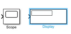
Scope used to plot the input and output signals.
Display is used to display the instant values.
2. Model parameters :
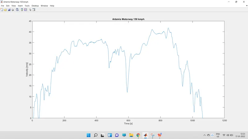
DRIVE CYCLE :
Drive cycle -artemis motorway 150kmph.
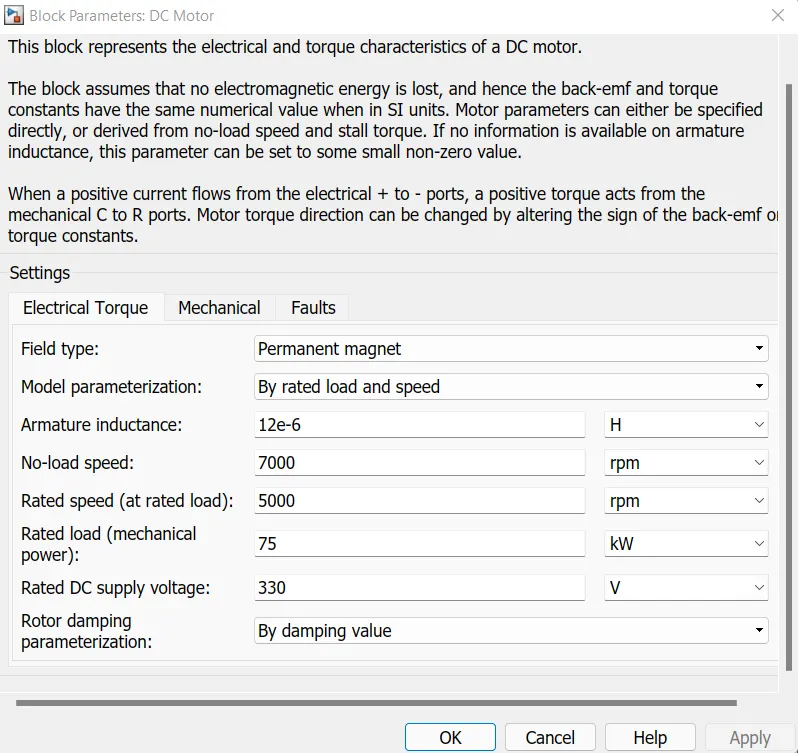
MOTOR PARAMETERS :
motor parameterization is set to rated power and load &speed .
No load speed -7000RPM
Rated speed -5000RPM
Rated load -75kw
supply voltage-330v
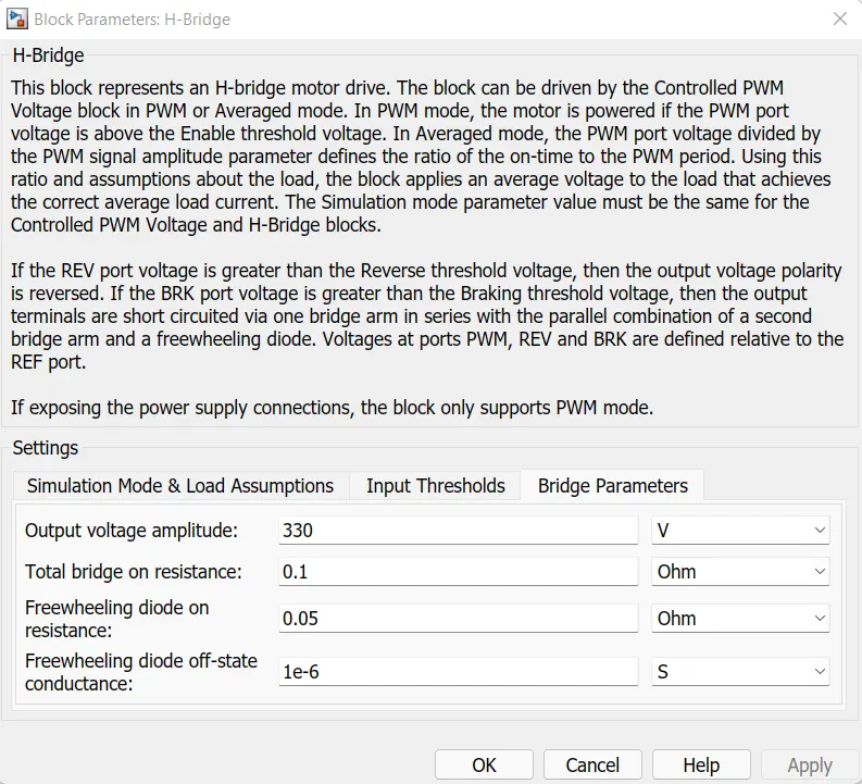
H-bridge :
output voltage -330v
Simulation mode set to - AVG value to reduce the run time.
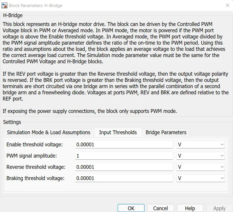
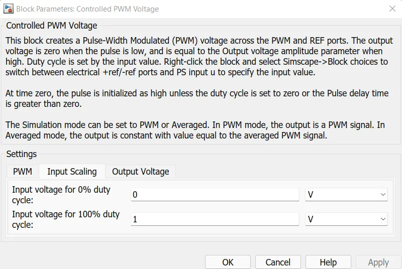
Controlled pwm voltage :
As the signals from the controlled source is like ' 0 to 1 ' from longitudinal driver the controlled pwm is set as below
simulation mode is set to avg mode for faster run time.
output voltage =1v.
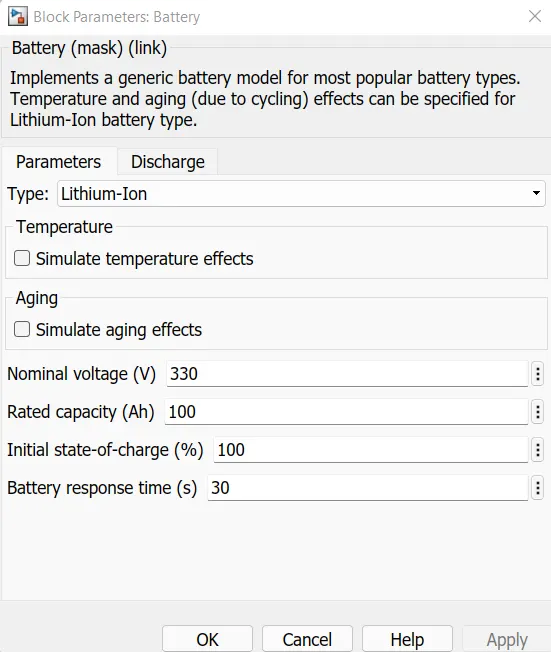
Battery :
Nominal voltage= 330v ie, simiar to rated vaoltage of motor.
AH capacity=100Ah
Intial soc =100%
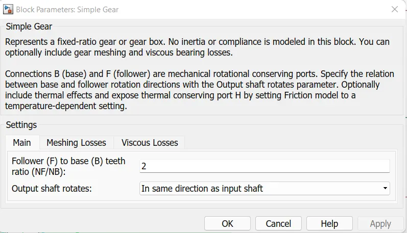
Simple gear :
shaft rotation set same direction of motor shaft .
gear ratio =2
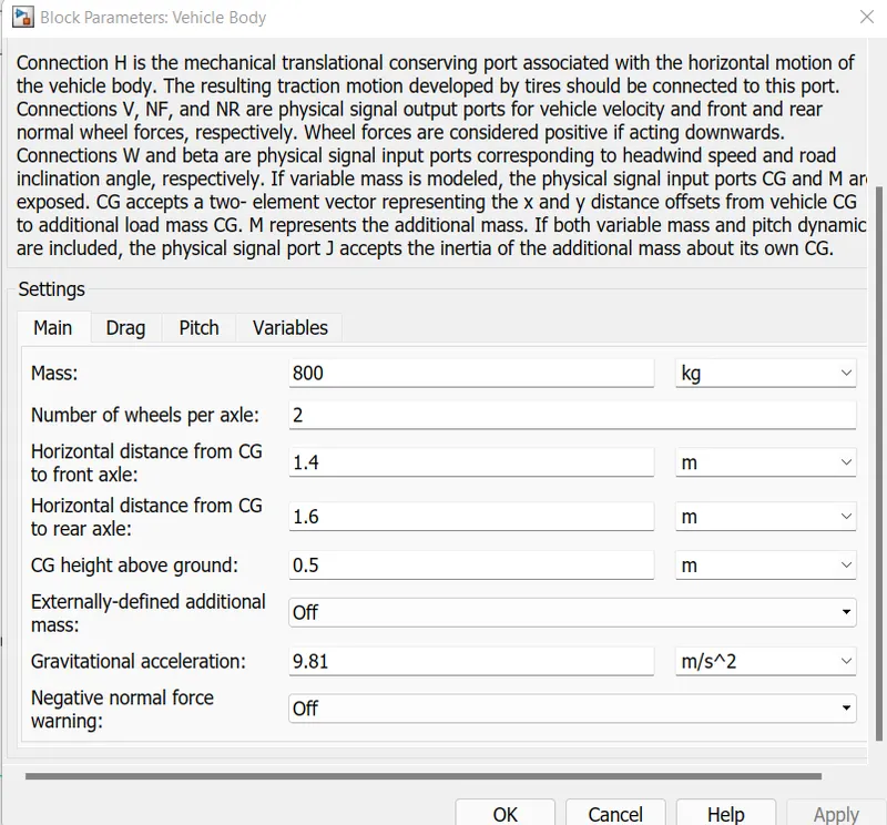
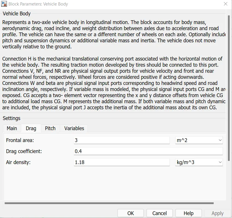
Vehicle body :
we can modify the karb weight and airdrag parameters from this block
mass=800kg
g=9.81kg/m^2
frontal area=3m^2
air density =1.18kg/m^3
drag coefficient=0.4
Tire :
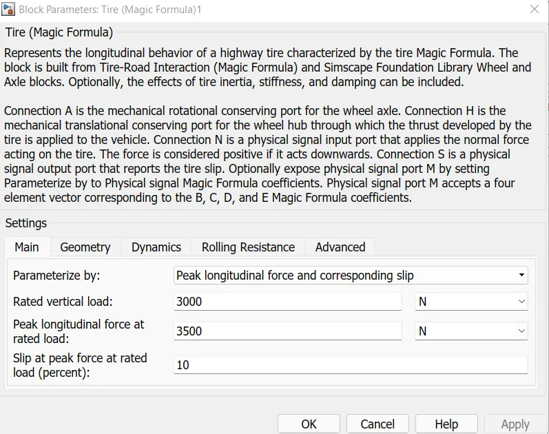
We can modify the tire slip and rooling resistance parameters from this block itself.
The following are the input parameters of the tire block.
3. RESULTS :
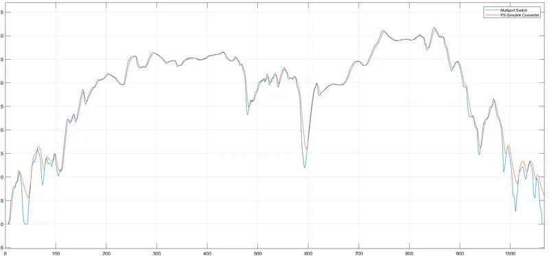
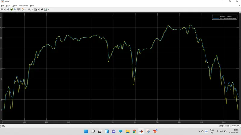
DRIVE CYCLE AND VEHICLE VELOCITY PLOT :
The drive is the reference plot and vehicle velocity is actual velocity attained by the vehcle as per the designed parameters.
The actual vehicle velocity almost follow the reference speed (drive cycle).ie, shown in the plot below.
When signal builder is set as drive cycle :
For small drive cycle ie, about 150sec of time .
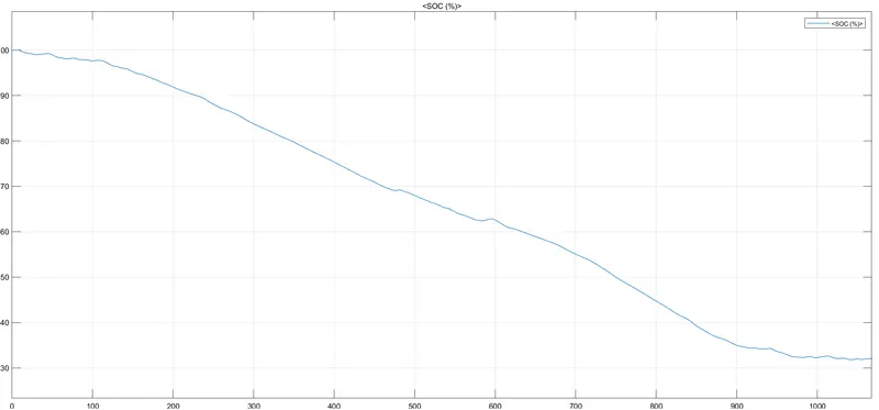
BATTERY SOC PLOT :
The battery soc drops to around 32% from 100% for the given drive cycle , with given input battery specifications.
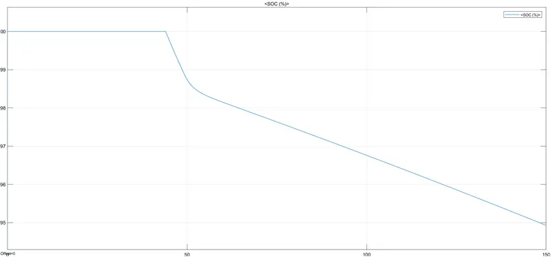
When the signal builder is set as drive cycle the soc plot is given below :
The battery soc drops to around 95% from 100% for the given drive cycle , with given input battery specifications.
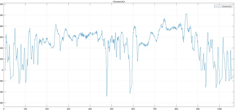
BATTERY CURRENT :
The battery or the motor current oscillates between negative and positive values ie, it reaches to peak in positive during acceleration.
It reaches to negative values during decelaration ie, known as regenarative braking .
The peak postive current is around 508A
The peak negative current is around -237A
Based on the design motor and drive cycle.
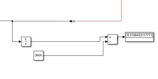
Distance travelled by the vehicle for given drive cycle :
By integrating the velocity over time is the distance covered by the vehice and diveided by time gives the actual distance in given time .
The vehicle travelld around 8.3miles in a given drive cycle time.
DESCRIPTION :
The drive cycle is the reference speed or the speed which is requied to attain by the vehicle.
The longitudinal driver is similar like a man driving the vehicle , it compares the feedback speed with reference speed if the feedback is more than reference it decelerates the vehicle ,if it is less then accelerates the vehicle.
The longitudinal driver produces the signals interms of 0 to 1.
The controlled voltage sources produce the voltages wrt to accleration and decelaration commands.
The pwm produces the respaective signal to motor based on the driver commands.
The motor rotates according to the driver commands .
The motor current and soc are calculated based on the change in vehicle speed .
Based on these controlls the vehicle propells or delcelarates .
During acceleration the motor draws the current from supply.
During decelaration the motor acts as a generator and battery soc is incresed .
The input parameters and other parametrs can be modified by entering into respective block is avilable.
CONCLUSION :
From the above results
We can design the diffrent models of EV's using diffrent simulink blocks likes motors and their controllers etc in simulink matlab tool.
It possible to run the models for diffrent default drive cycles and also for our own designed drive cycle.
we can estimate the battery capacity and also possible to observe the soc of battery for the EV .
We can modify the diffrent force effecting parametrs for the EV.
We can observe how the motor current is oscillating .
From, above all data we can conclude that , we can't get exact realtime results but we can get nearly accurate results by the simulation.