Week -2
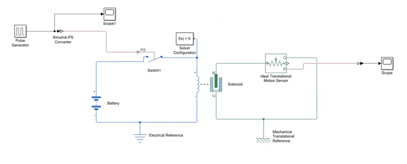
1.SIMULINK MODEL OF DOOR BELL USING SOLENOID BLOCK :
SIMULINK BLOCK DIAGRAM :
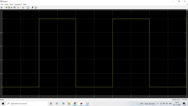
PULSE GENERATOR OUTPUT PLOT :
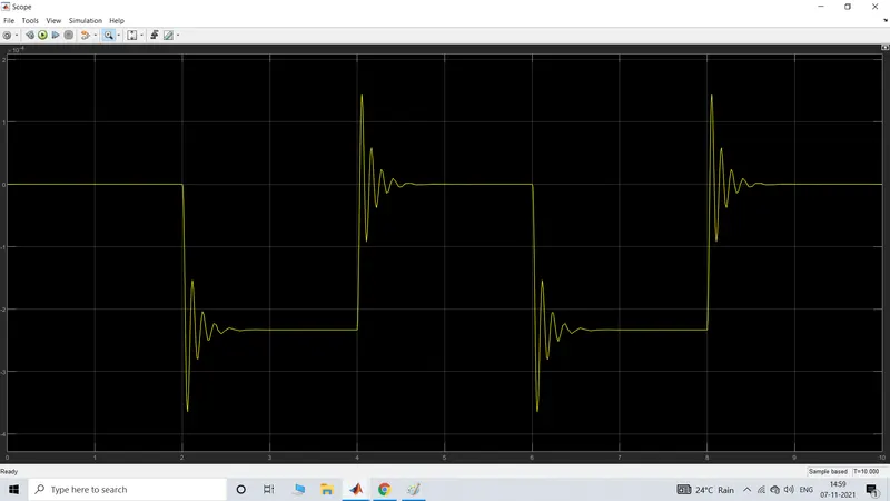
SCOPE OUTPUT :
PHYSICAL MOVEMENT OF THE PLUNGER
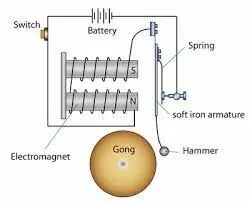
The above model represents the opertion of doorbell using a solenid.
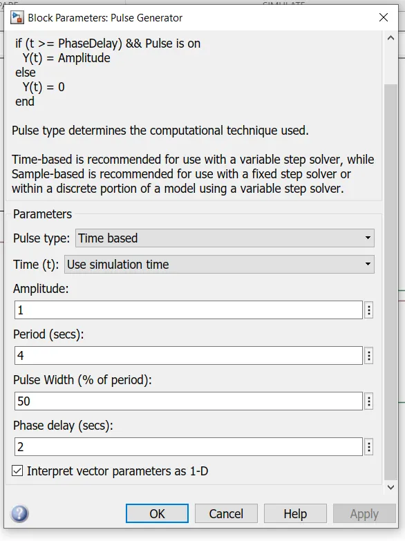
pulse generator input values:
SOLENOID:
A solenoid is a type of electromagnet the purpose of which is to generate a controlled magnetic field through a coil wound into a tightly packed helix. The coil can be arranged to produce a uniform magnetic field in a volume of space when an electric current is passed through it. or
solenoid is a device comprised of a coil of wire, the housing and a moveable plunger (armature). When an electrical current is introduced, a magnetic field forms around the coil which draws the plunger in. More simply, a solenoid converts electrical energy into mechanical energy.
Pulse generator :
Pulse generator generates square wave pulses at regular intervels of time.The block waveform parameters, Amplitude, Pulse Width, Period, and Phase delay, determine the shape of the output waveform. The Pulse Generator block can emit scalar, vector, or matrix signals of any real data type.
Battery:
battery provides the voltage supply reqired to generate the magnetic flux in the solenoid.
Simulink to ps coverter :
This block is used to convert simulink variables into physical system variables and vice versa.
Sensors :
Different sensors used to sense the physical variables like motion etc.
EXPLANATION :
The circuit mainly consists of battery,solenoid,door bell,switch,plunger,..and an electricle reference is conected to electricle circuit,and mechanicle reference is conected to mechanicale circuit.
The solenoid coil is connected to the battery supply. The switch is connected to the pulse generator .
Based on the puse inputs to the switch circuit controlled and entire operation is controlled.
The plunger moves with respect to with the given inputs. and the scope outputs are ploted.
2.THERMISTOR :
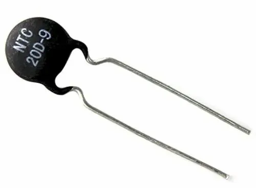
A thermistor is a resistance thermometer, or a resistor whose resistance is dependent on temperature . The term is a combination of “thermal” and “resistor”. It is made of metallic oxides, pressed into a bead, disk, or cylindrical shape and then encapsulated with an impermeable material such as epoxy or glass.
Thermistors are used as temperature sensors. They can be found in every day appliances such as fire alarms, ovens and refrigerators. They are also used in digital thermometers and in many automotive applications to measure temperature.
- Thermistor need for shielding power lines.
- Extremely non-linear.
- Passive.
- The thermistor is not suitable for a large temperature range.
- The resistance temperature characteristics are nonlinear.
- Narrow working temperature range compared to other sensors such as RTD and thermocouple.
SIMULINK BLOCK DIAGRAM :
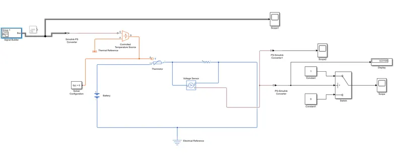
Fan controlled thermistor :
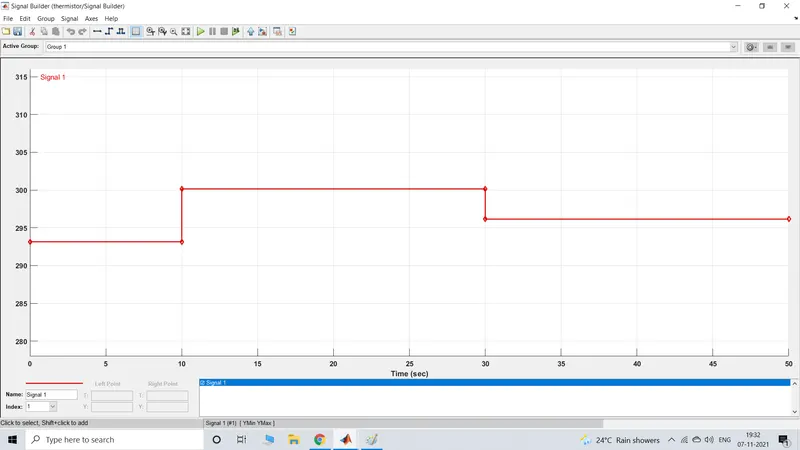
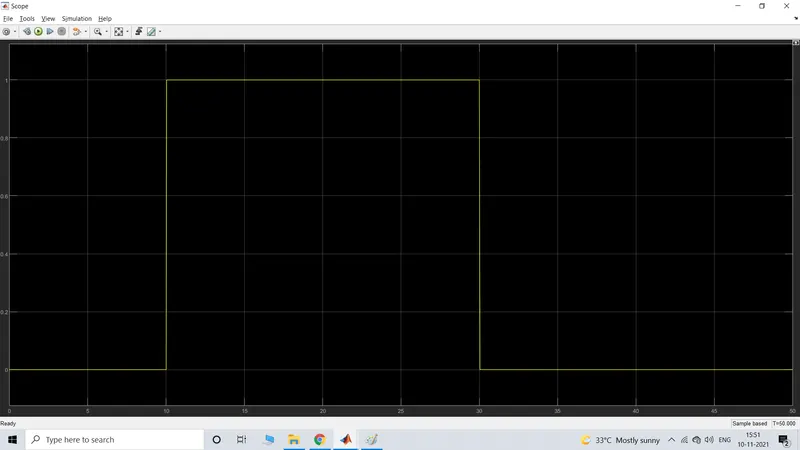
inputs: Teamprature source 20degrees celecius from 0to 10sec.27degrees celsius from 10 to 30 sec .23degrees celsius from 30 to 50 secs.
Fan conditions :On if the teamparature above 20 dgrees celsius.off otherwise.
The input signal corresponding to the above parametes is given using a single builder block.
At point 1,time=0seconds .teamprature=293.15k
At point 2,time =10 seconds,teamparature=293.15k
At point 3,time=10seconds,teamparature=300.15k
At point 4,time=30seconds,teamparature=300.15k
At point 5,time=30seconds,teamparture=296.15k
At point 6,time=50seconds,teamparature=296.15k
Simulink to ps converter modifications :
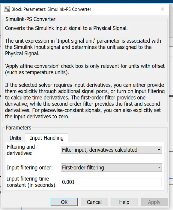
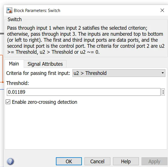
Threshold value of the switch :
- In order to know the threshold value , first we have to connect a constant block to the simulink to ps converter with 298 as input.
- And then run the simulation.
- The voltage generated in the display is enterd as the threshold to the switch.
- Then connect the signal builder again in the place of costant and run the simulation.
Final output :
- Abhishek VermaSir that you can help us we have a new student Thanks sir Abhishek Verma