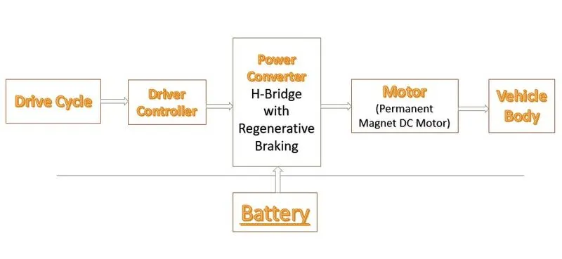
1. System level configurations
2. Model parameters
3. Results
4. Conclusion
All-electric vehicles (EVs), also referred to as battery electric vehicles, have an electric motor instead of an internal combustion engine. The vehicle uses a large traction battery pack to power the electric motor and must be plugged in to a wall outlet or charging equipment, also called electric vehicle supply equipment (EVSE). Because it runs on electricity, the vehicle emits no exhaust from a tailpipe and does not contain the typical liquid fuel components, such as a fuel pump, fuel line, or fuel tank.
Thermal system (cooling): This system maintains a proper operating temperature range of the engine, electric motor, power electronics, and other components.
Traction battery pack: Stores electricity for use by the electric traction motor.
Transmission (electric): The transmission transfers mechanical power from the electric traction motor to drive the wheels.
Architecture of Pure Electric Vehicle:-
The simplest powertrain architecture consists in a high voltage battery, an electric motor with power electronics controller and a single speed gearbox. In this vehicle the propulsion is based exclusively on the electric energy stored in the high voltage battery.
Drive cycle:-
A driving cycle is a series of data points representing the speed of a vehicle versus time. It is produced by different countries and organizations to assess the performance of vehicles in various ways, as for instance fuel consumption, electric vehicle autonomy and polluting emissions. Fuel consumption and emission tests are performed on chasis dynamometer. Tailpipe emissions are collected and measured to indicate the performance of the vehicle.
Another use for driving cycles is in vehicle simulations. More specifically, they are used in propulsion system simulations to predict performance of internal combustion engines, transmissions, electric drive systems, batteries, fuel cell systems, and similar components.
Controller:-
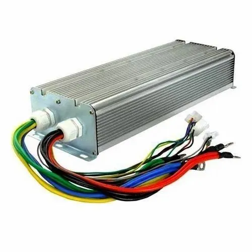
Motor controller is a combination of Power electronics and embedded micro-computing elements which make the efficient conversion of energy stored in batteries of an electric vehicle to generate motion.
Meaning of controller:- The controller is somewhat of a “middleman,” as it ensures balance and proper flow of energy within an EV. It also serves as the “brain,” as it figures out how much energy is needed by the vehicle to go smoothly on the road.
Power converter:-
A converter is an electrical circuit which accepts a DC input and generates a DC output of a different voltage, usually achieved by high frequency switching action employing inductive and capacitive filter elements.
It is an electrical circuit that changes the electric energy from one form into the desired form optimized for the specific load. A converter may do one or more functions and give an output that differs from the input. It is used to increase or decrease the magnitude of the input voltage, invert polarity, or produce several output voltages of either the same polarity with the input, different polarity, or mixed polarities such as in the computer power supply unit.
The DC to DC converters are used in a wide range of applications including computer power supplies, board level power conversion and regulation, dc motor control circuits and much more.
Battery:-
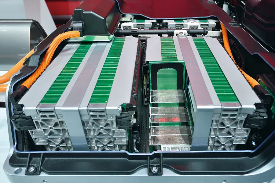
An electric-vehicle battery also known as a traction battery. It is used to power the electric motors of a vehicle. These batteries are usually rechargeabale batteries, and are typically lithium-ion-batteries. These batteries are specifically designed for a high ampere-hour (or kilowatt-hour) capacity.
It is differ from starting, lighting and ignition (SLI) batteries as they are designed to give power over sustained periods of time and are deep cycle batteries. Batteries for electric vehicles are characterized by their relatively high power to weight ratio, specific energy and energy density; smaller, lighter batteries are desirable because they reduce the weight of the vehicle and therefore improve its performance.
Now we goes to matlab modelling:-
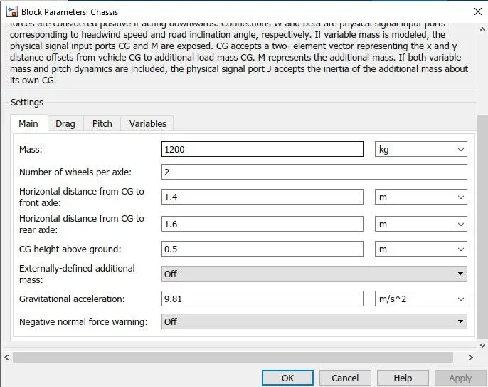
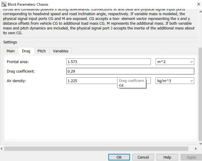
We consider the the data,
mass of vehicle:- 1200 kg,
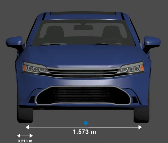
Frontal area of vehicle:- 1.573 m^2,
Drag coefficeint = 0.29,
Air density = 1.225 kg/m^3,
Number of wheel per axle:- 2.
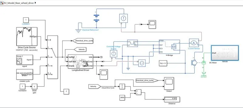
By Using Simulink system block of Electric Vehicle Design:-
Simulink Blocks are used in this model are:-
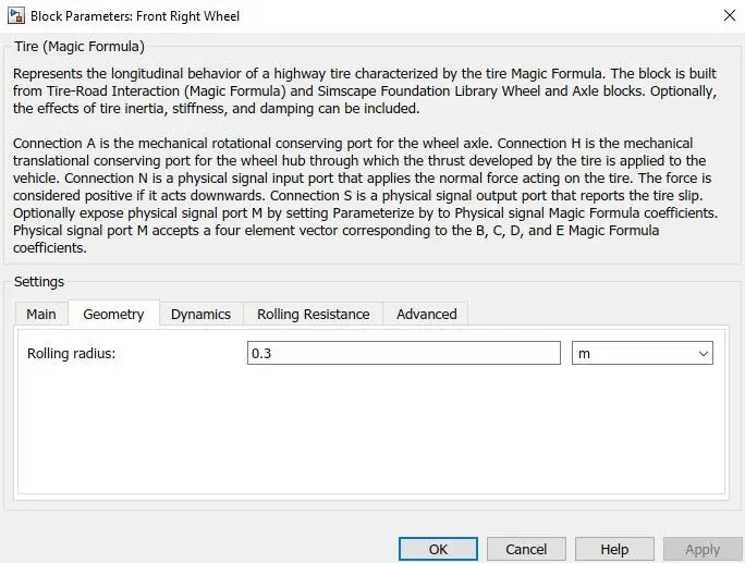
1] Tire (Magic formula)
2] Vehicle Body
3] Simple Gear
4] DC motor
5] H-Bridge Block
6] Controlled PWM Voltage
7] Controlled Voltage Source
8] Longitudinal Driver
9] Multiport Switch
10] Drive cycle source
11] Signal Builder
12] From spreadshid
13] Slider Gain
14] Constant
15] Battery
16] Electrical Reference
17] Controlled Current source
18] Terminator
19] Integrator
20] Divide
21] Cirrent sensor
22] Mechanical Rotational refernce
23] PS-simulink
24] Simulink-PS
25] PS constant
26] Solver Configuration
27] goto
28] From
Vehicle Body MATLAB/simulink:-
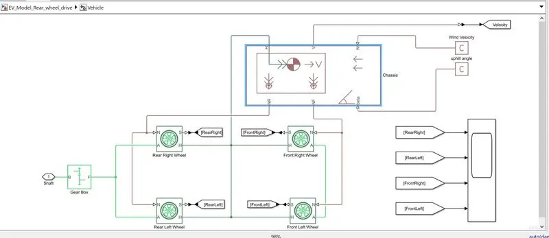
This subsystem represents as a vehicle body and it is shown below.
Starting the model calling Vehicle body block so then taking the wheels as front two tire and rear two tire connect to each other. and the rear wheel axle is connected to the simple gear block so its making a rear wheel drive vehicle.
wheel ports are,
H - Hub,
S - tire slip,
N - Normal force applied to the tire,
A - axle between two wheels
The tire hub is connected to the vehicle body H port, Rear tire force is conncetd to vehicle body NR port and same as Front tire itys connected to NF port of the vehicle body.
In this design mainly used box and their parameters:-
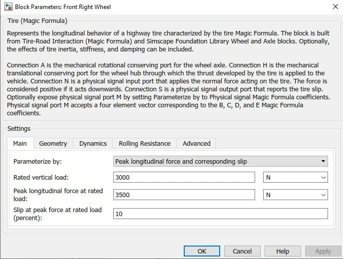
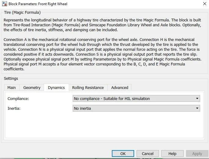
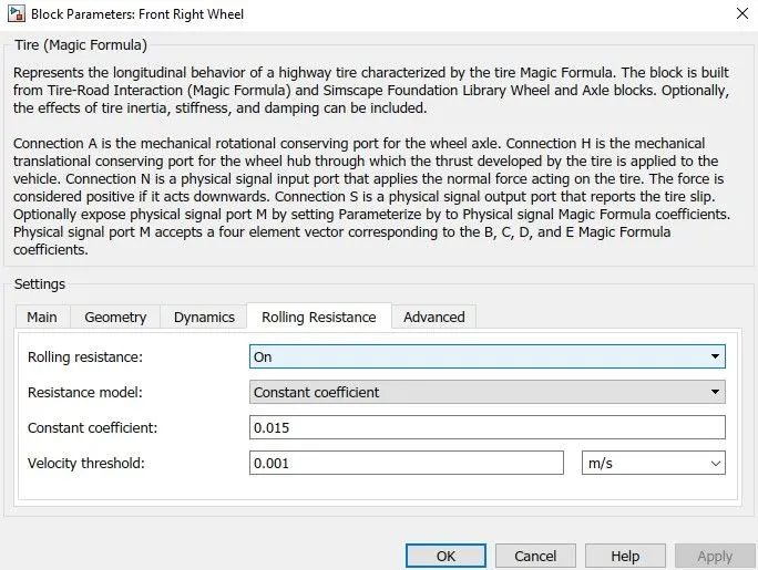
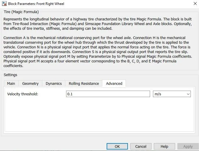
- 1] Tire (magic Formula):-
Parameters:-
The ports represented are:-
H = mechanical Hub
V = Velocity of wheel
W = wind velocity
NR = Force apllied on Rear wheel
NF = Force applied on Front wheel
beta = It is use for the velocity gradient.
Parameters:-
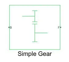
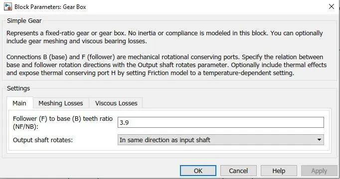
It is work as like Gearbox. Its Follower port is connected to the rear wheel axle to drive rear wheel and the base port is open to connect dc motor. In this we slected gear ratio is 3.9.
Parameters:-
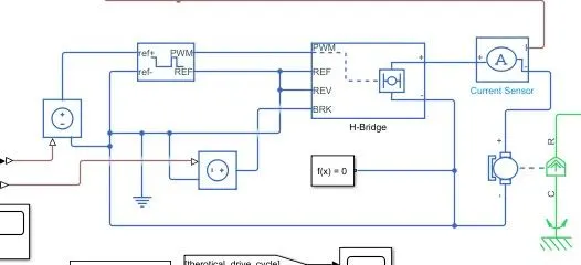
Power Control Unit:-
This system is used to create the voltage signals to control the motor speed as per the input drive cycle data.
This system is connected to the longitudinal driver block output ports namely acceleration command and deceleration command. It will convert this acceleration and deceleration command into voltage signal using two controlled voltage source block, controlled PWM voltage block, H-bridge and current sensor.
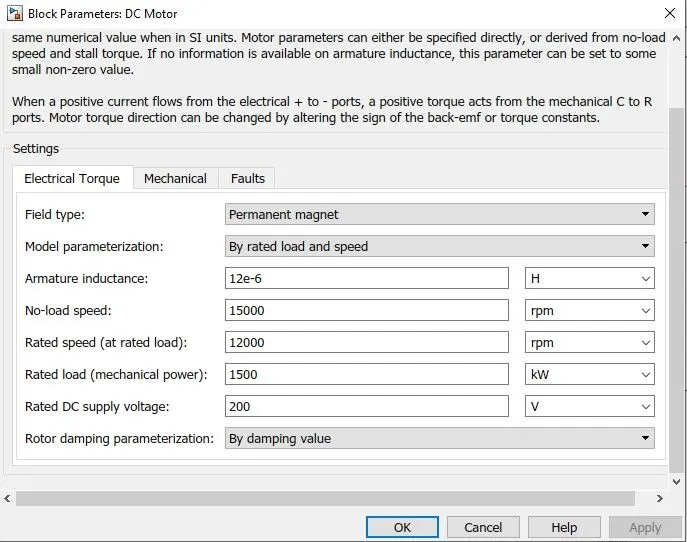
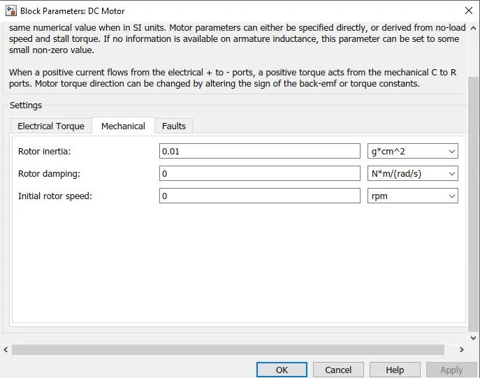
To convert the electrical energy to mechanical energy we use motor. In this electric vehicle model we have used DC motor. This motor can act as a generator also in case of regenerative braking.
The motor block and its parameters are shown below.
Parameters:-
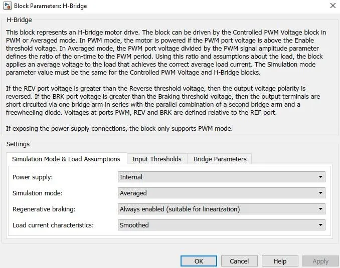
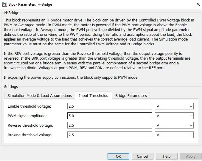
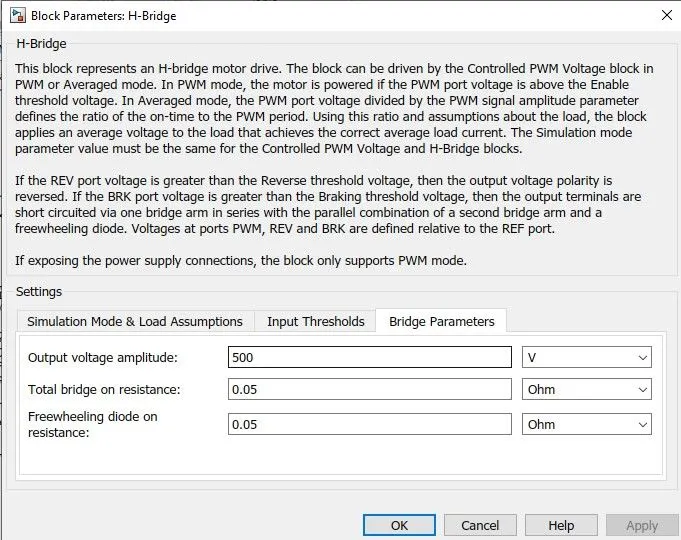
This block is used to change the polarity of the voltage applied across the DC motor so as to run the motor in forward and reverse direction as per the input command.
Parameters:-
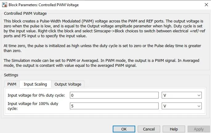
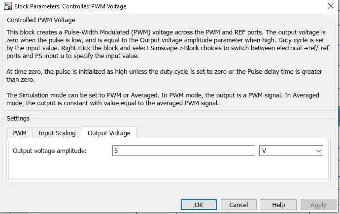
- 3] Controlled PWM Voltage block:-
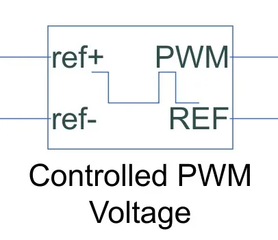
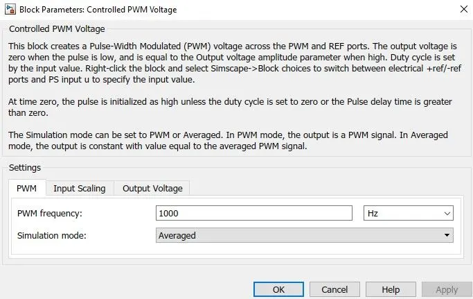
This block is used to create the pulse Width modulation (PWM) voltage.
Electrical input ports:- The block calculates the duty cycle based on the reference voltage across its ref+ and ref- ports. This modeling variant is the default. The value of the output voltage amplitude parameyter determines amplitude of the output voltage.
Parameters:-
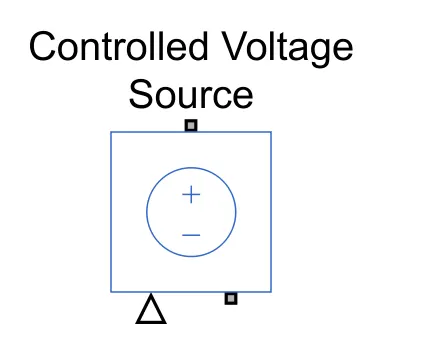
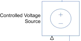
- 4] Controlled Voltage source Block:-
This block is uswed to maintain the specified voltage as its output regardless of the current flowing through the source.
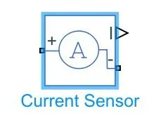
- 5] Current sensor block:-
It is used to measure the current flowing through the H-bridge.
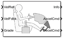
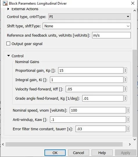
- 6] Longitudinal Driver block:-
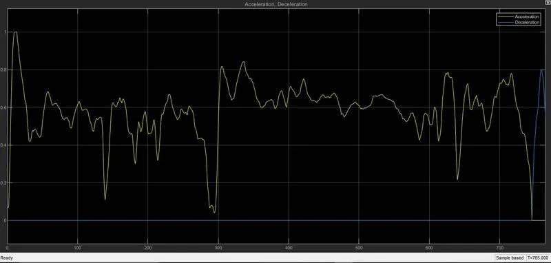
This block is used to create a longitudinal speed tracking controller and it is based on refernce and feedback velocities the blockgenerates normalised acceleration and braking command that can vary from 0 through 1. We can use this block to model the dynamic response of a driver or to generate the commands necesary to track a longitudinal drive cycle.
Parameters:-
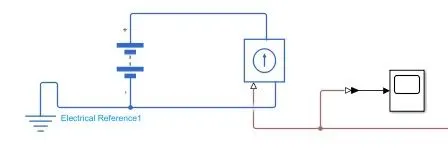
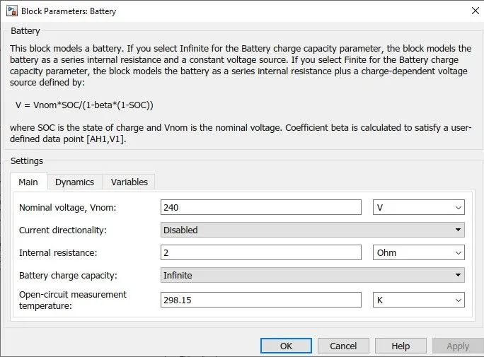
Battery design Unit:-
The battery block reprensents a simple battery model. The block models as a series internal resistance and a constant voltage source.
Parameters:-
- 2] Controlled Current source Block:-
This block is gives a contant current output regardless of voltage across it.
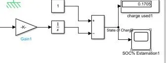
State of charge Unit:-
State of charge means it shows the how battery use and how many battery capacity is remaining.
In this Design we multiply 1/50*3600 with the current and its integrate then subtracts from 1.
In this Design we multiply 1/50*3600 with the current and its integrate then subtracts from 1.
Results:-
Using HWFET Drive cycle:-
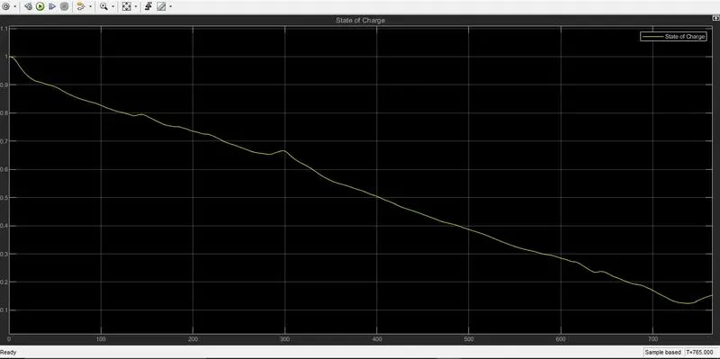
State of charge:-
In this shows the nearly after 10-15 sec the battery starts the decresing and continuously goes to decrease and the some points it will be recgarged becaused the regenertaive braking effect. the battery charging is used nearly 85%.
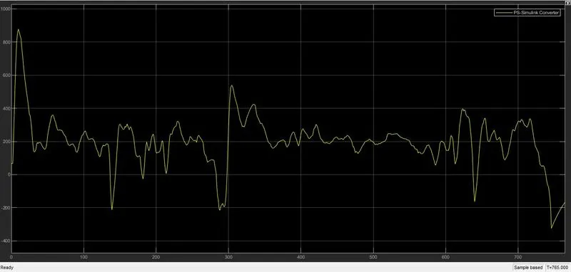
Current Voltage:-
As we see in this graph the current voltage is suddenly increase at starting but it also decrease at nearly 15-16 sec then it continuously range of 400 A. As we see the maxm current voltage at normal driving condition is nearly 550 A. and during regenerative braking the current voltage is at 200 A.
Acceleration And Deceleration by driver:-
Tire slip:-
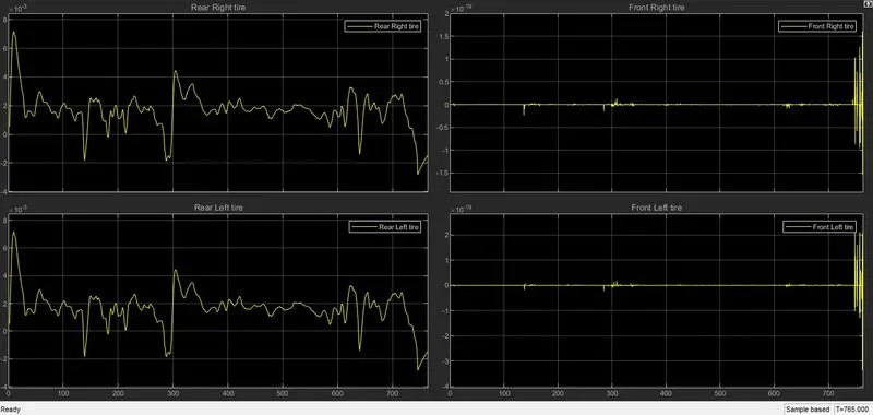
In Rear right and left wheel more slippage is oocur comparing to the front right wheel and left wheel. because the vehicle is rear wheel drive vehicle so its more occuring in rear wheels.
Theoretical and actual Drive Cycle:-
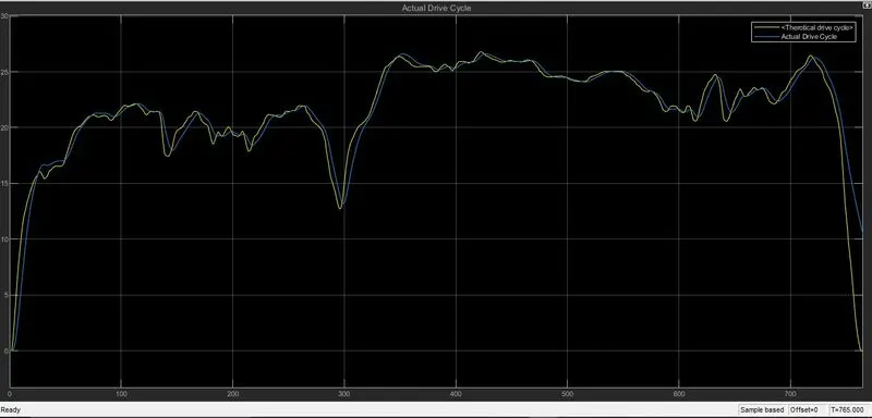
As u see in this graph the yellow line graph is HWFET drive CYcle and tye blue is the actual drive cycle. using this drive cycle as we see the actual vehicle also goes as nearly same to HWFET drive cycle and the distance also covered same.
HWFET drive cycle = 16.51KM
Actual drive cycle = 16.63 KM
Conclusion:-
Making this model i understood all parameters like Speed, SOC, Current etc with various drive cycles. and also Know how to make simple Vehicle model and how to run it in low time using individual components model.
Thank you
Dharmesh Bonde...