Final Project: Design of an Electric Vehicle
What is an Electric vehicle?
Electric vehicles (EVs) use electricity as their primary fuel or to improve the efficiency of conventional vehicle designs. EVs include all-electric vehicles, also referred to as battery electric vehicles (BEVs), and plug-in hybrid electric vehicles (PHEVs). In colloquial references, these vehicles are called electric cars, or simply EVs, even though some of these vehicles still use liquid fuels in conjunction with electricity. EVs are known for providing instant torque and a quiet driver experience. Other types of electric-drive vehicles not covered here include hybrid electric vehicles, which are powered by a conventional engine and an electric motor that uses energy stored in a battery that is charged by regenerative braking, not by plugging in, and fuel cell electric vehicles, which use a propulsion system similar to electric vehicles, where energy stored as hydrogen is converted to electricity by the fuel cell. All-electric vehicles typically have shorter driving ranges per charge than conventional vehicles have per tank of gasoline.PHEVs use batteries to power an electricmotor and use another fuel, such asgasoline, to power a conventional engine.
EVs run on electricity alone. They are powered by one or more electric motors and a battery. The battery is charged by plugging the vehicle into an electric power source and through regenerative braking. PHEVs can travel moderate distances on electricity alone. The battery can be charged by plugging into an electric power source, through regenerative braking, and by the engine. PHEVs don’t have to be plugged in before driving. They can also be fueled solely with conventional fuel. However, they will not achieve maximum fuel economy or take full advantage of their all-electric capabilities without plugging in.
Nearly all major vehicle manufacturers have EV models available, and some have committed to transitioning to selling only EVs by 2030. Medium- and heavy-duty options are also available for fleet applications. See Considering an EV for fleet-specific considerations. Nearly all major vehicle manufacturers have EV models available, and some have committed to transitioning to selling only EVs by 2030. Medium- and heavy-duty options are also available for fleet applications. See Considering an EV for fleet-specific considerations.
The batteries are typically charged byplugging the PHEV into an electric powersource, although they can also be chargedby the conventional engine and throughregenerative braking Most new BEVs are designed to travel about 100 to 400+ miles on a fully charged battery, depending on the model. EVs are generally more expensive than their conventional counterparts. However, lower fueling and maintenance costs can make them a competitive option. For example, electric drivetrains are more efficient, making BEVs (and PHEVs operating in electric mode) more than three times as efficient. Electricity is also less expensive than gasoline or diesel on an energy-equivalent basis. Generally, all-electric vehicles produce a third of the emissions of conventional vehicles and PHEVs produce less than half, considering both air pollutants and greenhouse gases. Purchasing or installing renewable energy sources will further reduce emissions.
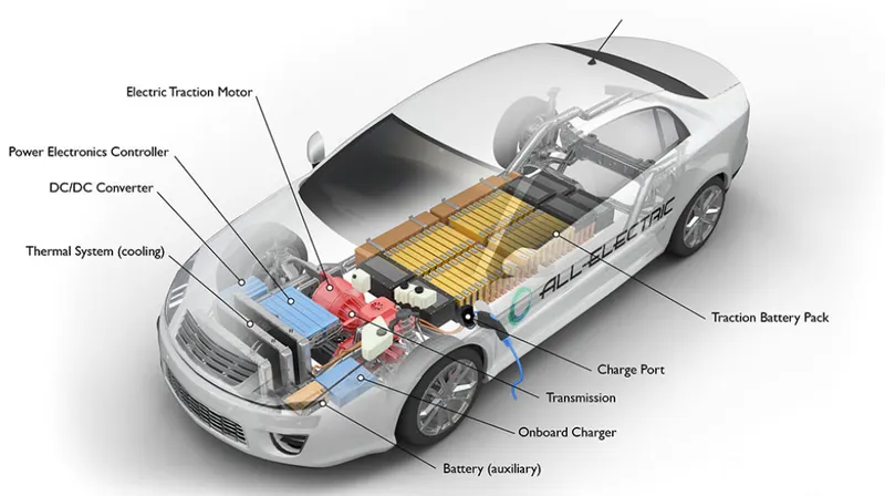
Battery (all-electric auxiliary): In an electric drive vehicle, the auxiliary battery provides electricity to power vehicle accessories.
Charge port: The charge port allows the vehicle to connect to an external power supply in order to charge the traction battery pack.
DC/DC converter: This device converts higher-voltage DC power from the traction battery pack to the lower-voltage DC power needed to run vehicle accessories and recharge the auxiliary battery.
Electric traction motor: Using power from the traction battery pack, this motor drives the vehicle's wheels. Some vehicles use motor generators that perform both the drive and regeneration functions.
Onboard charger: Takes the incoming AC electricity supplied via the charge port and converts it to DC power for charging the traction battery. It also communicates with the charging equipment and monitors battery characteristics such as voltage, current, temperature, and state of charge while charging the pack.
Power electronics controller: This unit manages the flow of electrical energy delivered by the traction battery, controlling the speed of the electric traction motor and the torque it produces.
Thermal system (cooling): This system maintains a proper operating temperature range of the engine, electric motor, power electronics, and other components.
Traction battery pack: Stores electricity for use by the electric traction motor.
Transmission (electric): The transmission transfers mechanical power from the electric traction motor to drive the wheels.
Battery-
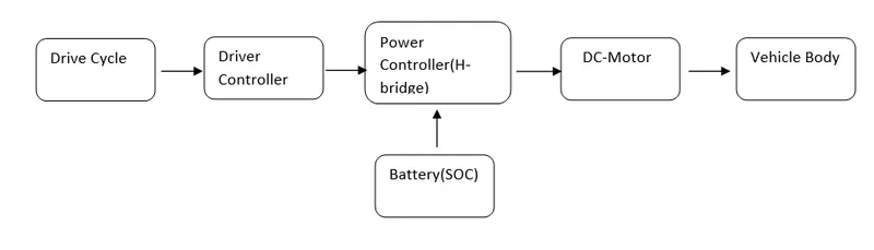
A Lithium-ion (Li-ion) battery is a type of rechargeable battery used in electric vehicles and a number of portable electronics. They have a higher energy density than typical lead-acid or nickel-cadmium rechargeable batteries. This means that battery manufacturers can save space, reducing the overall size of the battery pack.
Driver controller-
The motor drive controls the voltage that is received from the battery,The overall performance depends on the motor drive,it consist of microprocessor which regulates or delimit the amount of the voltage and current by the help of the H bridge. It helps monitor and regulates all key performance indications such as the vehicle’s operator, motor, battery, and accelerator pedal. It has a microprocessor which can limit or redirect current. It is used to either improve the mechanical performance of the car or suit the operator’s driving style. There are also more refined controllers which are capable of greater accuracy and thus, higher efficiency.
Electric Motor-
Unlike a gasoline engine with lots of moving parts, a motor only has one moving part. This makes it a very reliable source of motive power. Choosing an electric motor depends on the car’s system voltage. They can be structured to use either AC or DC current. AC motors are less expensive and lighter compared to DC motors. They are also more common and they tend to suffer from less mechanical wear and tear. However, AC technology requires a more refined or sophisticated motor controller.
Main System
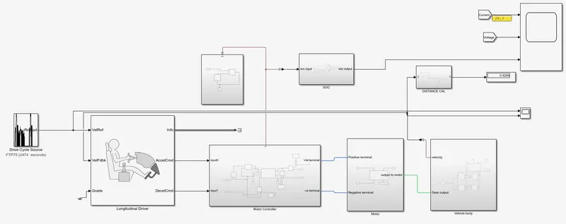
In our model,the main model consists of several subsystems,We have drive controller,Motor,Vehicle body,Battery,SoC,Longitudinal Driver,We have go through the different subsystems which constitutes,the main system,we have to look through the subsystem one by one,and describe how each blockset are connected.
Motor Control System-
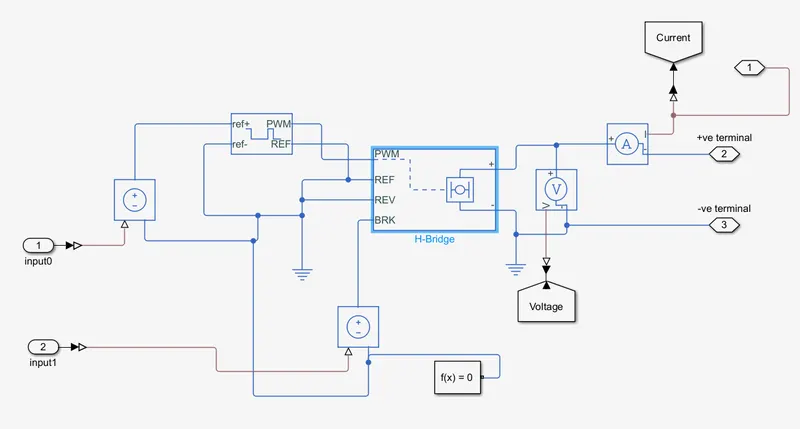
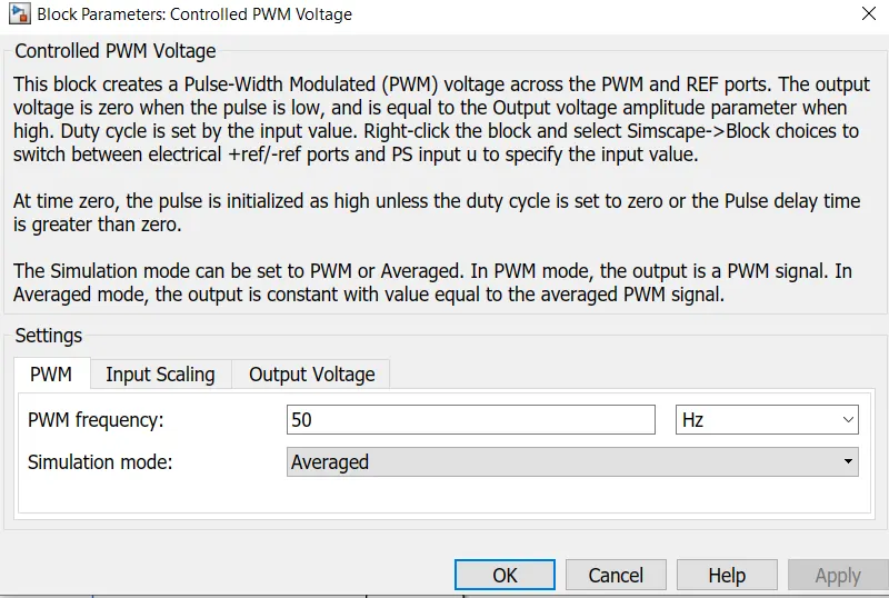
The motor control subsystem have H-bridge motor drive,. The block can be driven by the Controlled PWM Voltage block in PWM or Averaged mode. In PWM mode, the motor is powered if the PWM port voltage is above the Enable threshold voltage. In Averaged mode, the PWM port voltage divided by the PWM signal amplitude parameter defines the ratio of the on-time to the PWM period. Using this ratio and assumptions about the load, the block applies an average voltage to the load that achieves the correct average load current. The Simulation mode parameter value must be the same for the Controlled PWM Voltage and H-Bridge blocks.It have PWM port,REF reference port.
If the REV port voltage is greater than the Reverse threshold voltage, then the output voltage polarity is reversed. If the BRK port voltage is greater than the Braking threshold voltage, then the output terminals are short circuited via one bridge arm in series with the parallel combination of a second bridge arm and a freewheeling diode. Voltages at ports PWM, REV and BRK are defined relative to the REF port.In general an H-bridge is a rather simple circuit, containing four switching element, with the load at the center, in an H-like configuration.
The pwm port of the H-bridge is connected to the pwm output of the controlled pwm voltage,The reference port is grounded.And the reverse threshold voltage is also grounded.The BRK port voltage is connected to a controlled voltage source.The deceleration command from the longitudinal driver block is connected to the controlled voltage source.We have set the pwm voltage source as average for faster simulation
From the positive terminal Current sensor is attached and voltage sensor is attached to the output of the bridge block set.For
an electric circuit solver configuration is added to specify the solver parameters.The output of the voltage sensor and current sensor is connected to the goto block where we can send signals to From blocks that have the specified tag.
DC motor -
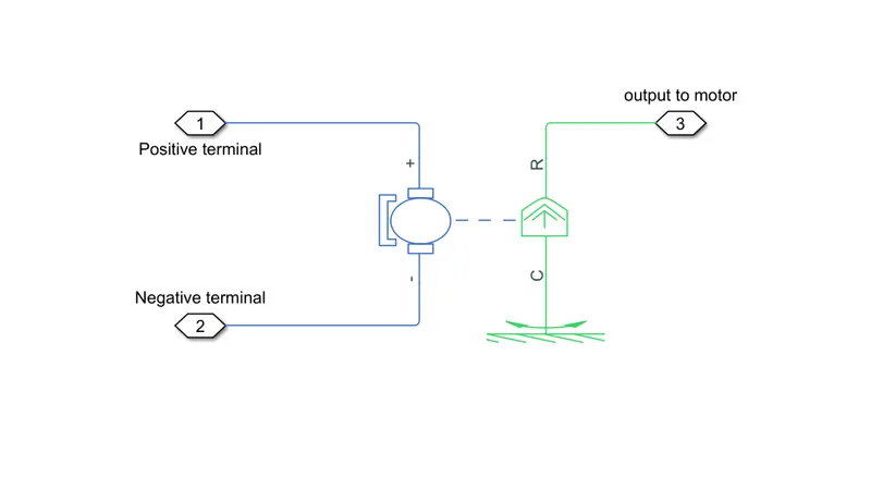
The motor used here is a field type permanent magnet dc motor,A positive torque acts from mechanical C to R port.The R port is the part which is connected to the port of the simple gear system,
The block assumes that no electromagnetic energy is lost, and hence the back-emf and torque constants have the same numerical value when in SI units. Motor parameters can either be specified directly, or derived from no-load speed and stall torque. If no information is available on armature inductance, this parameter can be set to some small non-zero value.
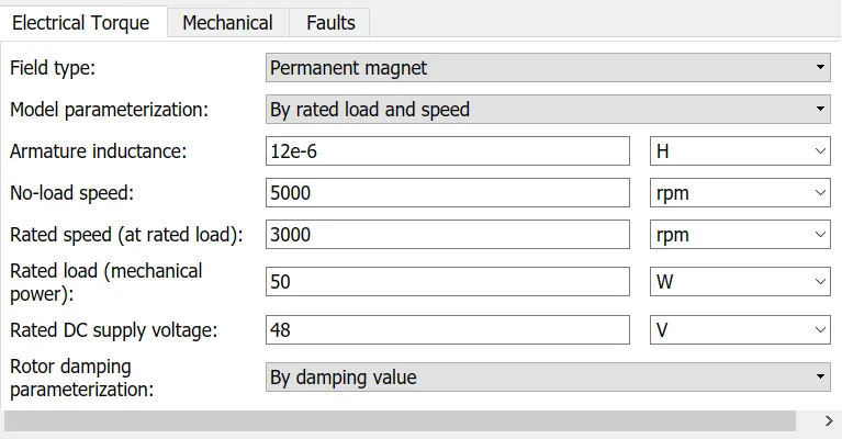
When a positive current flows from the electrical + to - ports, a positive torque acts from the mechanical C to R ports. Motor torque direction can be changed by altering the sign of the back-emf or torque constants.
The +ve and -ve terminal that are coming from the connection port of the motor controller subsystem is connected to the terminals of the motor.
Vehicle Body-
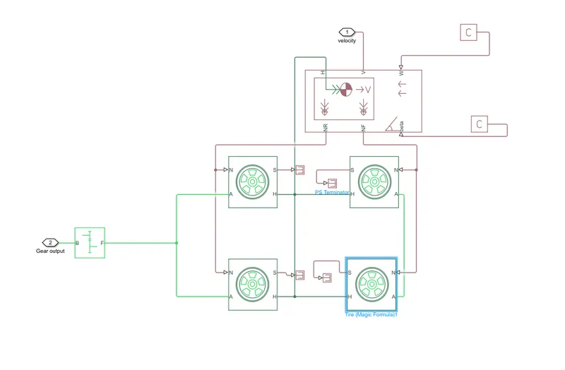
In the vehicle body subsystem,the tires with magic formula block is used,
The block is built from Tire-Road Interaction (Magic Formula) and Simscape Foundation Library Wheel and Axle blocks. Optionally, the effects of tire inertia, stiffness, and damping can be included. H port stands for the hub connected from wheels of the vehicle.That is the axle of the vehicle.We are giving power to the rear axle of the vehicle.The head wind speed
is given as a constant value,And the grade of the road beta is also given as a constant,So both of them are connected to PS constant block. 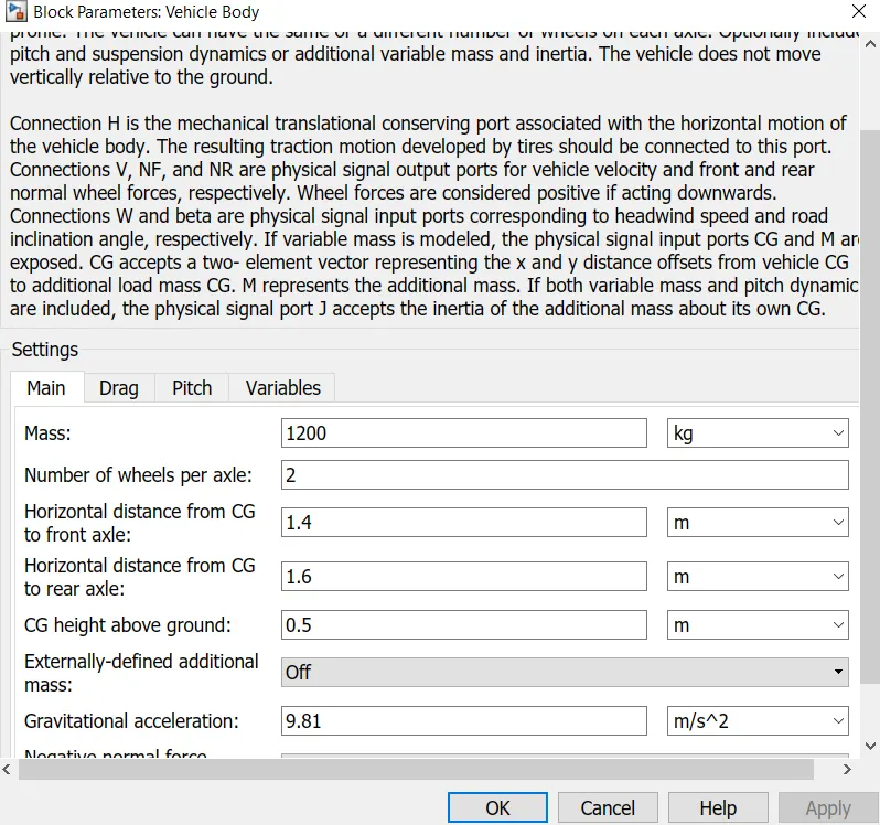
Connection A is the mechanical rotational conserving port for the wheel axle. Connection H is the mechanical translational conserving port for the wheel hub through which the thrust developed by the tire is applied to the vehicle. Connection N is a physical signal input port that applies the normal force acting on the tire. The force is considered positive if it acts downwards. Connection S is a physical signal output port that reports the tire slip. Optionally expose physical signal port M by setting Parameterize by to Physical signal Magic Formula coefficients.
The slip port are terminated by using the terminator block .The velocity port is connected to the longitudinal driver, and for distance calculation.The simple gear block is used with 2:1 gear ratio and is connected to the motor.
Battery -
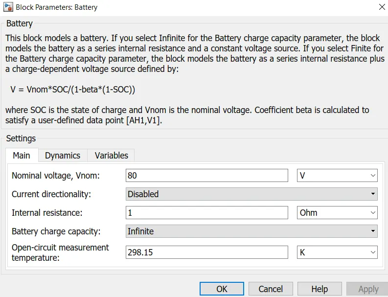
The battery used in the model is a simple battery block for faster simulation,we are having a 48V battery output voltage,
We can change the parameters of the battery block according to our specifications,
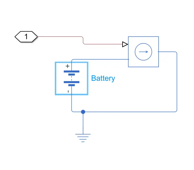
The output of the battery port is to the motor controller subsystem,
SoC susbsystem-
The SOC is defined as the available capacity expressed as a percentage of some reference, sometimes its rated capacity but more likely its current (i.e. at the latest charge).The preferred SOC reference should be the rated capacity of a new cell rather than the current capacity of the cell. This is because the cell capacity gradually reduces as the cell ages. For example, towards the end of the cell's life its actual capacity will be approaching only 80% of its rated capacity and in this case, even if the cell were fully charged, its SOC would only be 80% of its rated capacity. Temperature and discharge rate effects reduce the effective capacity even further.
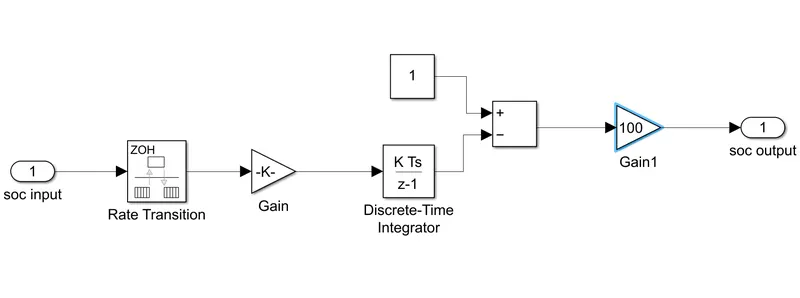
The input of SoC is taken from the battery subsystem and the output connection port to the scope.
Longitudinal Driver-
The input signals given by the user is regulated with the use of longitudinal driver.
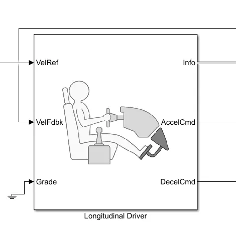
The acceleration and the deceleration feedback from the driver is generated with the help of the longitudinal driver.The block has 6 ports as Velocity reference ,The data from the drive cycle is inputed in this port and Velocity Feed back from the vehicle body is connected to this port.The grade port is grounded for simplification of the model.The acceleration and deceleration command ports that will give the recorded data and is connected to the motor controller.So the we are using a drive cycle data for inputing the speed values to the longitudinal driver.
Here we are taking FTP75 drive cycle source,
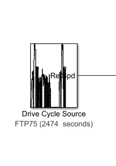
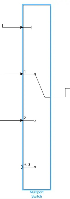
We can choose different input options for the drive cycle data,it can be from a matlab file,or from a spreadsheet,By using the multiple connection switch block we can choose the data we have opted.
For distance calculation,we have taken a formula for computing the distance travelled by the vehicle,integrator block and mathematical blocks are used for the calculation

Working -
When the simulation is started,the input from the drive cycle source is passed through the multiport switch and it is fed to the longitudinal driver as voltage reference voltage .And the drive cycle is iniated ,the voltage from is inputed to controlled voltage source blocks and to the motor controller.The acceleration feedback and deceleration feedbacks are given according to the drive cycle source signal.It is fed to the controlled controlled pwm voltage block for creating pulses according to the signal,which generates the pulses, and the H-Bridge, which accepts multiple inputs and delivers the command signal to the motor via voltage and current sensors.. According to the signals, the current and voltage fluctuation is noted.And from the motor controller the signal to the motor is initiated.And motor works w.r.t actions from the motor controller.It is connected to the transmission part where we get power to drive the wheels of the vehicle.The output is delivered in the wheels and it is also noted.The final velocity is recorded and afterwards compared to the one entered.Simultaneously, battery performance is recorded for our vehicle's efficiency. The entire performance of the vehicle over the course of 2474 seconds has been recorded.
Results-
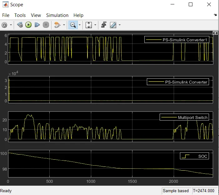
We can see the fluctuations in the voltage graph as the vehicle is moving,or with respect to the drive cycle source,During the performance of the vehicle,the FTP75 drive cycle consist of different conditions of driving with all terrain conditions,The vehicle will under go acceleration ,speeding up,deceleration,uphill condition and max speed conditon,We can see the voltage gragh fluctuates according to the pulses that the motor controller delivers and The battery conditon should be also analysed,From the SoC graph we can see there is no big change in the battery conditon,More than 90% of the battery is still remainig in the system for the drive cycle condition,The graph shows it is lowering as the time increase but not in a steep way,Also we should remember the fact that regenerative braking is also have a role in the battery system.We can see the battery drop is less when it is in the decelerating condition,than the normal condtion of the drive.So it plays a major role in the battery life of the vehicle.
Conclusion -
A simple model of an electric vehicle with given parameters is created using matlab software . Simulation was done according to the behaviour of the model and the results were analysed.