Final Project: Design of an Electric Vehicle
An electric vehicle (EV) is a vehicle that uses one or more electric vehicle for propulsion. An electric vehicle may be powered through a collector system by electricity from off-vehicle sources, or may be self-contained with a battery, solar panels, fuel cells or an electric genrator to convert fuel to electricity. EVs include, but are not limited to, road and rail vehicles, surface and underwater vessels, electric aircraft and eletric spacecraft.
EVs first came into existence in the mid-19th century, when electricity was among the preferred methods for motor vehicle propulsion, providing a level of comfort and ease of operation that could not be achieved by the gasoline cars of the time. internal combustion engwere the dominant propulsion method for cars and trucks for about 100 years, but electric power remained commonplace in other vehicle types, such as trains and smaller vehicles of all types.
In the 21st century, EVs have seen a resurgence due to technological developments, and an increased focus on renewable energy and the potential reduction of transportation's impact on climate change and other environmental issues. Project Drawdown describes electric vehicles as one of the 100 best contemporary solutions for addressing climate change.
Government incentives to increase adoption were first introduced in the late 2000s, including in the united states and the european union, leading to a growing market for the vehicles in the 2010s. Increasing public interest and awareness and structural incentives, such as those being built into the green recovery from the, is expected to greatly increase the electric vehicle market. The international energy agencysaid in 2021 that governments should do more to meet climate goals, including policies for heavy electric vehicles. Electric vehicle sales may increase from 2% of global share in 2016 to 30% by 2030.Much of this growth is expected in markets like North America, Europe and China; a 2020 literature review suggested that growth in use of electric 4-wheeled vehicles appears economically unlikely in developing economies, but that electric 2-wheeler growth is likely. There are more 2 and 3 wheel EVs than any other type.
How does charging work?
You can charge an electric vehicle by plugging it into a public charging station or into a home charger. There are plenty of charging stations around the UK to stay fully charged while you're out and about. But to get the best deal for home charging, it's important to get the right EV electricity tariff, so you can spend less money charging and save more on your bill.
EVs and their range
How far you can travel on a full charge depends on the vehicle. Each model has a different range, battery size and efficiency. The perfect electric car for you will be the one you can use for your normal journeys without having to stop and charge up halfway through. Explore our EV leasing options.
What types of electric cars are there?
There are a few different types of electric vehicle (EV). Some run purely on electricity, these are called pure electric vehicles. And some can also be run on petrol or diesel, these are called hybrid electric vehicles.
- Plug-in electric - This means the car runs purely on electricity and gets all its power when it's plugged in to charge. This type doesn't need petrol or diesel to run so doesn't produce any emissions like traditional cars.
- Plug-in hybrid - These cars mainly run on electricity but also have a traditional fuel engine so you can use petrol or diesel too if they run out of charge. When running on fuel, these cars will produce emissions but when they're running on electricity, they won't. Plug-in hybrids can be plugged into an electricity source to recharge their battery.
- Hybrid-electric - These run mainly on fuel like petrol or diesel but also have an electric battery too, which is recharged through regenerative braking. These let you switch between using your fuel engine and using 'EV' mode at the touch of a button. These cars cannot be plugged into an electricity source and rely on petrol or diesel for energy.
What are the inner parts of an EV?
EVs have 90% fewer moving parts than an ICE (Internal Combustion Engine) car. Here's a breakdown of the parts that keep an EV moving:
- Electric Engine/Motor - Provides power to rotate the wheels. It can be DC/AC type, however, AC motors are more common.
- Inverter - Converts the electric current in the form of Direct Current (DC) into Alternating Current (AC)
- Drivetrain - EVs have a single-speed transmission which sends power from the motor to the wheels.
- Batteries - Store the electricity required to run an EV. The higher the kW of the battery, the higher the range.
- Charging - Plug into an outlet or EV charging point to charge your battery.
EV batteries - capacity and kWh explained
Kilowatts (kW) is a unit of power (how much energy a device needs to work). A kilowatt-hour(kWh) is a unit of energy (it shows how much energy has been used), e.g. a 100 watt lightbulb uses 0.1 kilowatts each hour. An average home consumes 3,100 kWh of energy a year. An electric car consumes an average of 2,000 kWh of energy a year.
Electric car charging
How to charge an EV?
You can charge an electric vehicle either by plugging it into a socket or by plugging into a charging unit. There are plenty of charging stations around the UK to stay fully charged while you're out and about. There are three types of chargers:
Three-pin plug - a standard three-pin plug that you can connect to any 13 amp socket.
Socketed - a charge point where you can connect either a Type 1 or Type 2 cable.
Tethered - a charge point with a cable attached with either a Type 1 or Type 2 connector.
How long does it take to charge an electric car?
There are also three EV charging speeds:
- Slow - typically rated up to 3kW. Often used to charge overnight or at the workplace. Charging time: 8-10 hours.
- Fast - typically rated at either 7Kw or 22kW. Tend to be installed in car parks, supermarkets, leisure centres and houses with off-street parking. Charging time: 3-4 hours.
- Rapid - typically rated from 43 kW. Only compatible with EVs that have rapid charging capability. Charging time: 30-60 minutes.
Charging up in changing seasons
The weather affects how much energy your electric car consumes. You have a larger range in summer and smaller range in winter.
Charging on the go
Don't forget to download the Zap-Map app to find the nearest charge station when you're out and about.
How far can you travel on one full charge?
An EVs range is dependent on the battery size (kWh). The higher the EV battery kWh, more power, the further you travel. Here are examples of how far some electric cars charge will go:
- Volkswagen e-Golf - range: 125 miles - equivalent to a journey from Bristol to Snowdonia National Park.
- Hyundai Kona Electric - range: 250 miles - equivalent to a journey from London to the Lake District.
- Jaguar I-Pace - range: 220 miles - equivalent to a journey from Edinburgh to Birmingham
EV MODEL:-
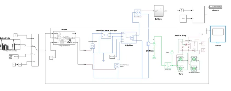
Drive cycle:-
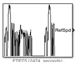
The Drive Cycle Source block generates a standard or user-specified longitudinal drive cycle. The block output is the specified vehicle longitudinal speed, which you can use to:
Predict the engine torque and fuel consumption that a vehicle requires to achieve desired speed and acceleration for a given gear shift reference.
Produce realistic velocity and shift references for closed loop acceleration and braking commands for vehicle control and plant models.
Study, tune, and optimize vehicle control, system performance, and system robustness over multiple drive cycles.
For the drive cycles, you can use.
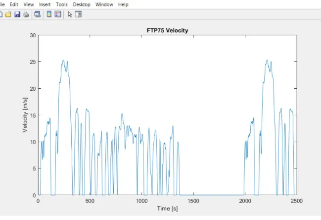
2)longitudnal drive:
+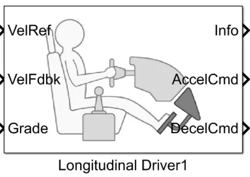
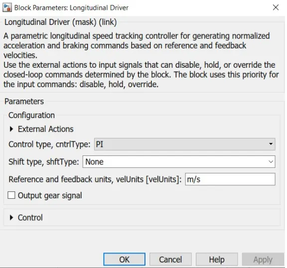
The Longitudinal Driver block implements a longitudinal speed-tracking controller. Based on reference and feedback velocities, the block generates normalized acceleration and braking commands that can vary from 0 through 1. You can use the block to model the dynamic response of a driver or to generate the commands necessary to track a longitudinal drive cycle.
Setting
Block Implementation
PI
Proportional-integral (PI) control with tracking windup and feed-forward gains.
Scheduled PI
PI control with tracking windup and feed-forward gains that are a function of vehicle velocity.
Predictive
Optimal single-point preview (look ahead) control model developed by C. C. MacAdam1, 2, 3. The model represents driver steering control behavior during path-following and obstacle avoidance maneuvers. Drivers preview (look ahead) to follow a predefined path. To implement the MacAdam model, the block:
Represents the dynamics as a linear single track (bicycle) vehicle
Minimizes the previewed error signal at a single point T* seconds ahead in time
Accounts for the driver lag deriving from perceptual and neuromuscular mechanisms.
3) H-bridge:
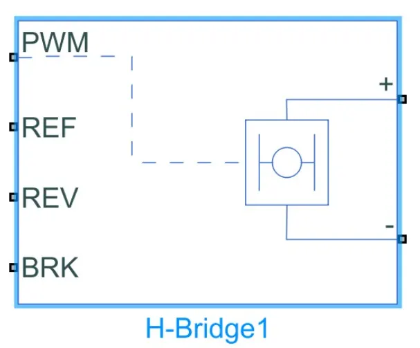
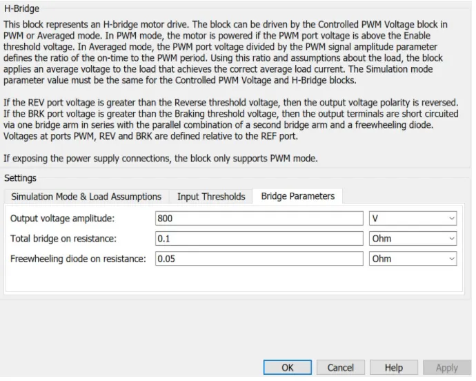
The H-Bridge block represents an H-bridge motor driver. The block has the following two Simulation mode options:
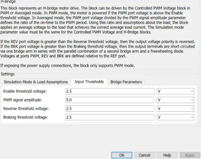
PWM — The H-Bridge block output is a controlled voltage that depends on the input signal at the PWM port. If the input signal has a value greater than the Enable threshold voltage parameter value, the H-Bridge block output is on and has a value equal to the value of the Output voltage amplitude parameter. If it has a value less than the Enable threshold voltage parameter value, the block maintains the load circuit using one of the following three Freewheeling mode options:
Via one semiconductor switch and one freewheeling diode
Via two freewheeling diodes
Via two semiconductor switches and one freewheeling diode
The first and third options are sometimes referred to as synchronous operation.
The signal at the REV port determines the polarity of the output. If the value of the signal at the REV port is less than the value of the Reverse threshold voltage parameter, the output has positive polarity; otherwise, it has negative polarity.
Averaged — This mode has two Load current characteristics options:
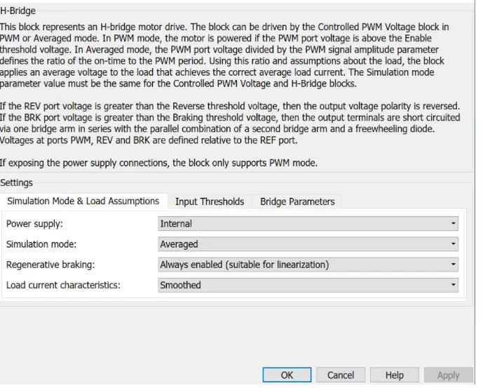
Smoothed
Unsmoothed or discontinuous
The Smoothed option assumes that the current is practically continuous due to load inductance. In this case, the H-Bridge block output is:
V
O
V
PWM
A
PWM
−I
OUT
R
ON
where:
VO is the value of the Output voltage amplitude parameter.
VPWM is the value of the voltage at the PWM port.
APWM is the value of the PWM signal amplitude parameter.
IOUT is the value of the output current.
RON is the Bridge on resistance parameter.
The current will be smooth if the PWM frequency is large enough. Synchronous operation where freewheeling is via a bridge arm back to the supply also helps smooth the current. For cases where the current is not smooth, or possibly discontinuous (that is, it goes to zero between PWM cycles), use the Unsmoothed or discontinuous option. For this option, you must also provide values for the Total load series resistance, Total load series inductance and PWM frequency. During simulation, the block uses these values to calculate a more accurate value for H-bridge output voltage that achieves the same average current as would be present if simulating in PWM mode.
Set the Simulation mode parameter to Averaged to speed up simulations when driving the H-Bridge block with a Controlled PWM Voltage block. You must also set the Simulation mode parameter of the Controlled PWM Voltage block to Averaged mode. This applies the average of the demanded PWM voltage to the motor. The accuracy of the Averaged mode simulation results relies on the validity of your assumption about the load current. If you specify that the current is Unsmoothed or discontinuous, then the accuracy also depends on the values you provide for load resistance and inductance being representative. This mode also makes some simplifying assumptions about the underlying equations for the case when current is discontinuous. For typical motor and bridge parameters, accuracy should be within a few percent. To verify Averaged mode accuracy, run the simulation using the PWM mode and compare the results to those obtained from using the Averaged mode.
Braking mode is invoked when the voltage presented at the BRK port is larger than the Braking threshold voltage. Regardless of whether in PWM or Averaged mode, when in braking mode the H-bridge is modeled by a series combination of two resistances R1 and R2 where:
R1 is the resistance of a single bridge arm, that is, half the value of the Total bridge on resistance parameter.
R2 is the resistance of a single bridge arm in parallel with a diode resistance, that is, R1 · Rd / ( R1 + Rd ), where Rd is the diode resistance.
H-bridge parameter:-
4) DC motor:-
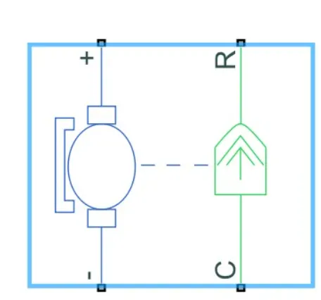
The DC Motor block represents the electrical and torque characteristics of a DC motor using the following equivalent circuit model:
You specify the equivalent circuit parameters for this model when you set the Model parameterization parameter to By equivalent circuit parameters. The resistor R corresponds to the resistance you specify in the Armature resistance parameter. The inductor L corresponds to the inductance you specify in the Armature inductance parameter. The permanent magnets in the motor induce the following back emf vb in the armature:
v
b
=k
v
ω
where kv is the Back-emf constant and ω is the angular velocity. The motor produces the following torque, which is proportional to the motor current i:
T
E
=k
t
i
where kt is the Torque constant. The DC Motor block assumes that there are no electromagnetic losses. This means that mechanical power is equal to the electrical power dissipated by the back emf in the armature. Equating these two terms gives:
T
E
ω=v
b
i
k
t
iω=k
v
ωi
k
v
=k
t
As a result, you specify either kv or kt in the block parameters.
The torque-speed characteristic for the DC Motor block is related to the parameters in the preceding figure. When you set the Model parameterization parameter to By stall torque & no-load speed or By rated power, rated speed & no-load speed, the block solves for the equivalent circuit parameters as follows:
For the steady-state torque-speed relationship, L has no effect.
Sum the voltages around the loop and rearrange for i:
i=
V−v
b
R
=
V−k
v
ω
R
Substitute this value of i into the equation for torque:
T
E
=
k
t
R
(V−k
v
ω)
When you set the Model parameterization parameter to By stall torque & no-load speed, the block uses the preceding equation to determine values for R and kt (and equivalently kv).
When you set the Model parameterization parameter to By rated power, rated speed & no-load speed, the block uses the rated speed and power to calculate the rated torque. The block uses the rated torque and no-load speed values in the preceding equation to determine values for R and kt.
The block models motor inertia J and damping λ for all values of the Model parameterization parameter. The resulting torque across the block is:
T=
k
t
R
(V−k
v
ω)−J
˙
ω
−λω
It is not always possible to measure rotor damping, and rotor damping is not always provided on a manufacturer datasheet. An alternative is to use the no-load current to infer a value for rotor damping.
For no-load, the electrically-generated mechanical torque must equal the rotor damping torque:
k
t
i
noload
=λω
noload
where inoload is the no-load current. If you select By no-load current for the Rotor damping parameterization parameter, then this equation is used in addition to the torque-speed equation to determine values for λ and the other equation coefficients.
The value for rotor damping, whether specified directly or in terms of no-load current, is taken into account when determining equivalent circuit parameters for Model parameterization options By stall torque and no-load speed and By rated power, rated speed and no-load speed.
When a positive current flows from the electrical + to - ports, a positive torque acts from the mechanical C to R ports.
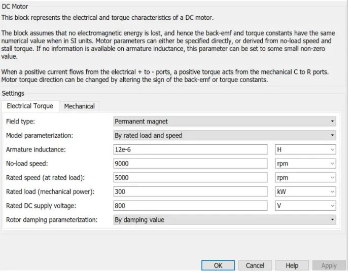
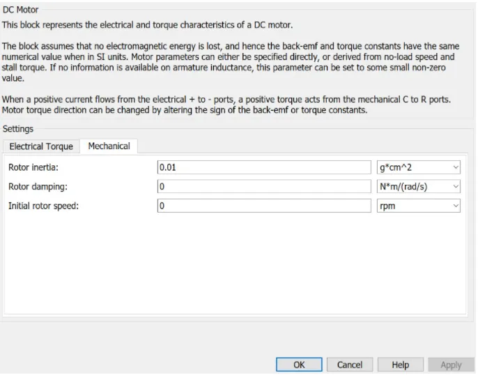
DC motor parameter:-
5) Battery source 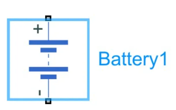 :-
:-
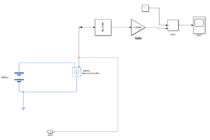
state of charge (SoC) is the level of charge of an electric battery relative to its capacity. The units of SoC are percentage points (0% = empty; 100% = full). An alternative form of the same measure is the depth of discharge (DoD), the inverse of SoC (100% = empty; 0% = full). SoC is normally used when discussing the current state of a battery in use, while DoD is most often seen when discussing the lifetime of the battery after repeated use.
In a battery electric vehicle (BEV), hybrid vehicle (HV), or plug-in hybrid electric vehicle (PHEV), SoC for the battery pack is the equivalent of a fuel gauge. It is important to mention that state of charge, presented as a gauge or percentual value at any vehicle dashboard, especially in plug-in hybrid vehicles, may not be representative for a real level of charge. In that particular case, some noticeable amount of energy stored in the electric battery is not shown at the dashboard, and it is reserved for hybrid-work operations. It permits a vehicle to accelerate with electric motor(s) mainly using battery energy, while engine serves as a generator is used to recharge the battery to the minimum level needed for such operation. Examples of such cars are Mitsubishi Outlander PHEV (all versions/years of production), where 0% of the state of charge presented to the driver is a real 20-22% of charge level (assuming zero level as the lowest level of charge permitted by car producer).
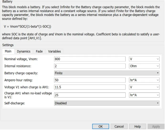
battery parameter:-
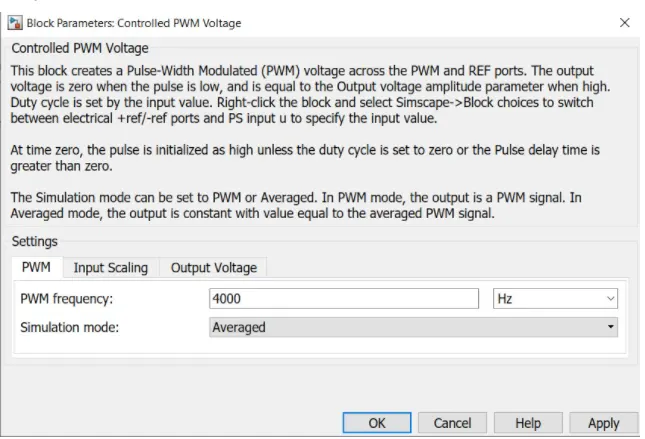
6) Controlled PWM voltage:-
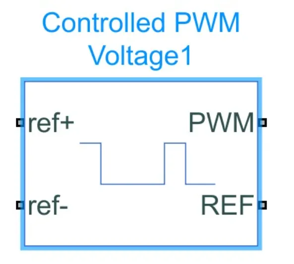
he Controlled PWM Voltage block represents a pulse-width modulated (PWM) voltage source. The block has two modeling variants, accessible by right-clicking the block in your block diagram and then selecting the appropriate option from the context menu, under Simscape > Block choices:
Electrical input ports — The block calculates the duty cycle based on the reference voltage across its ref+ and ref- ports. This modeling variant is the default.
PS input — Specify the duty cycle value directly by using an input physical signal port.
For the Electrical input ports variant of the block, the demanded duty cycle is
100∗
V
ref
−V
min
V
max
−V
min
percent
where:
Vref is reference voltage across the ref+ and ref- ports.
Vmin is the minimum reference voltage.
Vmax is the maximum reference voltage.
The value of the Output voltage amplitude parameter determines amplitude of the output voltage.
At time zero, the pulse is initialized as high, unless the Pulse delay time parameter is greater than zero, or the demanded duty cycle is zero.
You can use parameters Pulse delay time and Pulse width offset to add a small turn-on delay and a small turn-off advance. This can be useful when fine-tuning switching times so as to minimize switching losses.
In PWM mode, the block has two options for the type of switching event when moving between output high and output low states:
Asynchronous – Best for variable-step solvers — Asynchronous events are better suited to variable step solvers, because they require fewer simulation steps for the same level of accuracy. In asynchronous mode the PWM switching events generate zero crossings, and therefore switching times are always determined accurately, regardless of the simulation maximum step size.
Discrete—time – Best for fixed-step solvers — Discrete-time events are better suited to fixed-step operation, because then the switching events are always synchronized with the simulation step. Using an asynchronous implementation with fixed-step solvers may sometimes result in events being up to one simulation step late. For more information, see Simulating with Fixed Time Step — Local and Global Fixed-Step Solvers (Simscape).
If you use a fixed-step or local solver and the discrete-time switching event type, the following restrictions apply to the Sample time parameter value:
The sample time must be a multiple of the simulation step size.
The sample time must be small compared to the PWM period, to ensure sufficient resolution.
PWM parameters:-
7)Vehicle:-
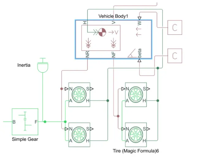
the components are
simple gear :- for enganging right gear at the duration
tyre:-4 tyres and the operationals wheels are rear
angle:- depend on road condition and slope on which car is running
velocity:-the speed of car
NF:-front wheel connection
NR:-rear wheel connection
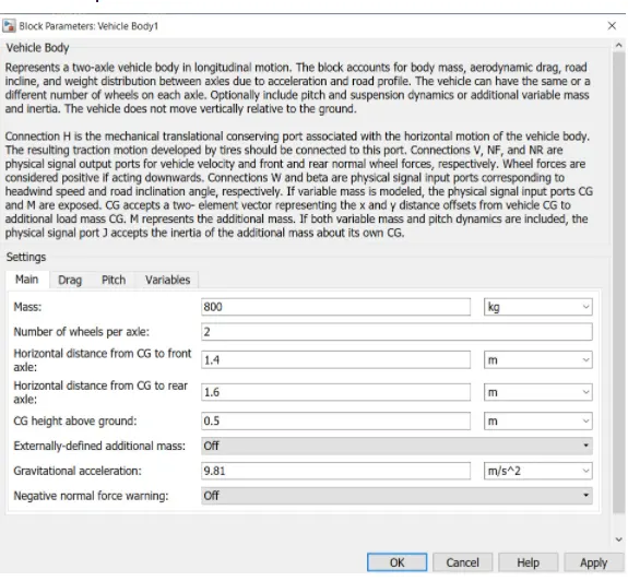
vehicle parameters:-
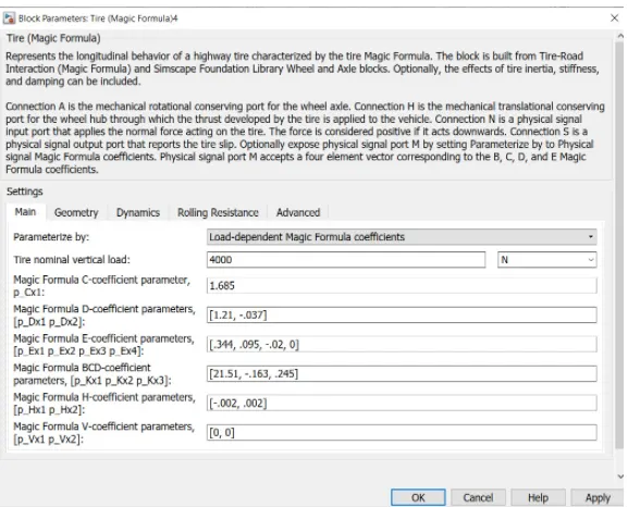
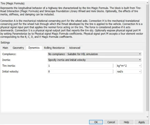
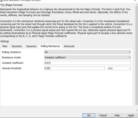
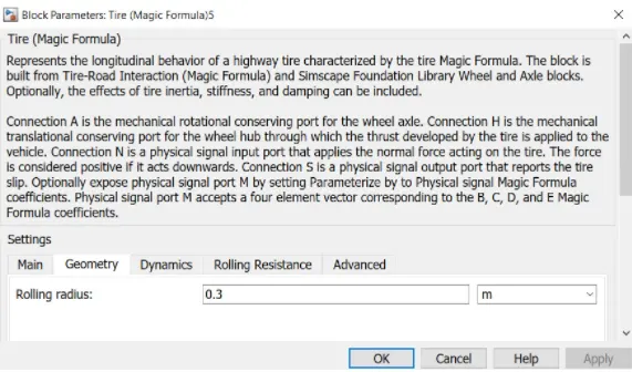
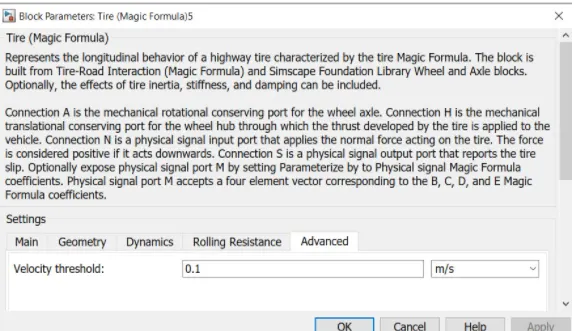
tyre parameter:-
results:-
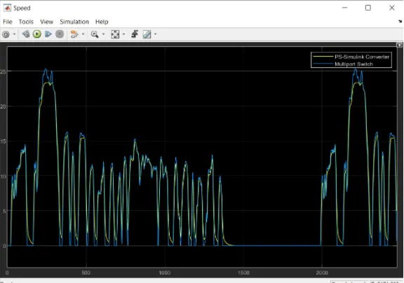
velocity feedback and drive cycle source
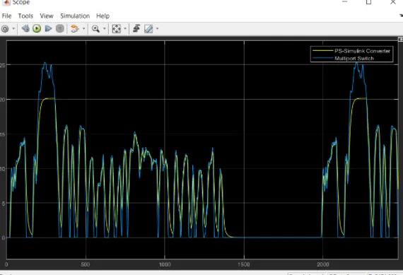
with increase motoring rate velocity feedback and drive cycle
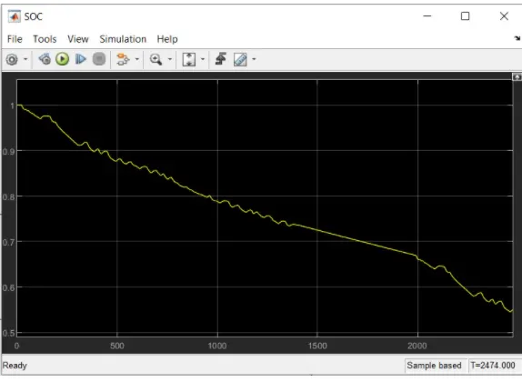
at the start the battery is 100% as accleration is applied is reduce to 50% after that it start increases due to regenrative braking and deleraction.
conclusion:-
the vehicle as achieved max speed of 20m/s but did not achive 25m/s max speed of drive cycle but by increasing the motor power and volatage we have achieved the max speed of 25m/s.