Roll-bar Selection and Understeer Budget for a Lightweight Sports Vehicle
Problem Statement:
Select anti-roll bar diameters and K&C parameters to achieve maximum possible understeer gradient for lightweight sporty vehicle.
Targets:
| Target | Units | Values |
| Roll gradient | deg/g | 3.50 - 3.80 |
| Understeer gradient @tires | deg/g | Max possible |
Target Cascade:
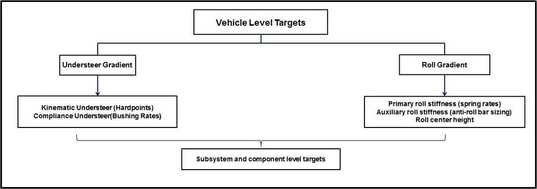
Constraints:
| Parameter | Max | Min |
| Auxillary roll stiffness front (%) | 60 | 25 |
| Auxillary roll stiffness rear (%) | 20 | 0 |
| Roll steer front (%) | 6.50 | 3 |
| Roll steer rear (%) | -4 | -8 |
| Roll camber front (%) | 90 | 80 |
| Roll camber rear (%) | 65 | 50 |
| Lateral force compliance steer front (deg/kN) | 0.05 | 0.008 |
| Lateral force compliance steer rear (deg/kN) | 0.04 | 0.015 |
| Lateral force compliance camber front (deg/kN) | 0.3 | 0.1 |
| Lateral force compliance camber rear (deg/kN) | 0.4 | 0.15 |
| Aligning torque compliance steer front (deg/100 Nm) | 0.4 | 0.2 |
| Aligning torque compliance steer rear (deg/100 Nm) | 0.1 | 0.06 |
Deliverables:
- Roll bar outer diameters (front and rear) (mm).
- Primary and secondary roll stiffness at the wheel center (ft-lb/deg)
- Auxiliary roll stiffness (front and rear) (%).
- Tire stiffness plots (stiffness vs load).
- Understeer budget sheet.
- Contribution bar chart.
Input Data:
Vehicle Weights and Dimension:
| Parameter | Unit | Value |
| Total Weight | lb | 2750 |
| Weight Distribution | %front | 60 |
| Front axle unsprung mass | lb | 187 |
| Rear axle unsprung mass | lb | 121 |
| Wheelbase | in | 98.42 |
| Cg height | in | 21.62 |
| Trackwidth | in | 58 |
| Front Roll Center height | in | 0.497 |
| Rear Roll Center height | in | 0.896 |
Springs:
| Parameter - Front | Unit | Value |
| Motion ratio | in/in | 0.95 |
| Spring rate | lb/in | 250 |
| Parameter - Rear | Unit | Value |
| Motion ratio | in/in | 0.8 |
| Spring rate | lb/in | 300 |
Anti-Roll Bars:
| Parameter - Front | Unit | Value |
| Motion ratio | in/in | 0.64 |
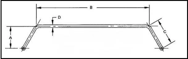
| Virtual torque arm (A) | in | 8.90 |
| Center length (B) | in | 32.00 |
| Physical torque arm (C) | in | 10.70 |
| Parameter - Rear | Unit | Value |
| Motion ratio | in/in | 0.75 |
| Virtual torque arm (A) | in | 8.51 |
| Center length (B) | in | 32.28 |
| Physical torque arm (C) | in | 8.59 |
Tires: Front and Rear:
| Parameter | Unit | Value |
| Loaded radius | in | 12.27 |
| Vertical stiffness | lb/in | 1313 |
| Normal Load | Cornering Stiffness | Camber Stiffness | Aligning Stiffness |
| lb | lb/deg | lb/deg | ft-lb/deg |
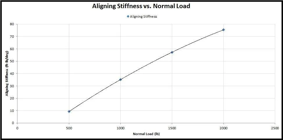
| 500 | 167.23 | 8.37 | 9.27 |
| 1000 | 262.17 | 17.76 | 35.12 |
| 1500 | 301.75 | 25.30 | 57.26 |
| 2000 | 269.86 | 29.90 | 75.36 |
| Tire Response | Unit | Front | Rear |
| Slip angle | deg/g | 3.88 | 3.10 |
| Camber | deg/g | 4.55 | 2.26 |
| Lateral force | N/g | 3753 | 2375 |
| Aligning torque | Nm/g | 139.8 | 50.8 |
Additional Information and Assumptions:
- Roll bar diameters are available only in increments of 0.25.
- The roll bar is a solid bar.
- 5% higher load transfer in the front.
- A 5% deviation in all targets is allowed.
Work Flow:
- Derive the longitudinal Cg location, rolling moment arm, and sprung mass from the given data.
- Calculate roll moment and the total roll stiffness based on the roll gradient target.
- Determine total load transfer, proportions of the total load transfer front to rear and its components
- Determine the roll stiffness contributon of tires and springs to evaluate the arb stiffness at each axle.
- Compute tire stiffness properties from the given tire data.
- Determine the weight, kinematic and compliance parameters contribution to the total understeer budget.
STAGE 1:
ROLL ANALYSIS AND ANTI-ROLL BAR SELECTION:
The selection of the anti-roll bar depends on the target roll gradient which comprehensively describes the roll characteristics of the vehicle.
Step 1: Using the vehicle weight and dimensions parameters from the input data following sprung mass data is derived:
| Parameter | Unit | Front | Rear |
| Total axle mass | lb | 1650 | 1100 |
| Sprung mass | lb | 1463 | 979 |
| Sprung mass/corner | lb | 731.5 | 489.5 |
Total sprung mass = 2442 lb
Longitudinal location of Cg:
From the front axle:
`a =` (Rear weight distribution %) * Wheelbase
`a = 39.368` in
From the rear axle:
`b =` (Front weight distribution %) * Wheelbase
`b = 59.052` in
Roll moment arm:
`h_(arm) = h_s − ((Z_f*b−Z_r*a)/l)`
where,
`h_s −` Sprung mass Cg height (in)
`Z_f −` Front roll center height (in)
`Z_r −` Rear roll center height (in)
`a −` Distance of Cg from front axle (in)
`b −` Distance of Cg from rear axle (in)
`l −` Wheelbase (in)
`h_(arm) = 20.9634` in
Now, from the target roll gradient and the derived roll moment arm the required roll moment is calculated.
Wheel rate:
Front:
`K_(wf) = K_(fs)*(MR_(f)^2)`
where,
`K_(fs) -` Spring rate (lb/in)
`MR_(f) -` Motion ratio (in/in)
`K_(wf) = 225.625` lb/in
Rear:
`K_(wr) = K_(rs)*(MR_(r)^2)`
where,
`K_(rs) -` Spring rate (lb/in)
`MR_(r) -` Motion ratio (in/in)
`K_(wf) = 192` lb/in
Step 2: Evaluation of roll moment and total roll stiffness:
Roll moment:
`M_ϕ = (W_s*h_(arm))/12*(1+ϕ_(r)*(π/180))`
where,
`M_ϕ −`Roll moment (ft-lb/g)
`W_s -` Total sprung mass (lb)
`h_(arm) −` Roll moment arm (in)
`ϕ_(r) -` Target roll gradient (deg/g)
`M_(ϕ) = 4548.987177` ft-lb/deg
Target total roll stiffness is derived from the obtained value of roll moment and the target roll gradient
Total roll stiffness:
`K_(ϕ) = M_(ϕ)/ϕ_(r)`
where,
`M_(ϕ) -` Roll moment (ft-lb/g)
`ϕ_(r) -` Target roll gradient (deg/g)
`K_(ϕ) = 1197.101889` ft-lb/deg
Step 3: Evaluation of total lateral load transfer and its components:
The total lateral load transfer is calculated by distributing 5% of the total towards the front for understeer effect.
Total lateral load transfer:
`LLT_(t) = (W_(t)*h)/t`
where,
`W_t -` Total weight (lb)
`h -` Cg height (in)
`t -` Trackwidth (in)
`LLT_t = 1025.086207` lb/g
Front lateral load transfer:
`LLT_f = LLT_t*(FrontWeightDistribution % + 5 %)*0.01`
`LLT_f = 666.3060345` lb/g
Rear lateral load transfer:
`LLT_r = 358.7801724` lb/g
In order to compute the axle stiffness due to lateral load transfer, it is essential to determine the individual components of the total load transfer due to unsprung mass and direct lateral force (kinematic load transfer component) respectively.
For front axle:
Load transfer due to unsprung mass:
`LLT_(fu) = (W_(fu)*R_(fl))/t`
where,
`W_(fu) -` Front unsprung mass (lb)
`R_(fl) -` Front loaded radius (in)
`t -`Trackwidth (in)
`LLT_(fu) = 39.56017241` lb/g
Load transfer due to direct lateral force:
`LLT_(fs) = (W_(fs)*Z_(f))/t`
where,
`W_(fs) -` Front sprung mass (lb)
`Z_f -` Front loaded radius (in)
`t -` Trackwidth (in)
`LLT_(fs) = 12.53639655` lb/g
For rear axle:
Load transfer due to unsprung mass:
`LLT_(ru) = 25.59775862` lb/g
Load transfer due to direct lateral force:
`LLT_(rs) = 15.12386207` lb/g
Step 4: Evaluation of total axle roll stiffness:
Front axle:
`K_(ϕft) = ((LLT_f - LLT_(fu) - LLT_(fs))*t)/(ϕ_r*12)`
where,
`LLT_f -` Total lateral load transfer (lb/g)
`LLT_(fu) -` Load transfer due to unsprung mass (lb/g)
`LLT_(fs) -` Load transfer due to direct lateral force (lb/g)
`K_(ϕft) = 781.2313377` ft-lb/deg
Rear axle:
`K_(ϕrt) = 415.8705508` ft-lb/deg
Step 5: Evaluation of tire and spring contribution to roll stiffness:
In order to determine the arb contribution to the total roll stiffness it is essential to compute the tire and the spring contribution respectively.
For Front axle:
Tire contribution to roll stiffness:
`K_(ϕftire) = (((K_(ft)/0.0833333)*(t*0.0833333)^2)/2)*(π/180)`
where,
`K_(ft) -` Tire vertical stiffness (lb/in)
`t -` Trackwidth (in)
`K_(ϕftire) = 3212.082308` ft-lb/deg
Spring contribution to roll stiffness:
`K_(ϕfw) = (((K_(wf)/0.0833333)*(t*0.0833333)^2)/2)*(π/180)`
where,
`K_(wf) -` Wheel rate (lb/in)
`t -` Trackwidth (in)
`K_(ϕfw) = 551.9619732` ft-lb/deg
For Rear axle:
Tire contribution to roll stiffness:
`K_(ϕrtire) = 3212.082308` ft-lb/deg
Spring contribution to roll stiffness:
`K_(ϕrw) = 469.7028204` ft-lb/deg
Step 6: Evaluation of auxillary roll stiffness:
Further the tire effect needs to be isolated to determine the arb contribution to roll stiffness.
For front axle:
Roll stiffness at wheel center level:
`K_(ϕfwc) = (K_(ϕftire)*K_(ϕft))/|K_(ϕftire) - K_(ϕft)|`
where,
`K_(ϕftire) -`- Tire contribution to roll stiffness (ft-lb/deg)
`K_(ϕft) -` Axle roll stiffness (ft-lb/deg)
`K_(ϕfwc) = 1032.304896` ft-lb/deg
ARB contribution to roll stiffness:
`K_(ϕfarb) = (K_(ϕfwc) - K_(ϕfw))*12`
where,
`K_(ϕfwc) -` Roll stiffness at wheel center level (ft-lb/deg)
`K_(ϕfw) -` Spring contribution to roll stiffness (ft-lb/deg)
`K_(ϕfarb) = 5764.115074` in-lb/deg
For rear axle:
Roll stiffness at wheel center level:
`K_(ϕrwc) = 477.7214871` ft-lb/deg
ARB contribution to roll stiffness:
`K_(ϕrarb) = 96.22399964` in-lb/deg
Step 7: Auxillary roll stiffness constraint check:
| Constraints | Unit | Value |
| Max. allowed front auxillary roll stiffness | % | 60.00 |
| Max. allowed rear auxillary roll stiffness | % | 30.00 |
| Obtained | Unit | Value |
| Front auxillary roll stiffness | % | 61.45 |
| Rear auxillary roll stiffness | % | 1.92 |
The auxillary roll stiffness is higher than the constraint value. To achieve the value within the specified range it is essential to increase the primary roll stiffness contribution for which the front ride frequency needs to be iterated. Since the two variable parameters, (tire stiffness and spring rate) on which the ride frequency is dependent are fixed the contribution of 61.45% of front auxillary roll stiffness is acceptable since it lies within the range of 5% deviation acceptable for the targets.
Step 8: Roll rate due to Anti-roll bar:
For front axle:
`K_(farb) = (K_(ϕfarb)/(MR_(farb)^2*t^2))*(180/π)`
where,
`K_(ϕfarb) -` ARB contribution to roll stiffness (in-lb/deg)
`MR_(farb) -` ARB motion ratio (in/in)
`t -` Trackwidth (in)
`K_(farb) = 239.6841633` lb/in
For rear axle:
`K_(rarb) = 2.913583864` lb/in
Anti-roll bar diameter is calculated considering the bar to be solid and the material to be steel.
Step 9: Diamter of anti-roll bar:
For front axle:
`OD = (((K_(farb)*((0.4422*A^2*B)+(0.2264*C^3)))/500000)^0.25)*25.4`
where,
`K_(farb) -` Roll rate due to Anti-roll bar (lb/in)
`A -`Virtual torque arm of arb (in)
`B -` Center length (in)
`C -` Physical torque arm (in)
`OD = 22.98230594 ~ 23.00` mm
For rear axle:
`OD = 7.309951323 ~ 7.50` mm
The obtained anti-roll bar dimensions are:
| Parameter | Unit | Front | Rear |
| ARB Diameter | mm | 23.00 | 7.50 |
Stage 2:
Computing Tire Stiffness properties:
The tire stiffness parameters are essential to determine the
1. Cornering Stiffness:
The relationship between the cornering force and the slip angle is of fundamental importance to the directional control and stability of road vehicles. The cornering force is proportional to the slip angle and its relationship is given as:
`F_y prop alpha`
`:. F_y = C_(alpha)*alpha`
where,
`alpha -` Slip angle
`C_(alpha) -` Cornering stiffness
Cornering stiffness signifies the rate of change of the (lateral force) cornering force with respect to slip angle.
A number of factors affect the cornering behavior of the tires, of which the normal load and slip angle of the tire strongly influences the cornering characteristics.
The plot obtained from the given data shows the influence of normal load on the cornering stiffness.
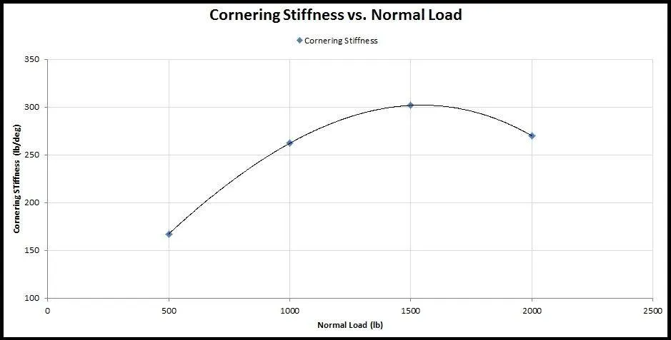
Therefore it is evident that for a given slip angle, the cornering stiffness generally increases with an increase of the normal load. However, the relationship between the cornering stiffness and the normal load is nonlinear. Thus, the transfer of load from the inside to the outside tire during a turning maneuver will reduce the total cornering force that an axle can develop.
2. Camber Stiffness
Camber causes a lateral force developed on the contact patch. This lateral force is usually referred to as camber thrust. The camber thrust is proportional to the camber angle and its relationship is given as:
`F_(yc) prop gamma`
`:. F_(yc) = C_(gamma)*gamma`
where,
`gamma -` Camber angle
`C_(gamma) -` Camber stiffness
Camber stiffness signifies the rate of change of the (lateral force) camber thrust with respect to camber angle.
Similar to the cornering stiffness, the normal load and inflation pressure have an influence on the camber stiffness.
The plot obtained from the given data shows the influence of normal load on the camber stiffness.
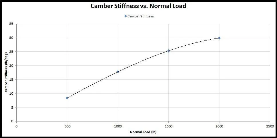
Therefore it is evident that the camber stiffness varies almost linearly with the normal load.
3. Aligning Stiffness
The lateral force developed as a consequence of slip angle does not act at the center of the contact patch but instead at some offset behind the contact patch due to uneven stress distribution. This offset is termed as pneumatic trail and the resulting moment is the aligning moment which tries to align the tire in the original direction of travel, thus having a stabilizing influence on the vehicle.
The plot obtained from the given data shows the influence of normal load on the cornering stiffness.
Stage 3:
Understeer Budget:
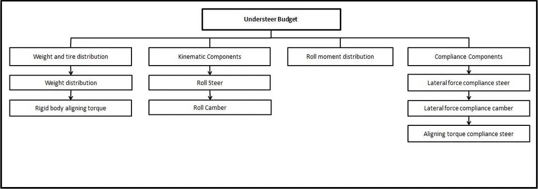
1. Weight and Tire distribution:
a. Weight distribution:
The understeer budget is computed using the 2-DOF bicycle model. The model takes into account 2-DOF, yaw velocity and the lateral velocity and is used to evalute the tire and weight contribution towards the total understeer budget.
Model assumptions:
- There is no lateral load transfer. (single track)
- There is no longitudinal load transfer.
- There is no roll and pitch motions.
- Linear range tires.
- Constant forward velocity.
- Chassis and suspension compliance effects are not taken into consideration.
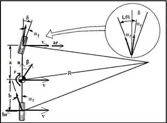
The lateral forces generated at the front and the rear axle are:
`F_(yf) = W_(f)*(u^2/(Rg))`
`F_(yr) = W_(r)*(u^2/(Rg))`
where,
`W_(f) -` Weight on front axle
`W_(r) -` Weight on rear axle
`u -` Longitudinal speed
`R -` Turn radius
But,
`F_(yf) = C_(alphaft)*alpha_(f)`
`F_(yr) = C_(alphart)*alpha_(r)`
where,
`C_(alphaft) -` Total cornering stiffness of the axle
`C_(alphart) -` Total cornering stiffness of the axle
`alpha_(f) -` Front slip angle
`alpha_(r) -` Rear slip angle
Therefore from the above two equations the front and rear slip angle are given as:
`alpha_(f) = (W_(f)*u^2)/(C_(alphaf)Rg)`
`alpha_(r) = (W_(r)*u^2)/(C_(alphar)Rg)`
The steering angle is given as
`delta = 57.3*(L/R) + alpha_(f) - alpha_(r)`
`delta = 57.3*(L/R) + [(W_(f)/C_(alphaf)) - (W_(r)/C_(alphar))]*(u^2/(Rg))`
`delta = 57.3*(L/R) + K*a_(y)`
where,
`L -` Wheelbase
`R -` Turn radius
`K -` Understeer gradient
`a_(y) -` Lateral acceleration
`:. K = [(W_(f)/C_(alphaft)) - (W_(r)/C_(alphart))]`
Therefore the 'weight distribution' contribution to the total understeer budget is:
`W_(d) = [(W_(f)/(2*C_(alphaf))) - (W_(r)/(2*C_(alphar)))]`
where,
`W_(f) -` Weight on front axle
`W_(r) -` Weight on rear axle
`C_(alphaf) -` Front tire cornering stiffness
`C_(alphaf) -` Rear tire cornering stiffness
b. Rigid body aligning torque:
The aligning torque experienced by the tires on a vehicle always resist the attempted turn and hence its a source of understeer. This always produces an understeer effect on the front axle and the rear axle. Therefore a negative sign is introduced in the equation for rear axle.
The Rigid body aligning torque contribution to the total understeer budget is:
`RB_(AT) = ((W_(f)/(2*C_(alphaf)))*(p_r/b))-(-(W_(r)/(2*C_(alphar)))*(p_f/a))`
where,
`W_(f) -` Weight on front axle
`W_(r) -` Weight on rear axle
`C_(alphaf) -` Front tire cornering stiffness
`C_(alphaf) -` Rear tire cornering stiffness
`p_f -` Front tire pnuematic trail
`p_r -` Front tire pnuematic trail
`a -` Distance of Cg from front axle
`b -` Distance of Cg from rear axle
2. Kinematic Components:
a. Roll Steer:
The roll steer is defined as undesirable and uncontrollable changes in the steering angle of the steered wheels during the rolling action of the vehicle body due to cornering maneuver or asymmetric bumps. This effect is the result of the geometry setup of the suspension links and the tierod. If the tierod is not aimed at the instant center or if it is not the correct length for its location, then the steering and suspension would move about different centers and this would result in a steer that will occur with suspension travel called ride steer or bump steer. The roll steer affects handling and dynamic stability of the vehicle due to variation of the angles of the wheel and the suspension links.
The Roll steer contribution to the total understeer budget is:
`RS = (RSC_(f) - RSC_(r))*phi`
where,
`RSC_(f) -` Front roll steer coefficient
`RSC_(r) -` Rear roll steer coefficient
`phi -` Roll gradient
b. Roll Camber:
Roll camber is the term that describes the change of camber with respect to body roll. The amount of camber variation depends on the geometry setup.
The Roll camber contribution to the total understeer budget is:
`RC = (RC_(f)*(C_(gammaf)/C_(alphaf)) - RC_(r)*(C_(gammar)/C_(alphar)))*phi`
where,
`RC_(f) -` Front roll camber coefficient
`RC_(r) -` Rear roll camber coefficient
`C_(gammaf) -` Front camber stiffness
`C_(gammar) -` Rear camber stiffness
`C_(alphaf) -` Front tire cornering stiffness
`C_(alphaf) -` Rear tire cornering stiffness
`phi -` Roll gradient
3. Compliance Components:
a. Lateral force compliance steer:
This component is the effect of the relative stiffness of the suspension steering systems and the location of the steering rack. The stiffness includes includes contribution from various links with their leverages being taken into consideration.
For a rear mounted rack if the steering system is more compliant than the suspension system, the lateral force causes the wheel to deflect away from the turn, hence producing an understeer effect.
The Lateral force compliance steer contribution to the total understeer budget is:
`LF_(cs) = LFCS_(f)*F_(yf) - LFCS_(r)*F_(yr)`
where,
`LFCS_(f) -` Front lateral force compliance steer coefficient
`LFCS_(r) -` Rear lateral force compliance steer coefficient
`F_(yf) -` Front lateral force
`F_(yr) -` Rear lateral force
b. Lateral force compliance camber:
Since the lateral force acts at the ground, resulting in leaning the top of the tire to tilt away from the turn center. This in turn causes the tires to lose the cornering capability.
The Lateral force compliance camber contribution to the total understeer budget is:
`LF_(Cgamma) = LFC_(f)*F_(yf)*C_(gammaf)/C_(alphaf) - LFC_(r)*F_(yr)*C_(gammar)/C_(alphar)`
where,
`LFC_(f) -` Front lateral force compliance camber coefficient
`LFC_(r) -` Rear lateral force compliance camber coefficient
`F_(yf) -` Front lateral force
`F_(yr) -` Rear lateral force
`C_(gammaf) -` Front camber stiffness
`C_(gammar) -` Rear camber stiffness
`C_(alphaf) -` Front tire cornering stiffness
`C_(alphaf) -` Rear tire cornering stiffness
c. Aligning torque compliance steer:
Aligning torque always tends to straighten the wheel which results into generating an understeer effect at the front and an oversteer effect at the rear axle.
The Aligning torque compliance steer contribution to the total understeer budget is:
`AT_(CS) = ATCSC_(f)*AT_(f) - ATCSC_(r)*AT_(r)`
where,
`ATCSC_(f) -` Front aligning torque compliance steer coefficient
`ATCSC_(r) -` Rear aligning torque compliance steer coefficient
`AT_(f) -` Front aligning torque
`AT_(r) -` Rear aligning torque
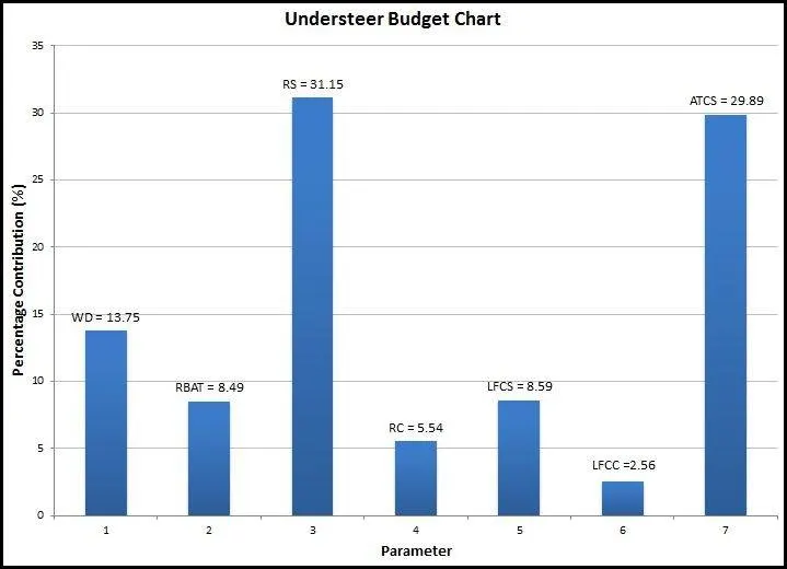
Understeer budget chart:
Plot Inference:
- The roll steer component contributes maximum to the understeer budget.This component can be tuned by iterating the suspension geometry for different configurations of hardpoints.
- The next highest contributor is the Aligning torque compliance steer. This parameter can be tuned for a desired value by iterating the compliance of the suspension and the steering system.
- Third highest contributor is the wieght distribution which is difficult to tune.
- Contribution of Rigid body aligning torque, Roll camber, Lateral force compliance steer are in the intermediate range.
Conclusion:
Selected anti-roll bar diameters and K&C parameters to achieve the maximum possible target understeer gradient of 1.768 deg/g.
Calculations: