Determining Baseline Suspension Setup for 4WD Sedan
Problem Statement:
Select springs and anti-roll bars, and set up swing arm geometry for a 4WD sedan with a McPherson strut suspension in the front and a multilink setup in the rear, to meet targets for ride frequency, roll gradient and pitch gradient, while staying within specified constraints.
Targets:
| Target | Unit | Value |
| Front ride frequency | Hz | 1.35 |
| Roll gradient | deg/g | 3.80 |
| Acceleration pitch gradient | deg/g | 2.00 |
| Braking pitch gradient | deg/g | 1.00 |
| Constraints | Unit | Value |
| Max. allowed front auxillary roll stiffness | % | 60.00 |
| Max. allowed rear auxillary roll stiffness | % | 30.00 |
Deliverables:
- Spring rates (front and rear)
- Roll bar diameters (front and rear)
- Rear ride frequency and flat ride plot (at 65 mph)
- Anti characteristics (front and rear - in terms of percentages and instant center locations)
Input Data:
Vehicle Weights and Dimension:
| Parameter | Unit | Value |
| Total Weight | lb | 3500 |
| Weight Distribution | %front | 55 |
| Front axle unsprung mass | lb | 200 |
| Rear axle unsprung mass | lb | 240 |
| Wheelbase | in | 98 |
| Cg height | in | 17 |
| Trackwidth | in | 58 |
| Front Roll Center height | in | 0.497 |
| Rear Roll Center height | in | 0.896 |
| Speed | mph | 65 |
Drive/Brake Proportions:
| Parameter | Unit | Value |
| Drive ratio - Front | - | 0.7 |
| Brake ratio - front | - | 0.6 |
Tires:
| Parameter - Front | Unit | Value |
| Loaded radius | in | 12.27 |
| Vertical stiffness | lb/in | 1567 |
| Parameter - Rear | Unit | Value |
| Loaded radius | in | 12.27 |
| Vertical stiffness | lb/in | 1764 |
Springs:
| Parameter - Front | Unit | Value |
| Motion ratio | in/in | 0.95 |
| Parameter - Rear | Unit | Value |
| Motion ratio | in/in | 0.8 |
Anti-Roll Bars:
| Parameter - Front | Unit | Value |
| Motion ratio | in/in | 0.64 |
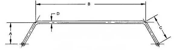
| Virtual torque arm (A) | in | 8.90 |
| Center length (B) | in | 32.00 |
| Physical torque arm (C) | in | 10.70 |
| Parameter - Rear | Unit | Value |
| Motion ratio | in/in | 0.75 |
| Virtual torque arm (A) | in | 8.51 |
| Center length (B) | in | 32.28 |
| Physical torque arm (C) | in | 8.59 |
Additional Information and Assumptions:
- The spring rates to be reported in lb/in, roll bar diameter in mm, ride frequency in Hz and swing arm height/length in inches.
- Spring rates and roll bar diameters are available only in increments of 0.25.
- The roll bar is a solid bar.
- We want a 5% higher load transfer in the front to get understeer.
- A 5% deviation in all targets is allowed.
- The percentages of anti characteristics cannot be negative or greater than 100.
- For swing arm horizontal distance, 70 to 120 inches is a reasonable starting point. From there on, optimize for pitch gradients.
Work Flow:
1. Ride frequency:
- Front ride frequency target is set.
- Calculate the time lag due to wheelbase and speed to evaluate a baseline rear ride frequency.
- Select springs based on this and check that the springs satisfy the other targets.
- Plot the bump profile to check the phase lag.
2. Roll gradient:
- Derive the longitudinal Cg location, rolling moment arm, and sprung mass from the given data.
- Calculate roll moment and the total roll stiffness based on the roll gradient target.
- Determine total load transfer, proportions of the total load transfer front to rear and its components
- Determine the roll stiffness contributon of tires and springs to evaluate the arb stiffness at each axle.
- Fix the spring rates obtained from the ride frequency split and check the constraint of auxillary roll stiffness.
3. Pitch gradient:
- Calculate load transfer, suspension deflection and pitch gradient using the baseline springs.
- Set up anti characteristics using the swing arm geometry to reach the target pitch gradient.
Target Cascade:
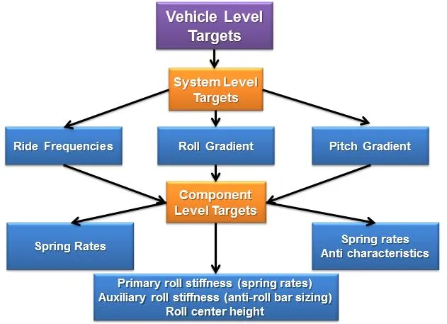
STAGE 1:
RIDE ANALYSIS AND SPRING SELECTION:
Ride frequency is the undamped natural frequency of the body in ride. As the ride frequency goes on increasing, the body has a stiffer response to an disturbance it encounters. Lower frequencies produce a softer suspension with more mechanical grip, and decent level of passenger comfort and are employed in passenger vehicles. Higher frequencies however create less suspension travel resulting in high degree of passenger discomfort. Therefore, the high frequency ride setups are utilized in race cars allowing lower ride heights, and in turn, low center of gravity.
Based on application following are the ballpark values of the ride frequencies to be considered:
| Vehicle Category | Unit | Value |
| Passenger cars | Hz | 0.5 - 1.5 |
| Moderate downforce formula cars | Hz | 1.5 - 2.0 |
| High downforce race cars | Hz | 3.0 - 5.0 + |
Target front ride frequency: 1.35 Hz (Passenger cars)
Rear Ride Frequency:
The following plot shows the effect of unequal ride frequencies front and rear as the vehicle encounters a disturbance (front frequency higher than the rear).
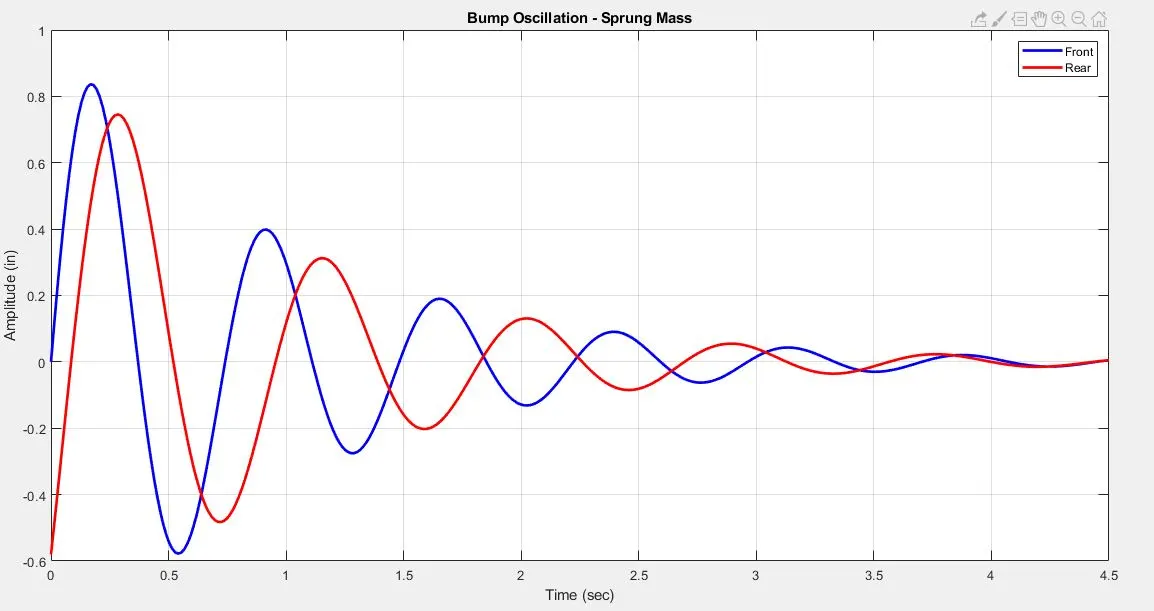
It can be inferred from the plot that the out of phase motion between front and rear vertical motion, caused by the time delay, is accentuated by the frequency difference. Hence to reduce the pitch induced by hitting a disturbance, the rear needs to have a higher frequency to catch up with the front. Thus the induced body pitch is minimized.
For a given wheelbase and speed of a passenger car a common frequency split is 10 – 20% front to rear.
Step 1: Time delay for the given wheelbase and speed and evaluation of rear ride frequency:
The time delay for the rear wheels to encounter a bump for the given wheelbase and speed is:
`t_d = l/(v⋅17.6)`
`t_d = 0.085664336` secs
where,
`l −` Wheelbase (in)
`v −`Vehicle speed (mph)
Rear ride frequency for the obtained time delay is:
`f_(rs) = 1/((1/f_(fs)) − (t_(d))`
`f_(rs) = 1.53` Hz
where,
`f_(fs) -` Front ride frequency (Hz)
`t_d −`Time delay (sec)
Step 2: Check for the modified bump oscillation profile:
The front and rear amplitudes for the generation of the bump oscillation profiles are:
Amplitude for front axle:
`A_f=e^(−t)*sin(2*π*f_(fs)*t)`
where,
`f_(fs) -` Ride frequency (Hz)
`t −` Time at a particular instant (sec)
Amplitude for rear axle:
`A_r = e^(−t)*sin(2*π⋅f_(rs)*(t−t_(d)))`
where,
`f_(rs) -`Ride frequency (Hz)
`t_d -` Time delay (sec)
`t −` Time at a particular instant (sec)
Therefore for the target front ride frequency of 1.35 Hz the evaluated rear ride frequency is 1.53 Hz. This results in a significant phase reduction for the initial high amplitude oscillation cycles thereby reducing the effective body pitch.
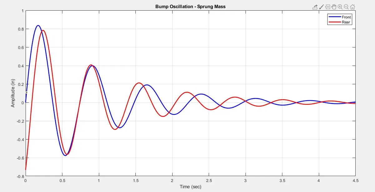
Therefore,
| Parameter | Unit | Value |
| Front ride frequency | Hz | 1.35 |
| Rear ride frequency | Hz | 1.53 |
The front to rear frequency split is 13.33%
Matlab script link:
https://drive.google.com/file/d/19Kc67BiuXCUAU26SlAPrx4TMuyF5F7bX/view?usp=sharing
Step 3: Evaluation of spring rates for the obtained frequency split:
For front:
Ride Rate:
`K_(rf) = (4*π^2*f_(fs)^2*m_(fs))/386.4`
where,
`f_(fs) −` Ride frequency (Hz)
`m_(fs) −` Sprung mass/corner (lb)
`K_(rf) = 160.7307846` lb/in
Wheel Rate:
`K_(wf) = (K_(tf)*K_(rf))/(K_(tf)−K_(rf))`
where,
`K_(tf) −` Tire stiffness (lb/in)
`K_(rf) −` Ride rate (lb/in)
`K_(wf) = 179.1016519` lb/in
Spring Rate:
`K_(fs) = K_(wf)/(MR_(f))^2`
where,
`K_(wf) −` Wheel rate (lb/in)
`MR_f −`Spring motion ratio
`K_(fs) = 198.4505838` lb/in
Therefore the front spring rate for the target front ride frequency of 1.35 Hz is 198.4505838 lb/in
For rear:
Ride Rate:
`K_(rr) = 159.7741646` lb/in
Wheel Rate:
`K_(wr) = 175.6870013` lb/in
Spring Rate:
`K_(rs) = 274.5109395` lb/in
The obtained Spring Rates are:
| Parameter | Unit | Front | Rear |
| Spring rate | lb/in | 198.50 | 274.75 |
STAGE 2:
ROLL ANALYSIS AND ANTI-ROLL BAR SELECTION:
The selection of the anti-roll bar depends on the target roll gradient which comprehensively describes the roll characteristics of the vehicle.
Target roll gradient : 3.80 deg/g
Step 4: Using the vehicle weight and dimensions parameters from the input data following sprung mass data is derived:
| Parameter | Unit | Front | Rear |
| Total axle mass | lb | 1925 | 1575 |
| Sprung mass | lb | 1725 | 1335 |
| Sprung mass/corner | lb | 862.5 | 667.5 |
Total sprung mass = 3060 lb
Longitudinal location of Cg:
From the front axle:
`a =` (Rear weight distribution %) * Wheelbase
`a = 44.1` in
From the rear axle:
`b =` (Front weight distribution %) * Wheelbase
`b = 53.9` in
Roll moment arm:
`h_(arm) = h_s − ((Z_f*b−Z_r*a)/l)`
where,
`h_s −` Sprung mass Cg height (in)
`Z_f −` Front roll center height (in)
`Z_r −` Rear roll center height (in)
`a −` Distance of Cg from front axle (in)
`b −` Distance of Cg from rear axle (in)
`l −` Wheelbase (in)
`h_(arm) = 16.32345` in
Now, from the target roll gradient and the derived roll moment arm the required roll moment is calculated.
Step 5: Evaluation of roll moment and total roll stiffness:
Roll moment:
`M_ϕ = (W_s*h_(arm))/12*(1+ϕ_(r)*(π/180))`
where,
`M_ϕ −`Roll moment (ft-lb/g)
`W_s -` Total sprung mass (lb)
`h_(arm) −` Roll moment arm (in)
`ϕ_(r) -` Target roll gradient (deg/g)
`M_(ϕ) = 4438.545861` ft-lb/g
Target total roll stiffness is derived from the obtained value of roll moment and the target roll gradient
Total roll stiffness:
`K_(ϕ) = M_(ϕ)/ϕ_(r)`
where,
`M_(ϕ) -` Roll moment (ft-lb/g)
`ϕ_(r) -` Target roll gradient (deg/g)
`K_(ϕ) = 1168.038385` ft-lb/deg
Step 6: Evaluation of total lateral load transfer and its components:
The total lateral load transfer is calculated by distributing 5% of the total towards the front for desirable understeer effect.
Total lateral load transfer:
`LLT_(t) = (W_(t)*h)/t`
where,
`W_t -` Total weight (lb)
`h -` Cg height (in)
`t -` Trackwidth (in)
`LLT_t = 1025.862069` lb/g
Front lateral load transfer:
`LLT_f = LLT_t*(FrontWeightDistribution % + 5 %)*0.01`
`LLT_f = 615.5172414` lb/g
Rear lateral load transfer:
`LLT_r = 410.3448276` lb/g
In order to compute the axle stiffness due to lateral load transfer, it is essential to determine the individual components of the total load transfer due to unsprung mass and direct lateral force (kinematic load transfer component) respectively.
For front axle:
Load transfer due to unsprung mass:
`LLT_(fu) = (W_(fu)*R_(fl))/t`
where,
`W_(fu) -` Front unsprung mass (lb)
`R_(fl) -` Front loaded radius (in)
`t -`Trackwidth (in)
`LLT_(fu) = 42.31034483` lb/g
Load transfer due to direct lateral force:
`LLT_(fs) = (W_(fs)*Z_(f))/t`
where,
`W_(fs) -` Front sprung mass (lb)
`Z_f -` Front loaded radius (in)
`t -` Trackwidth (in)
`LLT_(fs) = 14.78146552` lb/g
For rear axle:
Load transfer due to unsprung mass:
`LLT_(ru) = 50.77241379` lb/g
Load transfer due to direct lateral force:
`LLT_(rs) = 20.62344828` lb/g
Step 7: Evaluation of total axle roll stiffness:
Front axle:
`K_(ϕft) = ((LLT_f - LLT_(fu) - LLT_(fs))*t)/(ϕ_r*12)`
where,
`LLT_f -` Total lateral load transfer (lb/g)
`LLT_(fu) -` Load transfer due to unsprung mass (lb/g)
`LLT_(fs) -` Load transfer due to direct lateral force (lb/g)
`K_(ϕft) = 710.2779605` ft-lb/deg
Rear axle:
`K_(ϕrt) = 457.7604241`ft-lb/deg
Step 8: Evaluation of tire and spring contribution to roll stiffness:
In order to determine the arb contribution to the total roll stiffness it is essential to compute the tire and the spring contribution respectively.
For Front axle:
Tire contribution to roll stiffness:
`K_(ϕftire) = (((K_(ft)/0.0833333)*(t*0.0833333)^2)/2)*(π/180)`
where,
`K_(ft) -` Tire vertical stiffness (lb/in)
`t -` Trackwidth (in)
`K_(ϕftire) = 3833.459998` ft-lb/deg
Spring contribution to roll stiffness:
`K_(ϕfw) = (((K_(wf)/0.0833333)*(t*0.0833333)^2)/2)*(π/180)`
where,
`K_(wf) -` Wheel rate (lb/in)
`t -` Trackwidth (in)
`K_(ϕfw) = 438.1487032` ft-lb/deg
For Rear axle:
Tire contribution to roll stiffness:
`K_(ϕrtire) = 4315.394663` ft-lb/deg
Spring contribution to roll stiffness:
`K_(ϕrw) = 429.7952084` ft-lb/deg
Step 9: Evaluation of auxillary roll stiffness:
Further the tire effect needs to be isolated to determine the arb contribution to roll stiffness.
For front axle:
Roll stiffness at wheel center level:
`K_(ϕfwc) = (K_(ϕftire)*K_(ϕft))/|K_(ϕftire) - K_(ϕft)|`
where,
`K_(ϕftire) -`- Tire contribution to roll stiffness (ft-lb/deg)
`K_(ϕft) -` Axle roll stiffness (ft-lb/deg)
`K_(ϕfwc) = 871.8102616` ft-lb/deg
ARB contribution to roll stiffness:
`K_(ϕfarb) = (K_(ϕfwc) - K_(ϕfw))*12`
where,
`K_(ϕfwc) -` Roll stiffness at wheel center level (ft-lb/deg)
`K_(ϕfw) -` Spring contribution to roll stiffness (ft-lb/deg)
`K_(ϕfarb) = 5203.938701` in-lb/deg
For rear axle:
Roll stiffness at wheel center level:
`K_(ϕrwc) = 512.0798833` ft-lb/deg
ARB contribution to roll stiffness:
`K_(ϕrarb) = 837.7878998` in-lb/deg
Step 10: Auxillary roll stiffness constraint check:
| Constraints | Unit | Value |
| Max. allowed front auxillary roll stiffness | % | 60.00 |
| Max. allowed rear auxillary roll stiffness | % | 30.00 |
| Obtained | Unit | Value |
| Front auxillary roll stiffness | % | 61.05 |
| Rear auxillary roll stiffness | % | 17.97 |
The auxillary roll stiffness is higher than the constraint value. To achieve the value within the specified range it is essential to increase the primary roll stiffness contribution for which the front ride frequency needs to be iterated. While iterating the ride frequencies the flat ride phenomenon is not compromised.
Step 11: Re-evaluation of ride frequencies and flat ride check:
| Parameter | Unit | Front | Rear |
| Ride Frequency | Hz | 1.37 | 1.55 |
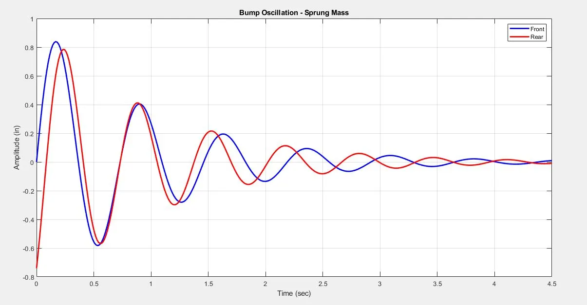
Therefore the revised frequency split is 13.33% (unaltered). Since, the revised split is unchanged the flat ride phenomenon is not affected.
Induced body pitch for the revised ride frequency values are:
Step 12: Re-evaluation of spring rates:
The revised spring rate values are as follows:
| Parameter | Unit | Front | Rear |
| Spring rate | lb/in | 205.25 | 282.50 |
Step 13: Recheck of the auxillary stiffness for the obtained spring rates:
Now, for the obtained spring rates the above workflow is maintained to check for the new auxillary roll stiffness values:
| Revised | Unit | Value |
| Front auxillary roll stiffness | % | 58.99 |
| Rear auxillary roll stiffness | % | 15.25 |
The obtained values are well within the constraints.
Step 14: Evaluation of ARB dimensions:
Further calculations are performed on the revised values.
Revised ARB contribution to roll stiffness:
For front axle:
`K_(ϕfarb) = 5028.462246` in-lb/deg
For rear axle:
`K_(ϕrarb) = 837.7878998` in-lb/deg
Roll rate due to Anti-roll bar:
For front axle:
`K_(farb) = (K_(ϕfarb)/(MR_(farb)^2*t^2))*(180/π)`
where,
`K_(ϕfarb) -` ARB contribution to roll stiffness (in-lb/deg)
`MR_(farb) -` ARB motion ratio (in/in)
`t -` Trackwidth (in)
`K_(farb) = 209.0941542` lb/in
For rear axle:
`K_(rarb) = 25.36753113` lb/in
Anti-roll bar diameter is calculated considering the bar to be solid and the material to be steel.
Diamter of anti-roll bar:
For front axle:
`OD = (((K_(farb)*((0.4422*A^2*B)+(0.2264*C^3)))/500000)^0.25)*25.4`
where,
`K_(farb) -` Roll rate due to Anti-roll bar (lb/in)
`A -`Virtual torque arm of arb (in)
`B -` Center length (in)
`C -` Physical torque arm (in)
`OD = 22.21105765 ~ 22.25` mm
For rear axle:
`OD = 12.55674731 ~ 12.75` mm
The obtained anti-roll bar dimensions are:
| Parameter | Unit | Front | Rear |
| ARB Diameter | mm | 22.25 | 12.75 |
STAGE 3:
ANTI CHARACTERISTICS OPTIMIZATION:
Pitch is the vehicle body angular displacement due to longitudinal load transfer as a result of net acceleration and braking of the vehicle.
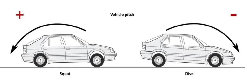
Anti characteristics of the suspension describe the longitudinal to vertical force coupling between the sprung and the unsprung masses and is determined from the slope of the swing arm in side view. This slope can be optimized for the desired pitch gradients by optmizing the hard point orientations in side view.
Target pitch gradients are:
| Parameter | Unit | Value |
| Acceleration pitch gradient | deg/g | 2.00 |
| Braking pitch gradient | deg/g | 1.00 |
Step 15: Evaluation of longitudinal load transfer, deflection (front and rear) under load and pitch gradient for 0% pitch compensation:
1. Longitudinal load transfer:
`ΔW = (W_t*h)/l`
where,
`W_t -` Weight of the vehicle (lb)
`h -` Cg height (in)
`l -` Wheelbase (in)
`ΔW = 607.1428571` lb/g
2. Deflection under load:
For front axle:
`Z_(df) = (ΔW)/(2*K_(rf)`
where,
`ΔW -` Weight transfer (lb/g)
`K_(rf) -` Front ride rate (lb/in)
`Z_(df) = 1.833953131` in/g
For rear axle:
`Z_(dr) = 1.851287224` in/g
3. Pitch gradient for 0% pitch compensation:
`ϕ_(p0) = (tan^-1((Z_(df)+Z_(dr))/l))*(180/π)`
where,
`Z_(df) -` Front axle deflection under load (in/g)
`Z_(dr) -` Rear axle deflection under load (in/g)
`l -` Wheelbase (in)
`ϕ_(p0) = 2.153564029` deg/g
Step 16: Side view geometry set up:
For swing arm horizontal distance, 70 to 120 inches is a reasonable starting point. From there on, the pitch gradients were optimised to the target value by keeping the swing arm vertical distance to be a constant value of 15 inches and iterating the rear swing arm horizontal distance with steps of 0.5 inches untill the target pitch gradients were achieved.
Geometry set up:
| Parameter | Unit | Front | Rear | |||
| Vertical distance of IC from contact patch_e | in | 12.5 | 20 | |||
| Horizontal distance of IC from contact patch_d | in | 70 | 110 | |||
Note: There are numerous iterative ways and geometric setups possible to achieve the target pitch gradients. It is essential though to come up with the best possible compromise.
Step 17: Evaluation of acceleration pitch gradient:
The target vehicle is a 4WD sedan with an independent suspension. For an independent suspension, the side view swing arm height is calculated from the wheel center since the torque is reacted by the subframe and the chassis body. (this is because the differential is mounted on the subframe)
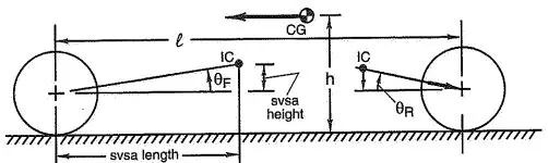
The actual anit-squat angle at the rear and the actual anti-lift angle at the front ar calculated as follows:
Actual anti-squat angle:
`θ_(aas) = (tan^-1((e_r-R_(rl))/d_r))*(180/π)`
where,
`e_r -` Vertical distance of IC from rear contact patch (in)
`d_r -` Horizontal distance of IC from rear contact patch (in)
`R_(rl) -` Rear tire loaded radius (in)
`θ_(aas) = 4.019722572` deg
Actual anti-lift angle:
`θ_(aal) = (tan^-1((e_f - R_(fl))/d_f))*(180/π)`
where,
`e_f -` Vertical distance of IC from front contact patch (in)
`d_f -` Horizontal distance of IC from front contact patch (in)
`R_(fl) -` Front tire loaded radius (in)
`θ_(aal) = 0.188256884` deg
Ideal anti-squat and anti-lift angle:
`θ_(ideal) = (tan^-1(h/l))*(180/π)`
where,
`h -` Cg height (in)
`l -` Wheelbase (in)
`θ_(ideal) = 9.84113176` deg
Anti-squat %:
`AS_% = (((1-ϕ_d)*θ_(aas))/θ_(ideal))*100`
where,
`ϕ_d -` Front drive ratio
`θ_(aas) -` Actual anti-squat angle (deg)
`θ_(ideal) -` Ideal anti-squat angle (deg)
`AS_% = 12.25384235 %`
Anti-lift %:
`Al_% = ((ϕ_d*θ_(aal))/θ_(ideal))*100`
where,
`ϕ_d -` Front drive ratio
`θ_(aal) -` Actual anti-lift angle (deg)
`θ_(ideal) -` Ideal anti-lift angle (deg)
`AL_% = 1.339071784 %`
Deflection with the new anti-pitch geometry setup:
For front axle:
`Z_(fapd) = (Z_(df)*(100-AL_%))*0.01`
where,
`Z_(df) -` Deflection under load with zero% pitch compensation (in/g)
`AL_%` Anti-lift (%)
`Z_(fapd) = 1.809395182` in/g
For rear axle:
`Z_(rapd) = (Z_(dr)*(100 - AS_%))*0.01`
where,
`Z_(dr) -` Deflection under load with zero% pitch compensation (in/g)
`AS_% -` Ant-squat %
`Z_(rapd) = 1.624433406` in/g
Acceleration pitch gradient:
`ϕ_(pa) = (tan^-1((Z_(fapd)+Z_(rapd))/l))*(180/π)`
where,
`Z_(fapd) -` Front deflection under load with pitch compensation (in/g)
`Z_(rapd) -` Rear deflection under load with pitch compensation (in/g)
`l -` Wheelbase (in)
`ϕ_(pa) = 2.006769677` deg/g
Step 18: Evaluation of braking pitch gradient:
The target vehicle is a 4WD sedan with an independent suspension and employed with an outboard braking system. For an outboard braking system the brake torques are reacted at the the ground. Therefore for braking pitch gradient the swing arm vertical height is considered from contact patch.
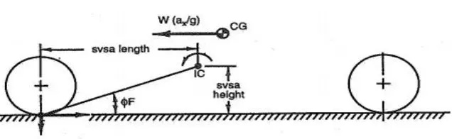
Actual anti-dive angle:
`θ_(aad) = (tan-^1(e_f/d_f))*(180/π)`
where,
`e_f -` Vertical distance of IC from front contact patch (in)
`d_f -` Horizontal distance of IC from front contact patch (in)
`θ_(aad) = 10.12467166` deg
Actual anti-lift angle:
`θ_(aal) = (tan^-1(e_r/d_r))*(180/π)`
where,
`e_f -` Vertical distance of IC from rear contact patch (in)
`d_f -` Horizontal distance of IC from rear contact patch (in)
`θ_(aal) = 10.30484647` deg
Ideal anti-dive and anti-lift angle:
`θ_(ideal) = (tan^-1(h/l))*(180/π)`
where,
`h -` Cg height (in)
`l -` Wheelbase (in)
`θ_(ideal) = 9.84113176` deg
Anti-dive %:
`AD_% = ((ϕ_b*θ_(aad))/θ_(ideal))*100`
where,
`ϕ_b -` Front brake ratio
`θ_(aad) -` Actual anti-dive angle (deg)
`θ_(ideal) -` Ideal anti-dive angle (deg)
`AD_% = 61.72870297%`
Anti-lift %:
`Al_% = (((1-ϕ_b)*θ_(aal))/θ_(ideal))*100`
where,
`ϕ_b -` Front brake ratio
`θ_(aal) -` Actual anti-lift angle (deg)
`θ_(ideal) -` Ideal anti-lift angle (deg)
`AL_% = 41.88480236%`
Deflection with the new anti-pitch geometry setup:
For front axle:
`Z_(fbpd) = (Z_(df)*(100-AD_%))*0.01`
where,
`Z_(df) -` Deflection under load with zero% pitch compensation (in/g)
`AD_% -` Ant-dive %
`Z_(fapd) = 0.70187765` in/g
For rear axle:
`Z_(rbpd) = (Z_(dr)*(100-AL_%))*0.01`
where,
`Z_(dr) -` Deflection under load with zero% pitch compensation (in/g)
`AL_% -` Ant-lift %
`Z_(rapd) = 1.075879229`in/g
Braking pitch gradient:
`ϕ_(pb) = (tan^-1((Z_(fbpd)+Z_(rbpd))/l))*(180/π)`
where,
`Z_(fbpd) -` Front deflection under load with pitch compensation (in/g)
`Z_(rbpd) -` Rear deflection under load with pitch compensation (in/g)
`l -`Wheelbase (in)
`ϕ_(pb) = 1.039253015` deg/g
Step 19: Acceleration and braking pitch gradients check:
| Parameter | Unit | Target Value | Achieved Value | Deviation |
| Acceleration pitch gradient | deg/g | 2.00 | 2.00 | 0% |
| Braking pitch gradient | deg/g | 1.00 | 1.03 | 3% |
Since the achieved values of acceleration pitch gradient and braking pitch gradient are with the deviation value of 5%, the selected geometric setup is justified.
Step 20: Evaluation of pitch compensation:
Pitch compensation for acceleration pitch gradient:
`%PC_a = ((ϕ_(p0)-ϕ_(pa))/ϕ_(p0))*100`
where,
`ϕ_(p0) -` Pitch gradient for 0% pitch compensation
`ϕ_(pa) -` Acceleration pitch gradient (deg/g)
`%PC_a = 6.816344895 %`
Pitch compensation for braking pitch gradient:
`%PC_b = ((ϕ_(p0)-ϕ_(pb))/ϕ_(p0))*100`
where,
`ϕ_(p0) -` Pitch gradient for 0% pitch compensation
`ϕ_(pb) -` Braking pitch gradient (deg/g)
`%PC_b = 51.7426461 %`
Conclusion:
The adopted work flow was dedicated to set component level targets providing a baseline setup of springs, anti-roll bar and geometry for the target vehicle (4WD sedan with a Macpherson strut assembly at the front end and a multilink setup at the rear) to achieve the specified system level targets.
Results:
| Parameter | Unit | Front | Rear |
| Spring rate | lb/in | 205.25 | 282.50 |
| Anti-roll bar diameter | mm | 22.25 | 12.75 |
| Vertical distance of IC from contact patch_e | in | 12.5 | 20 |
| Horizontal distance of IC from contact patch_d | in | 70 | 110 |
| Parameter | Unit | Target Value | Achieved Value | Deviation |
| Front ride frequency | Hz | 1.35 | 1.37 | 1.48% |
| Roll gradient | deg/g | 3.80 | 3.80 | 0% |
| Acceleration pitch gradient | deg/g | 2.00 | 2.00 | 0% |
| Braking pitch gradient | deg/g | 1.00 | 1.03 | 3% |
Therefore the system level targets are well within range.
Calculations link:
https://drive.google.com/file/d/1PeMepbp6__PGeBMLVul8_BdZHmMU7vy-/view?usp=sharing
References:
1] Race car vehicle dynamics, W. F. Milliken and D. L. Milliken, SAE, Warrendale, PA 15096-0001 USA, ISBN 1-56091-526-9
2] Optimum G, Tech Tips: Springs & Dampers, Part One, 6450 S. Quebec St., Ste. 5-28 Centennial, CO 80111, USA