FINAL INDEPENDENT PROJECT
Design and Assembly of a V6 Engine Model Using SolidWorks
1. OBJECTIVE
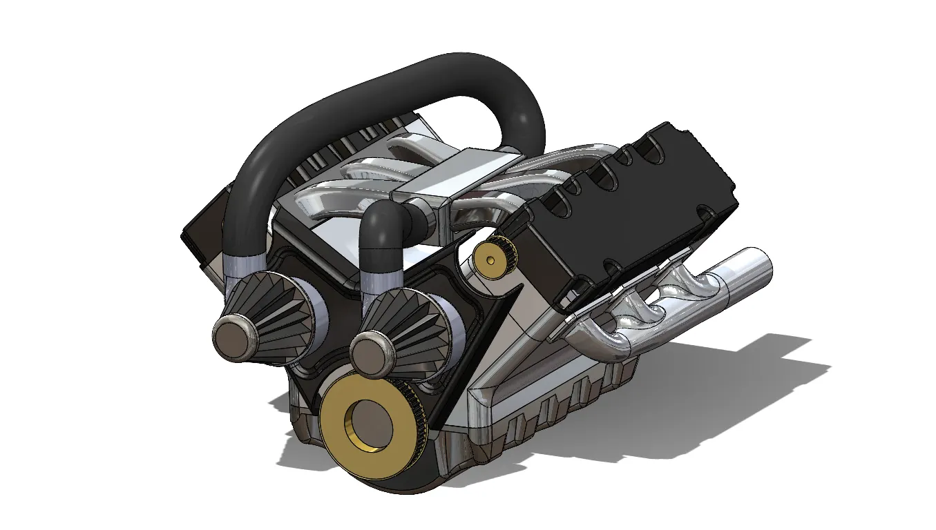
To design and assemble every part of a V6 engine, including the engine block, cylinder head, pistons, crankshaft, camshaft, timing system, and intake manifold, using SolidWorks to produce a realistic and detailed model.
2. INTRODUCTION
In order to produce an accurate and useful V6 engine model, distinct engine components will be built and assembled in this project. SolidWorks, a number of sophisticated CAD tools, and rendering techniques were used in the development of the model. Every component blend in well with the finished assembly.
3. DESIGN METHODOLOGY
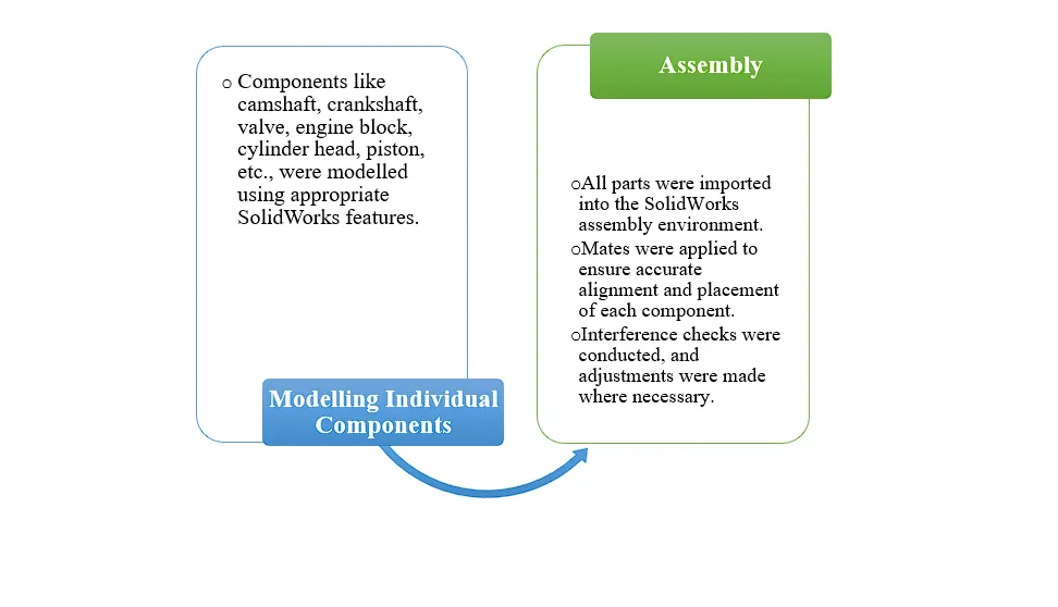
The following steps were included in the assembly process:
i. Modelling Individual Components
- Defining the component arrangement and foundation design.
- Drawing limited sketches for every component.
- The geometry is defined using surface extrude, surface loft,
- To define the solid bodies, features like Swept Loft, Cut Extrude, and Boss Extrude are used.
- Solid bodies are created by knitting and merging surfaces.
- Referring to the fundamental design.
ii. Assembly
- Aligning and assembling the parts in SolidWorks with the proper mates.
- Checking for interference between components to guarantee correct fit.
- Modifying to avoid interference and guarantee that moving parts operate smoothly.
4. DESCRIPTION
4.1. Engine Block
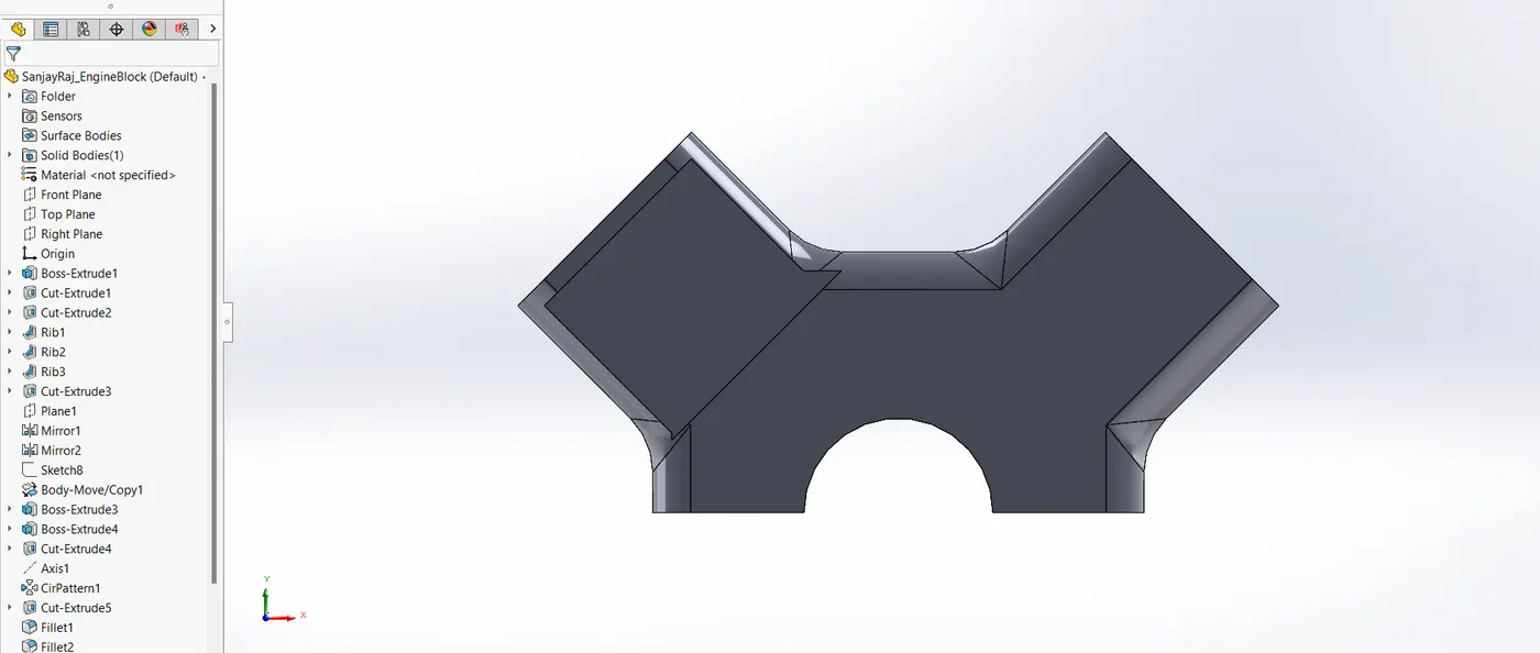
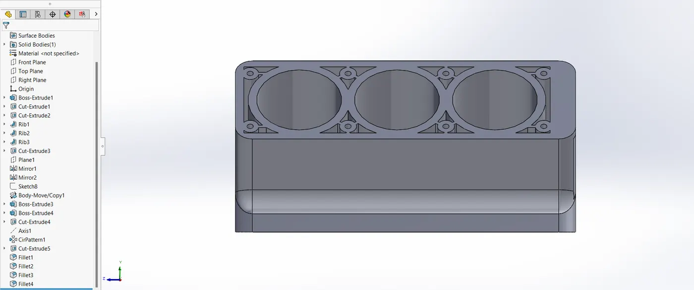
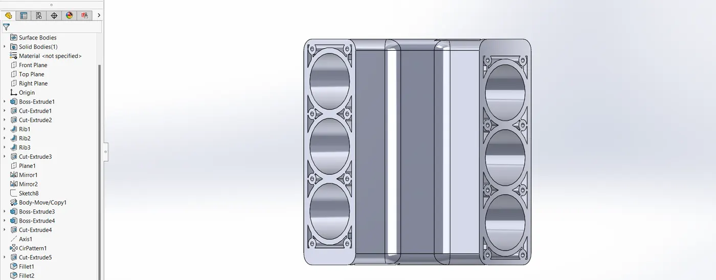
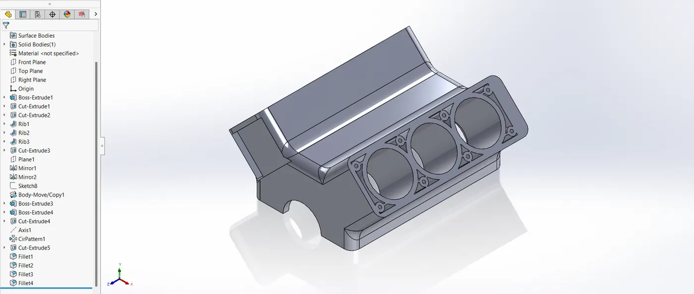
The V6 engine's main structural element is the engine block. It supports the engine's overall operation and houses the pistons and other moving parts.
CAD Modelling Process
- To add thickness, solid modelling techniques like Shell, Cut, and Boss extrusion are used to form the engine block.
- To define borders and establish different channels for the flow of coolant and oil, additional features such as Fillet, Chamfer, and Linear Patterns were utilized.
4.2. Piston
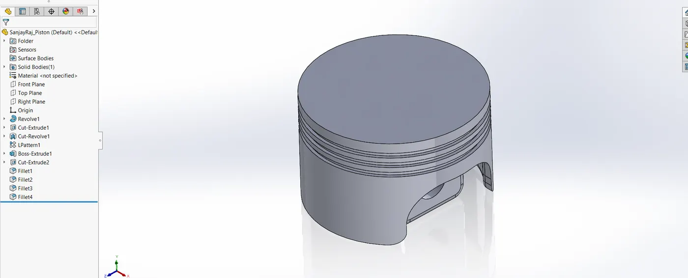
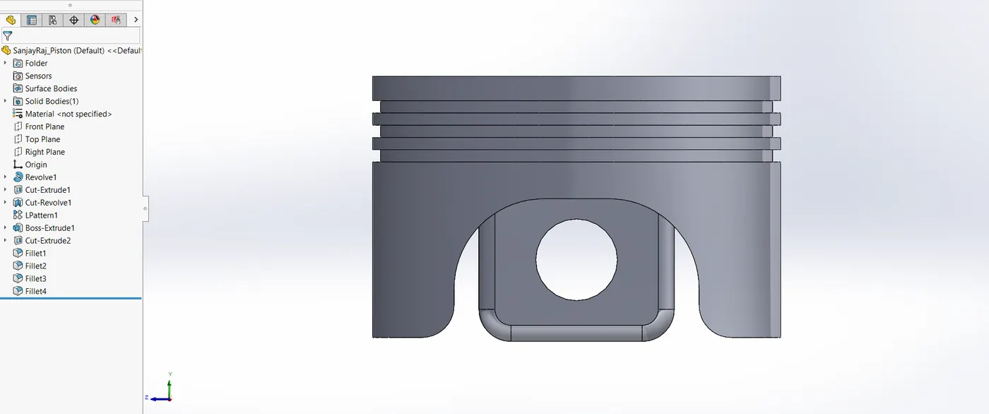
In order to transform the pressure from combustion into mechanical energy, pistons are essential. The design prioritizes weight reduction, strength, and efficiency.
CAD Modelling Process
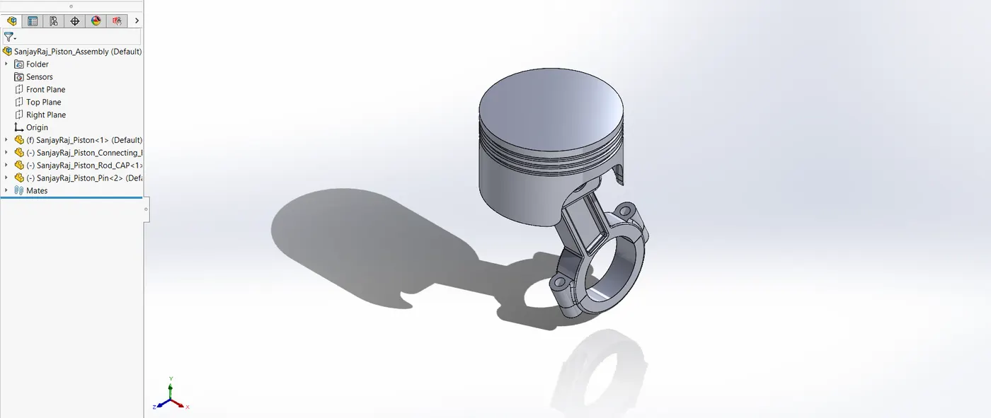
- The piston shape was created using extrude boss features and revolve. Piston rings and other parts were replicated using patterns. The addition of chamfer and fillet features improved the part's longevity and smoothed its edges.
- Boss extrude, Cut-Extrude, Mirror and fillet features are then used to construct the piston connecting rod.
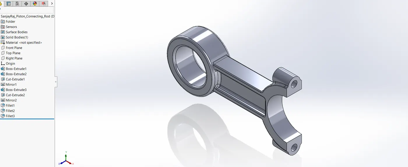
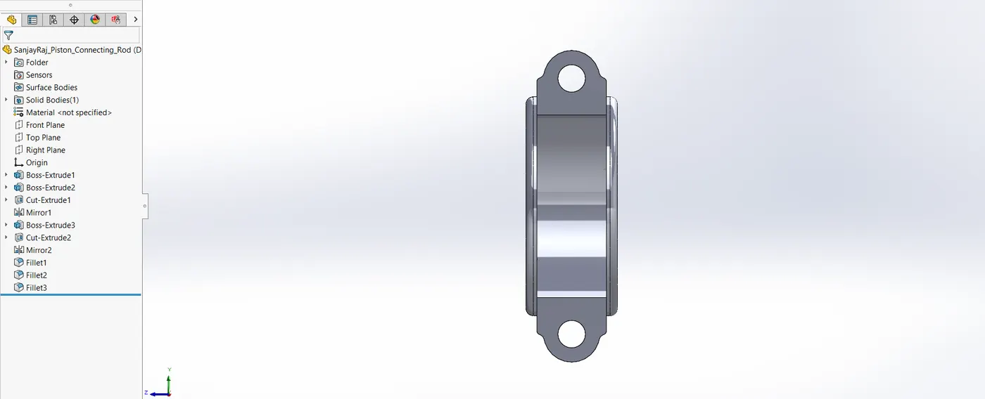
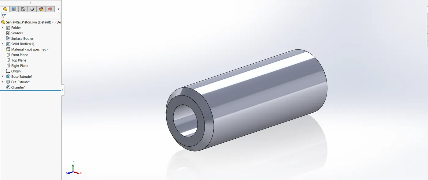
- The piston pin is made next, followed by the piston rod cap. Boss extrude, cut extrude and chamfer are the features used to create Piston pin.
- Boss extrude, cut extrude, mirror, fillet and hole wizard are used for the creation of Connecting rod cap.
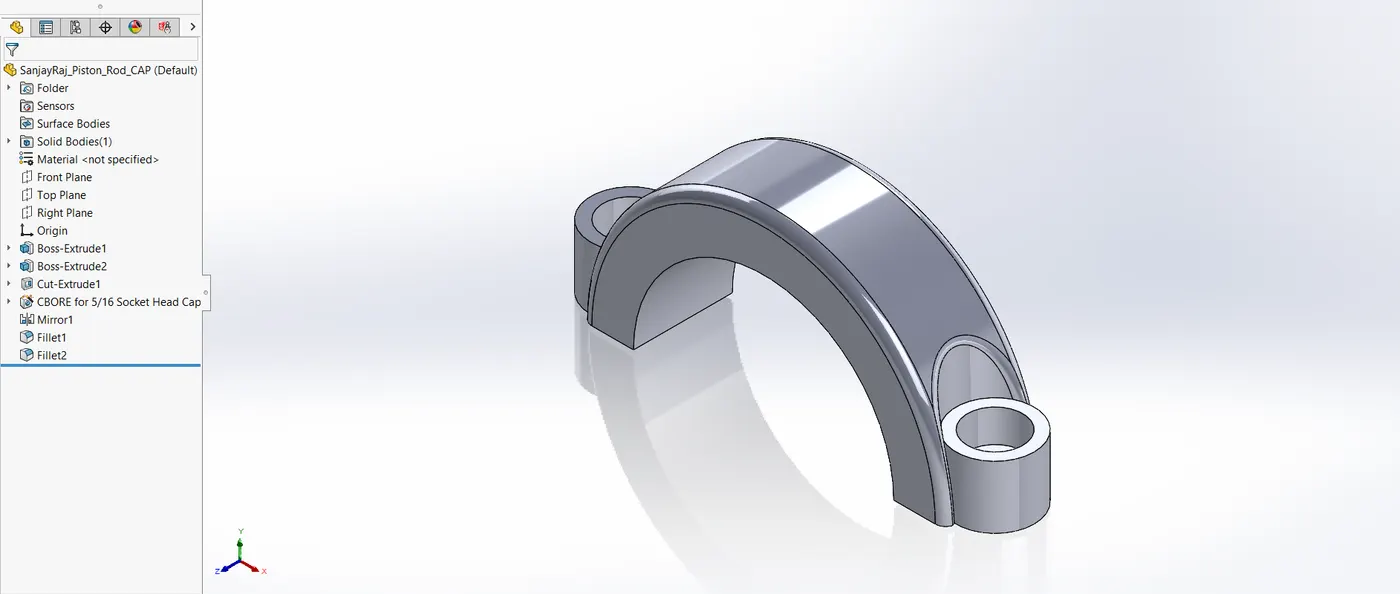
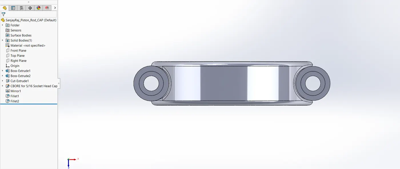
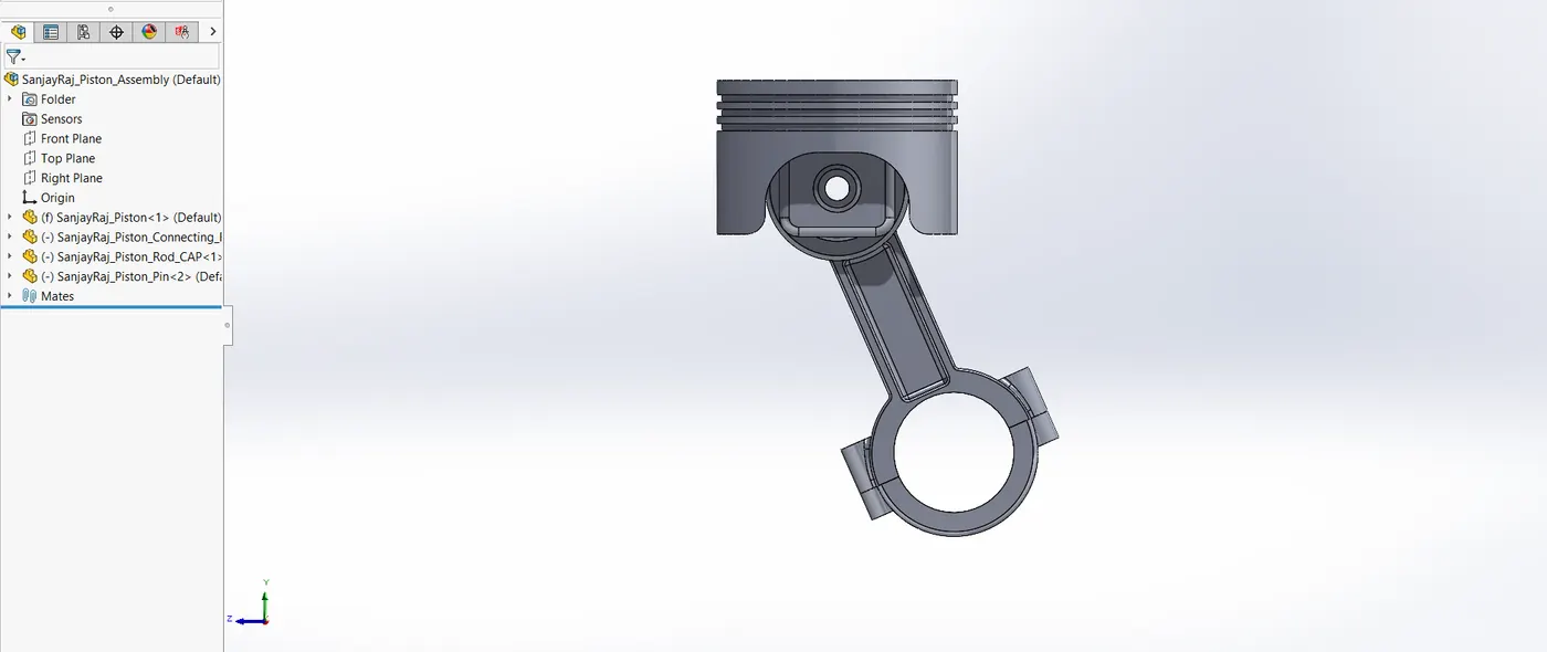
- Following its individual creation, these were all put together to form the piston Assembly.
4.3. Crankshaft
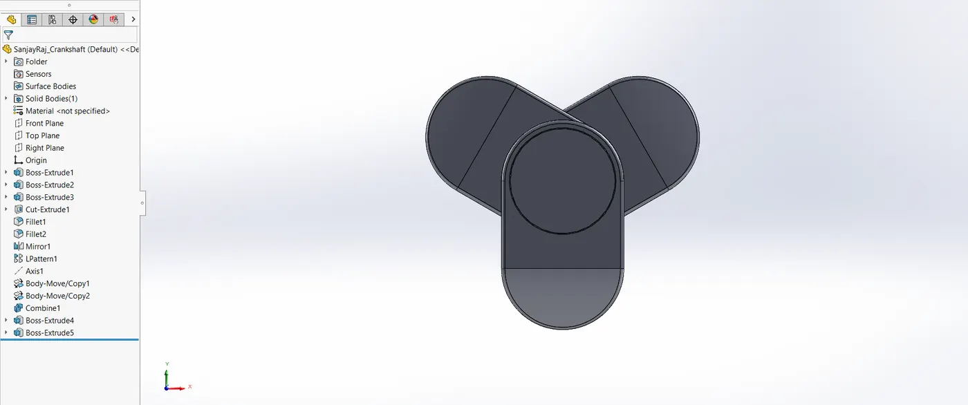
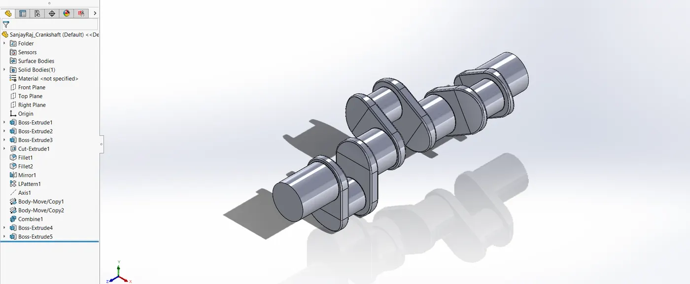
The pistons linear motion is transformed into rotational energy by the crankshaft. Strength and balance are guaranteed by the crankshaft design for seamless engine running.
CAD Modelling Process
- The Extrude tool was used to create the crankshaft and linear pattern.
- To improve the design and guarantee correct fit within the engine block, further features including cut extrude, fillet, and chamfer were employed.
4.4. Camshaft
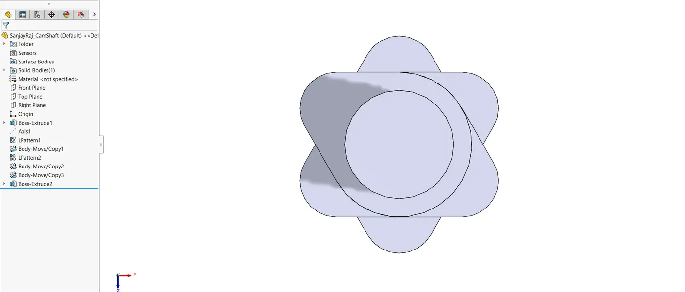
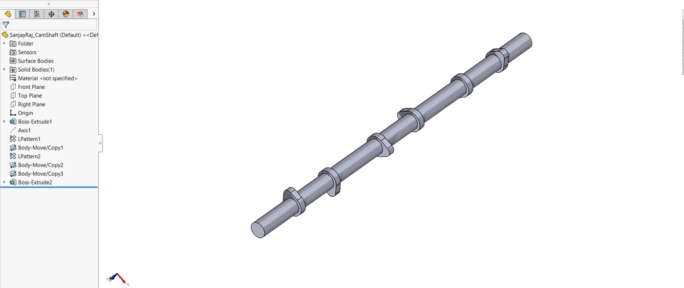
The camshaft regulates the engine's valves' opening and shutting. Its design calls for exact crankshaft alignment and timing.
CAD Modelling Process
- The camshaft was modelled using a mix of Linear pattern, copy/move and Boss Extrude.
4.5. Intake Manifold
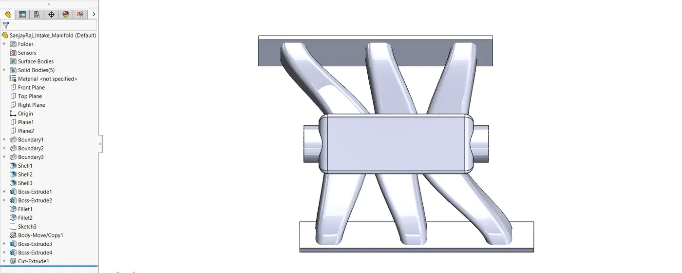
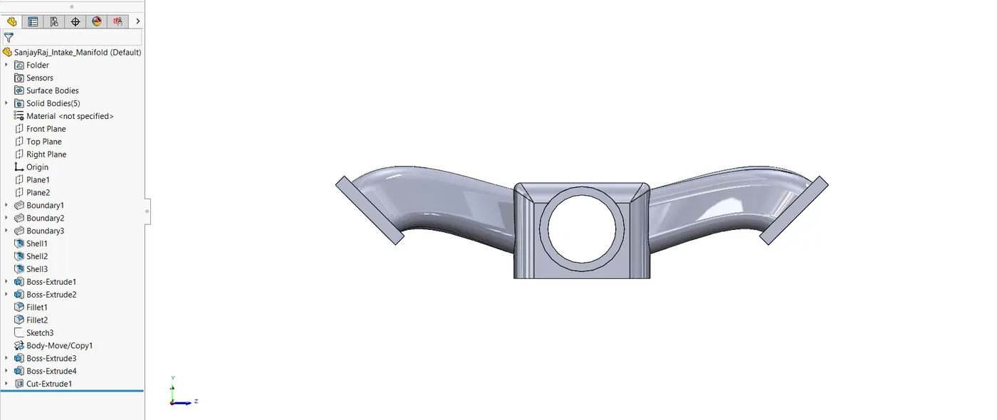
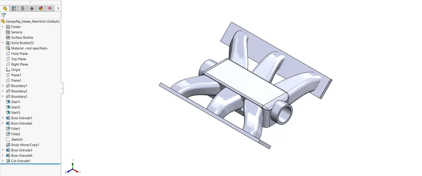
The engine's cylinders receive the air-fuel mixture from the intake manifold for burning.
CAD Modelling Process
- Boundary Boss and Boss Extrude were used to model the intake manifold and specify the intake runners.
- To improve airflow efficiency, shell and fillet were used to smooth the internal flow channels.
4.6. Exhaust Manifold
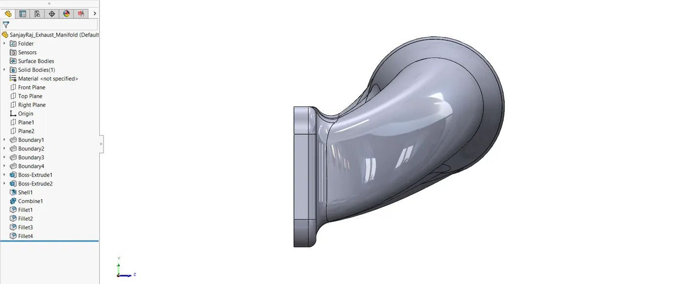
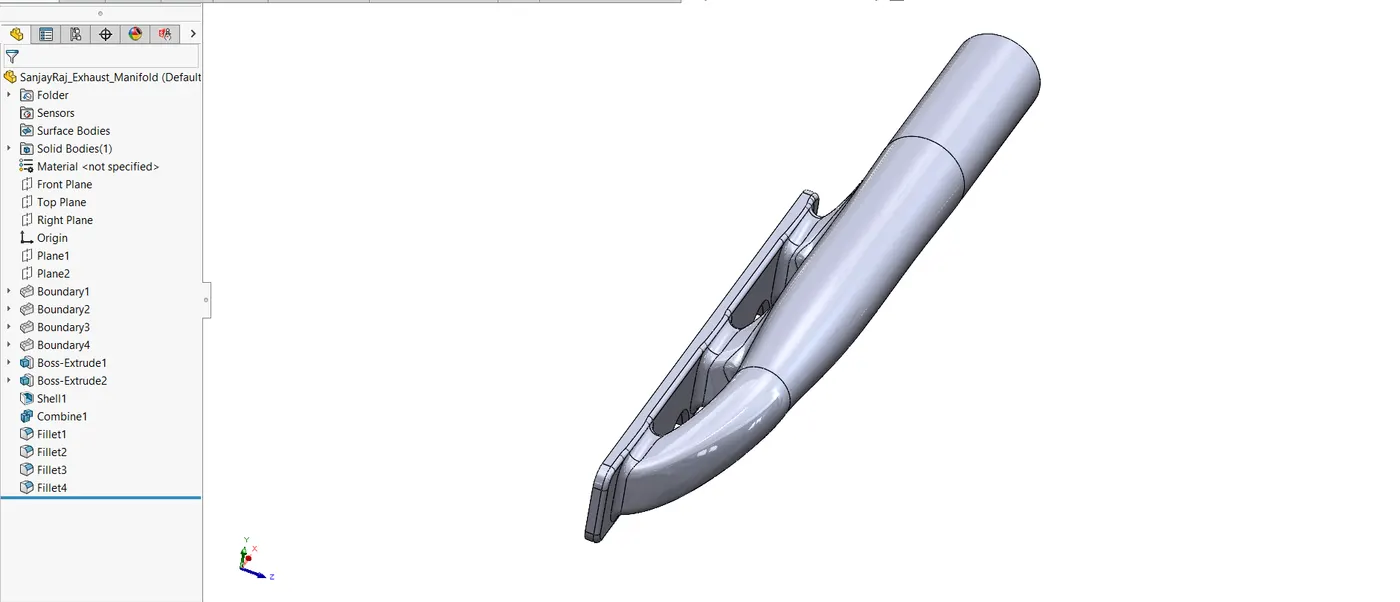
Exhaust gases are sent from the cylinders to the exhaust system via the exhaust manifold. Maintaining engine performance and reducing exhaust restrictions depend heavily on its design.
CAD Modelling Process
- In order to accommodate exhaust flow, the exhaust manifold was developed using similar approaches as the intake manifold.
- Next, mirror part feature is used to create another Exhaust manifold.
4.7. Air Filter
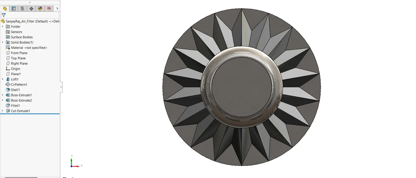
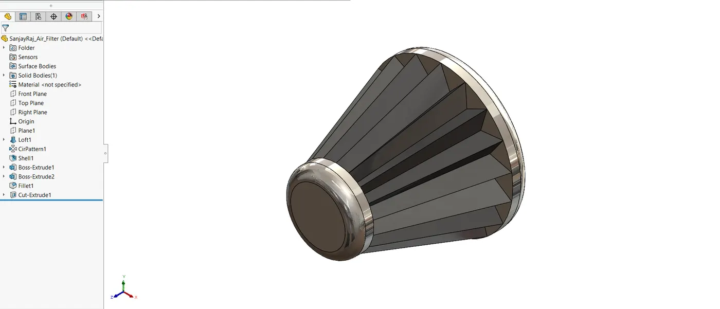
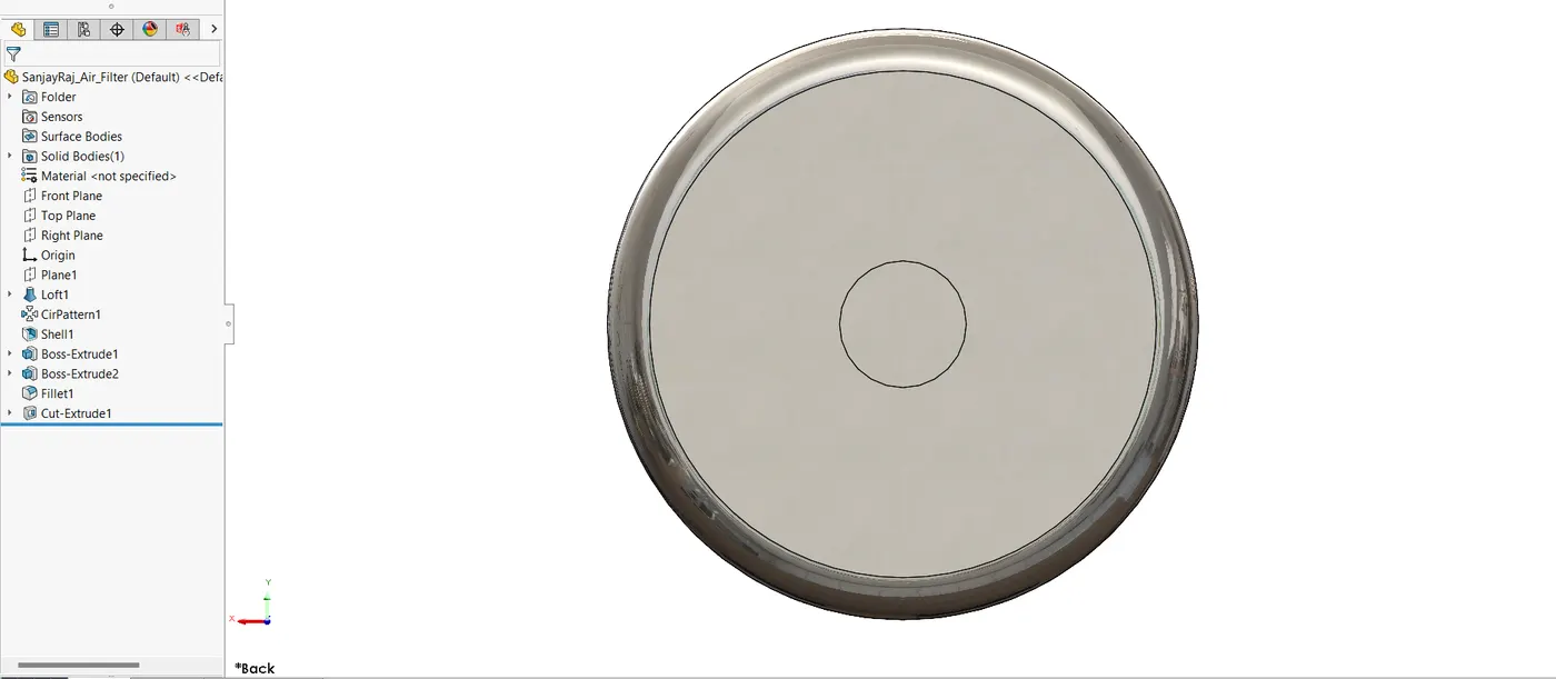
For the engine to receive clean air for combustion, the air filter is an essential part. It keeps particles out of the engine that could harm it.
CAD Modelling Process
- Boss Extrude, loft, circular pattern and Cut Extrude were used to model the air filter in order to construct the required filter housing and flow channels.
- The filter material was represented by a perforated surface feature.
4.8. Belt wheels
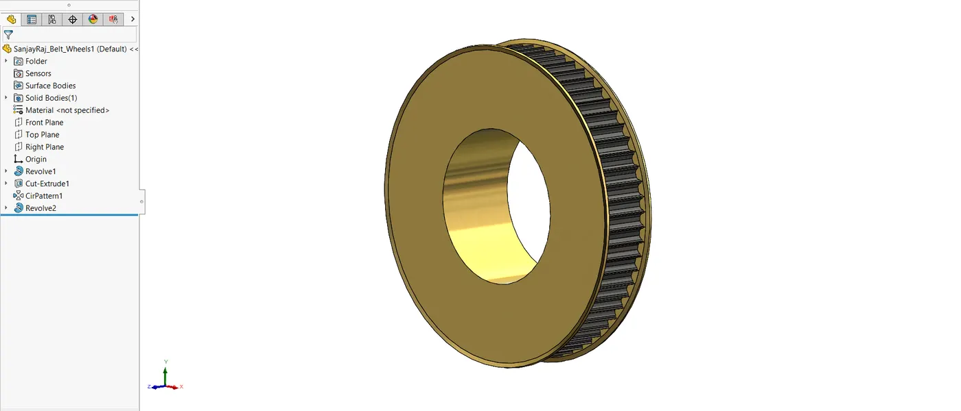
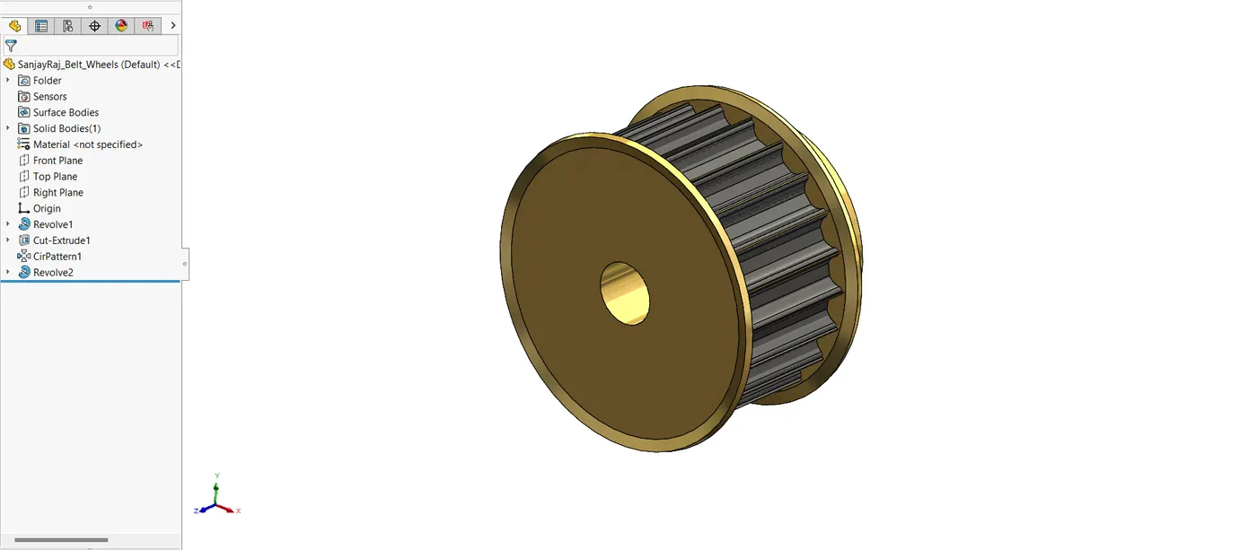
The engine uses belt wheels to power a number of parts, including camshaft and crankshaft.
CAD Modelling Process
- A symmetrical, circular design that interfaces with the timing belt was created by modelling the belt wheels using the Revolve, Circular Pattern and Cut extrude capabilities.
4.9. Camshaft and Crankshaft Bush
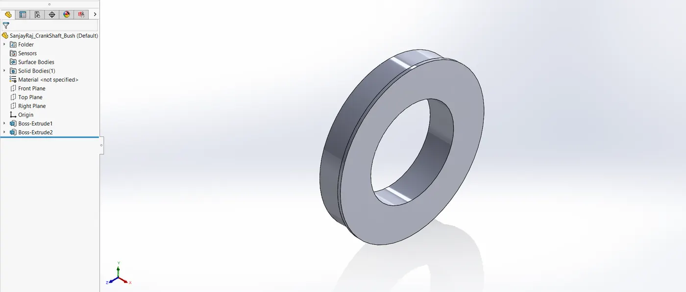
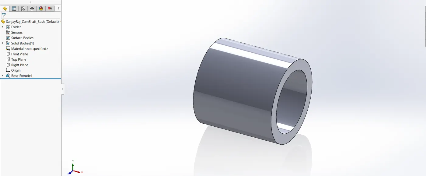
In addition to supporting the Shaft, the bush guarantees smooth rotation inside the cylinder head.
CAD Modelling Process
- Boss Extrude characteristic was used in the creation of the bush in order to precisely fit and define its shape.
4.10. Camshaft Retainer
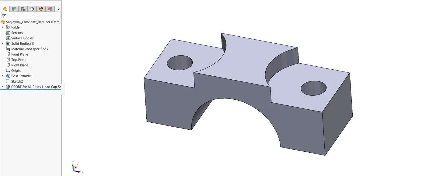
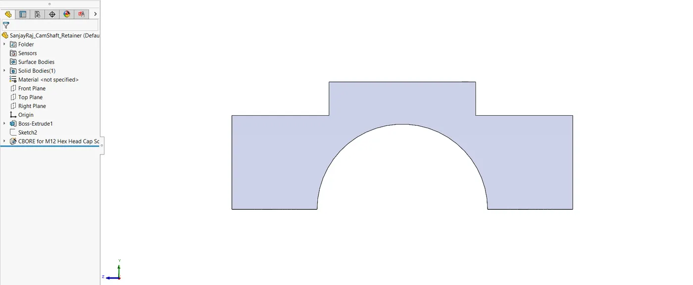
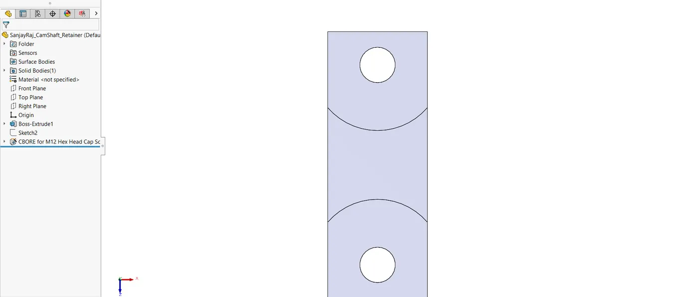
The camshaft is held in place inside the engine block by the camshaft retainer.
CAD Modelling Process
- Hole wizard and Boss Extrude features were used in the construction of the camshaft retainer to guarantee a tight fit around the camshaft.
4.11. Cylinder Head
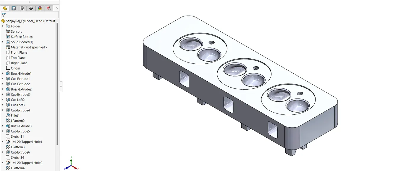
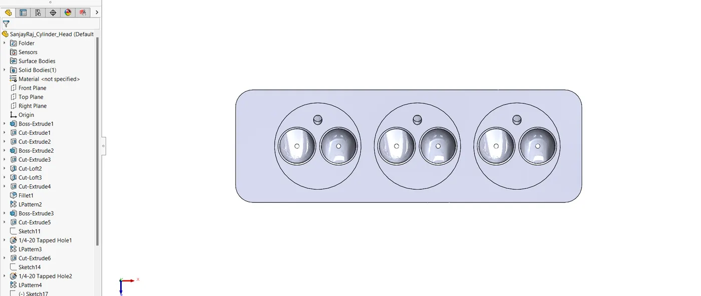
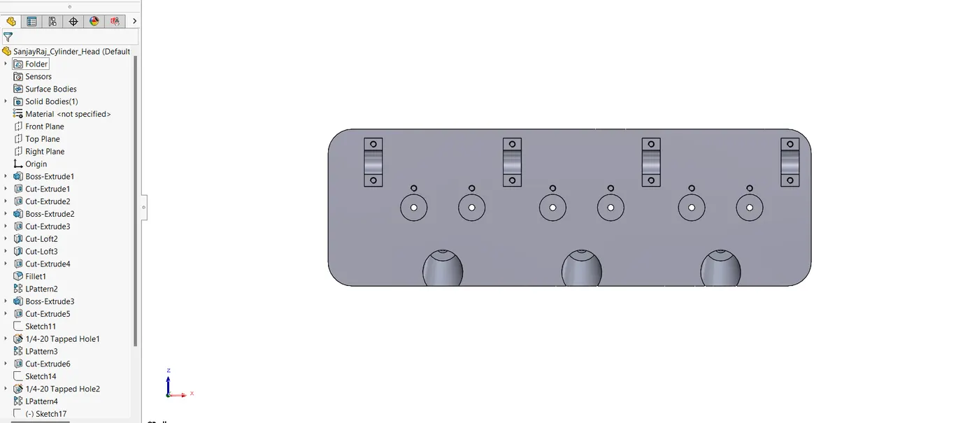
One essential portion that houses the camshaft, valves, and other vital engine components is the cylinder head.
CAD Modelling Process
- Boss Extrude, Cut Extrude, cut loft, fillet, linear pattern and Hole Wizard characteristics were used to establish the required coolant and oil flow channels in the cylinder head.
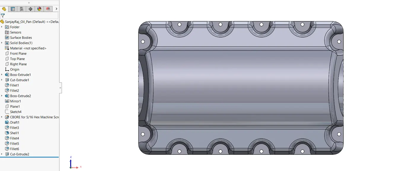
4.12. Oil Pan
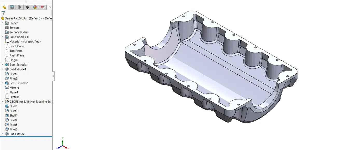
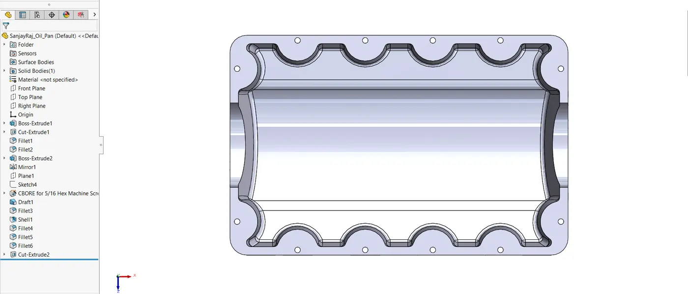
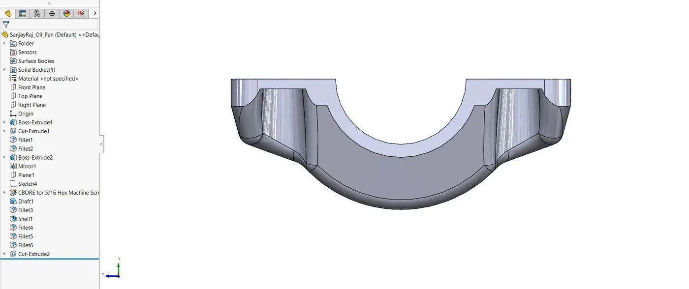
Engine oil is gathered and kept in the oil pan. It is essential for cooling and lubricating.
CAD Modelling Process
- Boss Extrude and Shell characteristics were used in the construction of the oil pan to create an exact enclosure that fits the engine block's bottom.
4.13. Rocker Arm
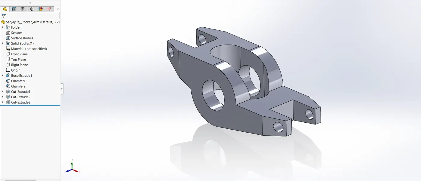
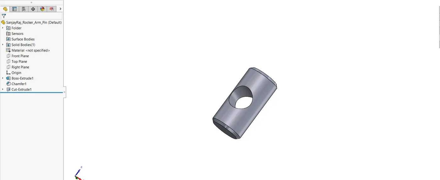
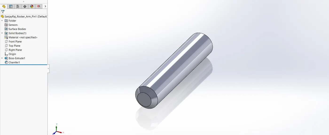
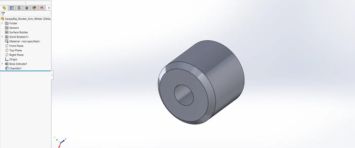
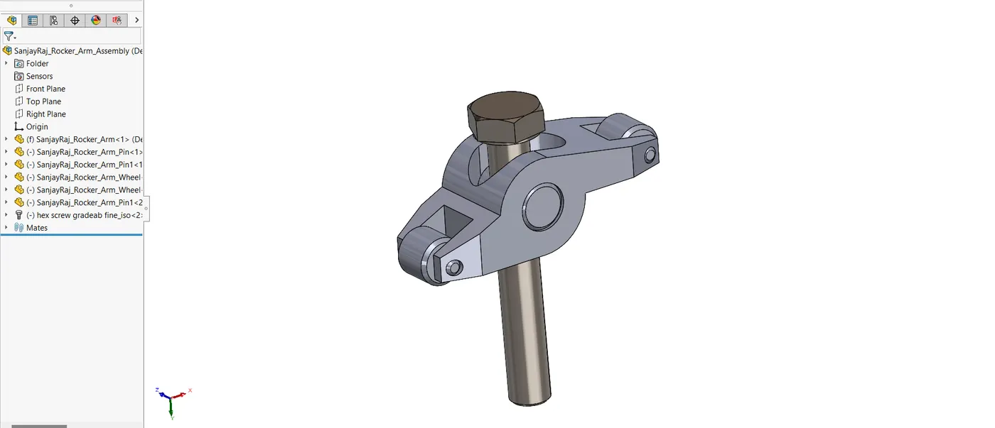
The camshaft's rotational motion is transformed into the vertical motion needed to open the valves by the rocker arm. To swivel the rocker arm for valve action, utilize the rocker arm pin. The rocker arm wheel facilitates the rocker arm's smooth action.
CAD Modelling Process
- Boss Extrude, chamfer and cut extrude features were used to determine the shape and motion of the rocker arm.
- Boss extrude, chamfer and Cut Extrude were used to model the pin in order to guarantee exact fitting with the engine and rocker arm parts.
- Boss extrude was used in the design of the wheel to create a cylindrical shape with the necessary qualities for smooth rotation.
- Mates were used to define the relative motion of the rocker arm components as they were built.
4.14. Rocker Spring
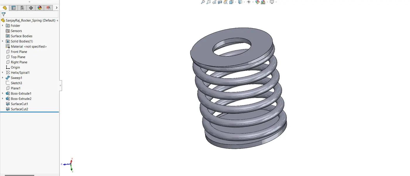
After the valve is operated, the rocker spring makes sure the rocker arm returns to its resting position.
CAD Modelling Process
- To replicate the proper spring action, the Helix/spiral, sweep, boss extrude and Surface cut feature was used to generate the spring.
4.15. Turbo
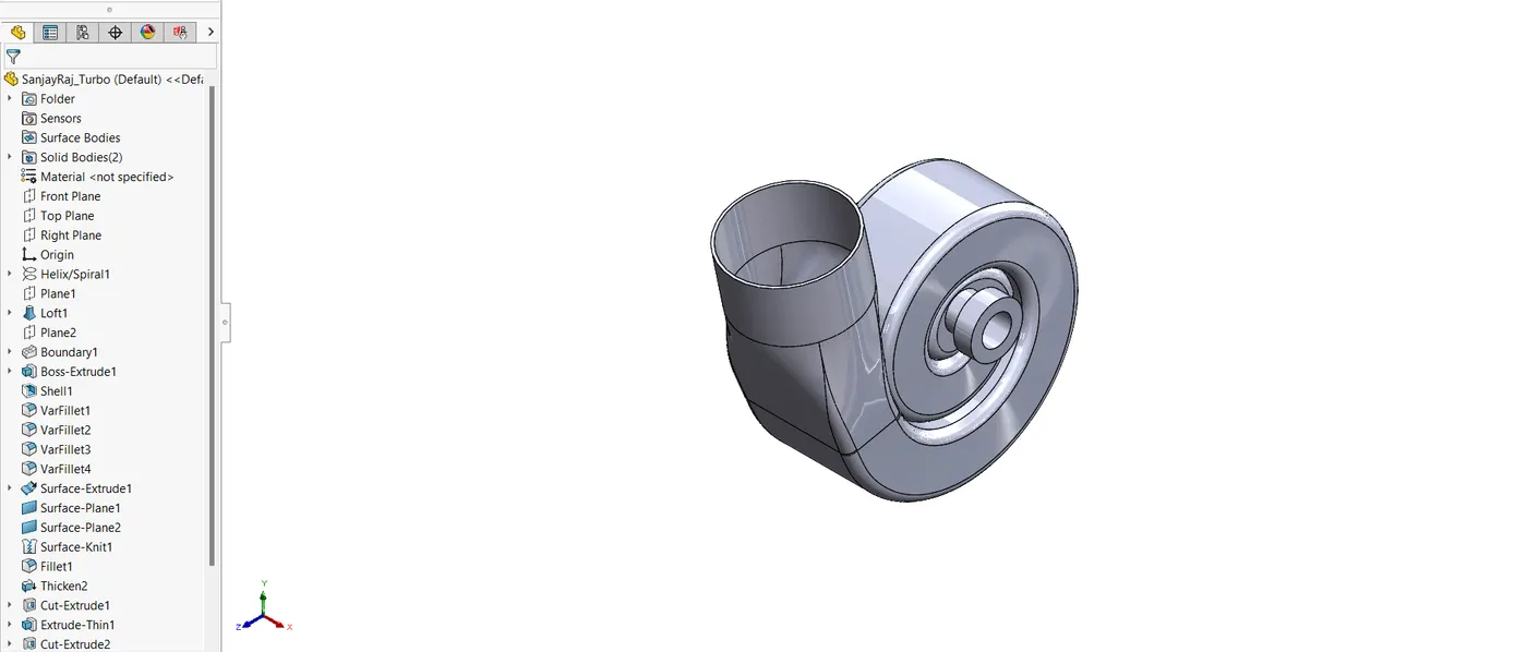
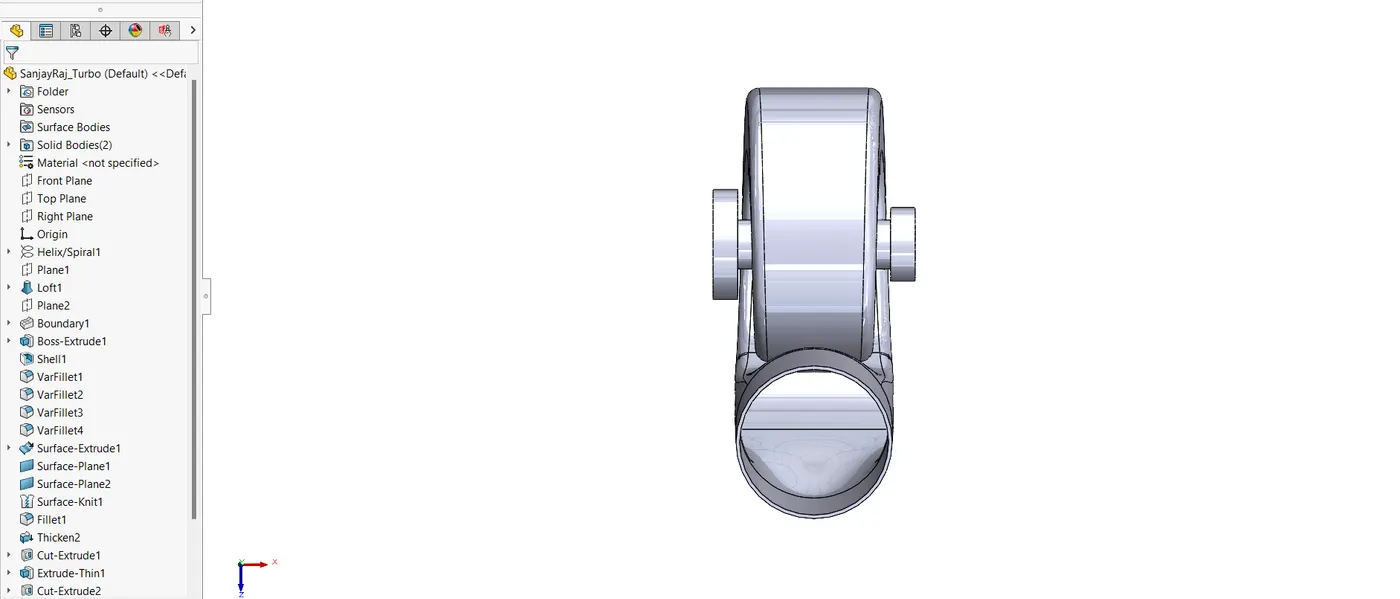
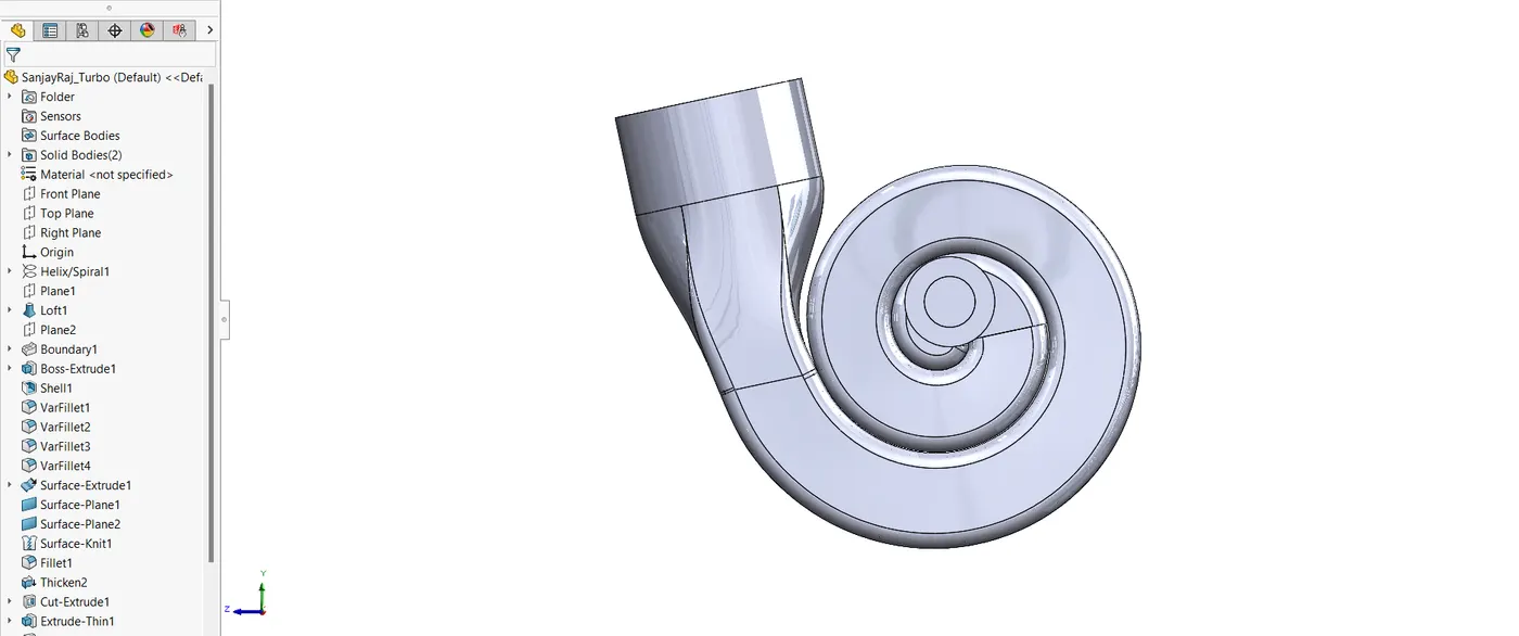
By pumping more air into the cylinders, the turbocharger improves engine performance.
CAD Modelling Process
- Loft, boundary, boss extrude, shell, surface extrude, surface knit and cut extrude features were used to represent the turbo's intake and exhaust parts.
4.16. Valve
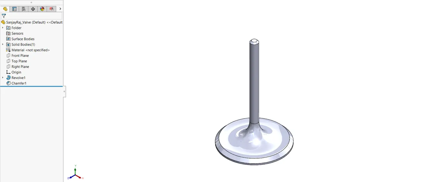
Air and exhaust gas flow into and out of the engine's cylinders are managed by the valve.
CAD Modelling Process
- To get the right shape for accurate valve operation, the valve was made using Revolve and chamfer.
4.17. Valve Cover
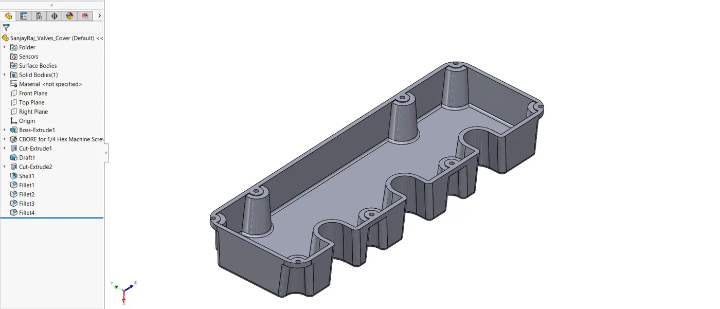
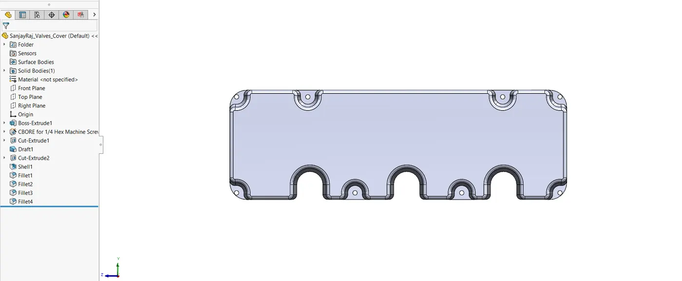
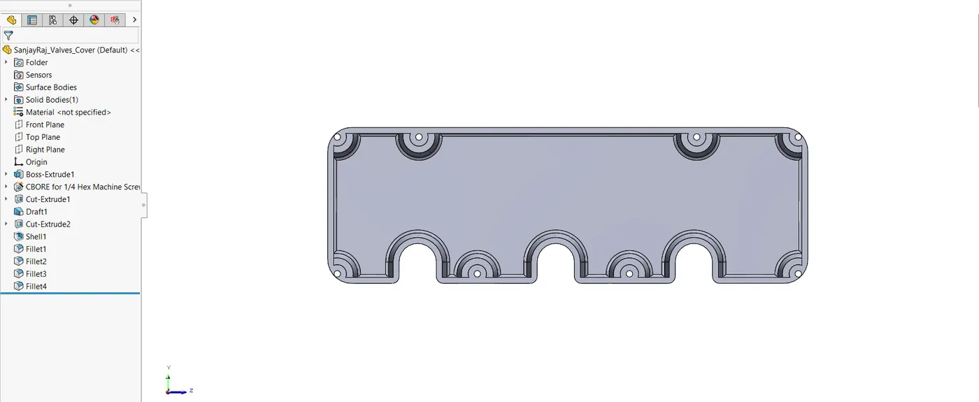
The valve cover closes the engine's top and shields the valve mechanism.
CAD Modelling Process
- To fit over the engine parts, the valve cover was made using Boss Extrude, shell, shell and Cut Extrude.
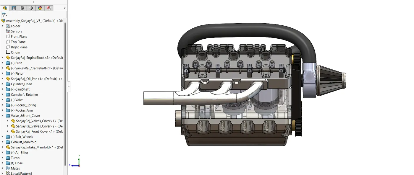
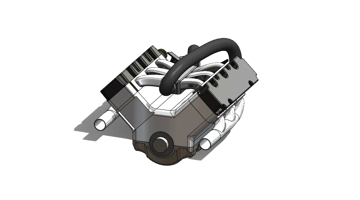
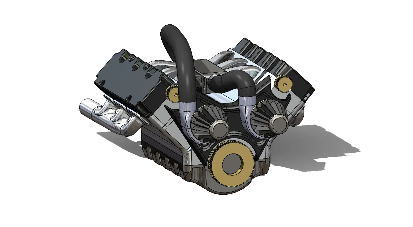
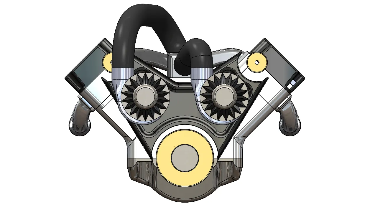
4.18. Engine Assembly
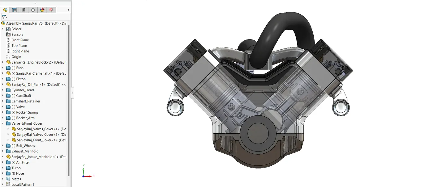
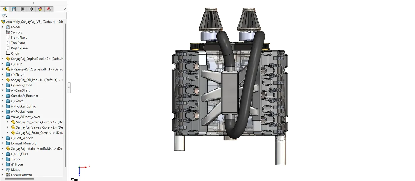
The finished V6 engine is the result of the final assembly of every component.
CAD Modelling Process
- The engine was put together with the right mates and alignments, guaranteeing that every component moved and positioned correctly.
5. CONCLUSION
SolidWorks was used to effectively construct and assemble the V6 engine model. The ability of CAD software to handle intricate engineering tasks was demonstrated by the design and integration of each component into the finished assembly.