FINAL INDEPENDENT PROJECT
Design, Assembly and Rendering of a Stirling Engine using SolidWorks and SolidWorks Visualize
Objective:
Design the parts of the Stirling Engine
Assemble the parts in solidworks assembly.
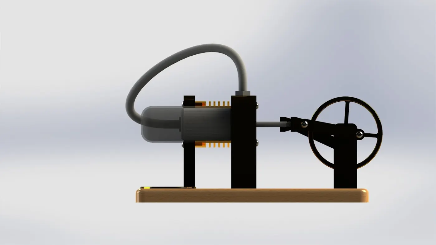
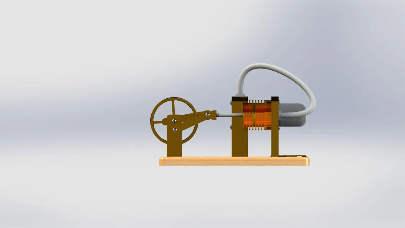
Render a high quality image using photoview 360 and SolidWorks Visualize.
Software Used:
SolidWorks 2023
SolidWorks is a parametric modeling software used for making/Designing models in industries such as automobile, aerospace, etc. The software is parametric, which means the model can be altered or modified at any given time. The design of the model changes with the alterations made in the part while modeling.
Motivation for the Project:
I'm a design engineer specializing in mechanical products, with over 5 years of experience in CAD. So let's build a fully-working model of Stirling Engine in SolidWorks. I will build all the parts that make up this unique design of a heat engine, and then, I will combine them together in a moving assembly that showcases exactly how the engine works.
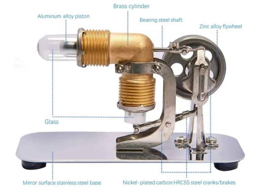
You've probably heard of internal combustion engines. These are very common engines in the modern world. And typically you find them in things like cars, trucks, aircraft, power generators, all sorts of different applications. And what they have in common is that they burn fuel to create heat that gives a power output. Sterling engines also use heat to create an output, but they're different to typical car engines because they're actually external combustion engines. So whereas a car engine typically burns fuel within the cylinder internally, the Stirling engine actually burns fuel outside of the cylinder externally. Both types of engines use heat energy to make gases expand and power the engine. But in a car engine, these gases are removed by the exhaust and in a Stirling engine, these gases always remain sealed within the engine.
Sterling engines have been around for a long time. They're named after a Scottish engineer called Robert Sterling, who came up with many of these ideas back in the early 19th century, over 200 years ago now. You might not have ever heard of these engines or even seen one working, and that's because they tend to be quite slow to react to changes in power, so they're not really useful with things like cars, but they're very quiet and they're very efficient, so they do have some specialists uses, things like powering small boats.
The engine works on the principle of a change of temperature that causes gases to expand or contract. So we've got two sides, the hot side here, and the cold side here. Each side has got a piston within a sealed cylinder and both of the cylinders are joined by this tube. So within the engine, we've got a set amount of air that doesn't ever really change because it's sealed off from the atmosphere. For the engine to work, we have to apply a heat source on the hot side here. I mentioned before that this is usually applied via external combustion.
And in our example, we'll have a small flame burner here, but you don't actually need to burn anything. You could also heat this via solar heating from the sun, hot water. So let's pretend that we've just lit our flame burner and we've placed it underneath the hot cylinder here. As the cylinder heats up, the air inside the cylinder will also heat up and expand. And as it does, it will push this piston along here. The piston isn't a perfect seal within their cylinder. So as the air expands, it will also move along this tube and enter this cylinder. So now we have hot air in this cylinder, but there's no heat source because the flame is on this side and we have these cooling things. So this air will start to cool down. As it cools, it will shrink or contract, and it will drag this piston back in this direction. It will also push the air back down here to this side and it will start the process again. So the entire process will continue like this. This is quite a simple version of the Stirling engine.
Tools and features used :
Sketch
Extruded boss
Revolved
Revolved cut
Swept boss
Lofted boss
Boundary boss
Extrude cut
Hole wizard
Revolved cut
Swept cut
Loft cut
Boundary cut
Fillet
Chamfer
Linear pattern
Sketch pattern
circular pattern
mirror
shell
dome
3d Sketch
wrap
Appearances
Part Modeled :
Base :
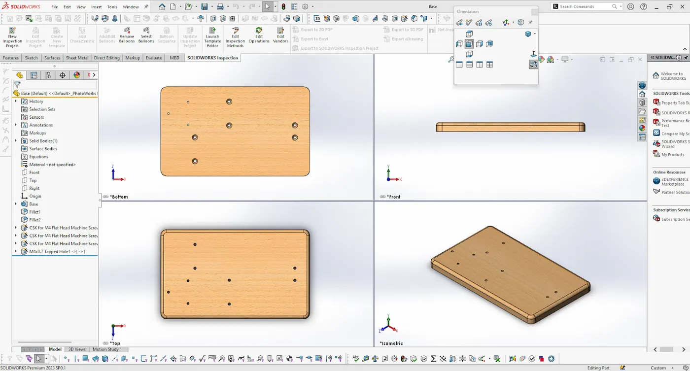
First part of the Stirling engine parts that we're going to make is the base. This would be a wooden or maybe a metal plinth or a base that everything else fits onto. To make the base, let's start a new part, and then start a sketch on the top plane. Let's draw a center rectangle fixed to the origin. It should be 150 millimeters high and 250 long, like this. And then let's just extrude this upwards 15 millimeters using a blind extrude. So this is basically just a short plank of wood that all of the other parts fit on top of. And we can rename that feature as Base. To tidy up a little bit, let's round off the corners, so grab the Fillet tool, and let's set a 10 millimeter fillet around these four outer corners, and then grab the Fillet tool again. And let's round off this top one with a five millimeter fillet. So you can see already just with those rounded corners, it already looks a little bit better. We can also add a wooden appearance, so if you go to the Appearance, Scenes, and Decals tab, which is this little colored ball over here on the right, and then expand Appearances, and Organic, there's loads of different types of wood in here. So you can just choose one of those, and you can double-click to add it to your entire model. So already that looks much better. And that's all there really is to this part at this stage. Later on, we'll add some screw holes to attach the different parts, but we're going to add those from within the assembly. So first we have to build that assembly. So for now, all you have to do is save this part, and let's call it Base.
Tools and features used :
Extrude boss
fillet
Part Image
Flywheel
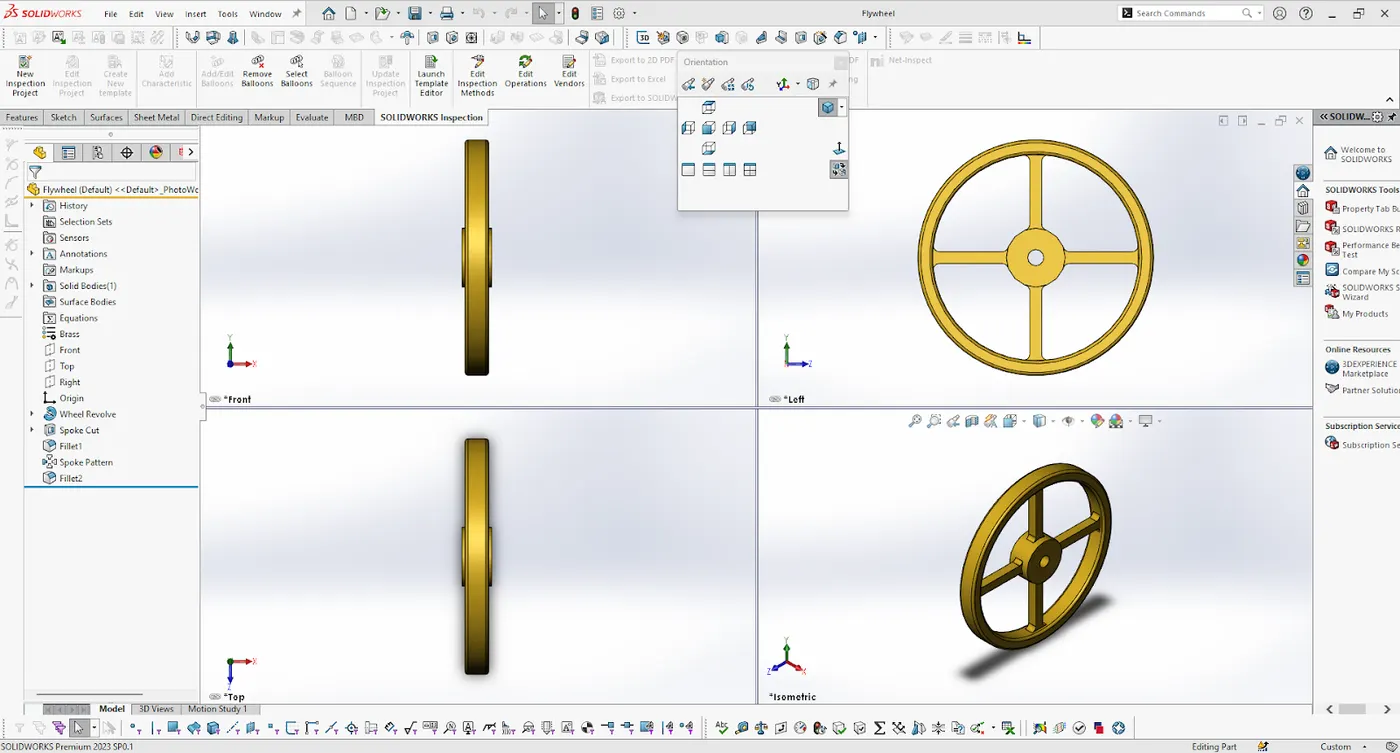
Flywheel is the part of the engine that actually spins round and gives an output.
Tools and features used :
Extrude cut
Revolved
Circular Pattern
Fillet
Part Image
Flywheel Bracket
Tools and features used :
Extruded boss
fillet
Extrude cut
Part Image
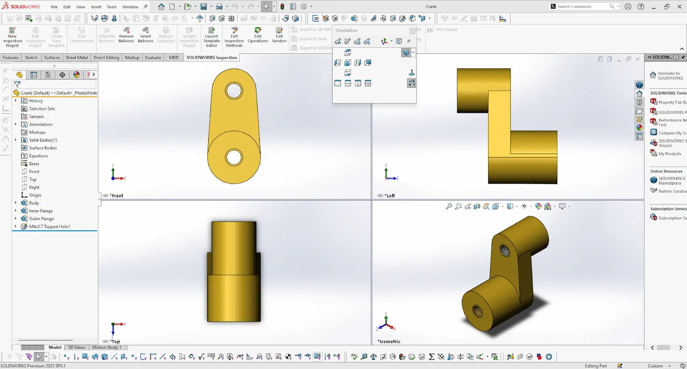
Crank
Tools and features used :
Extrude boss
Part Image
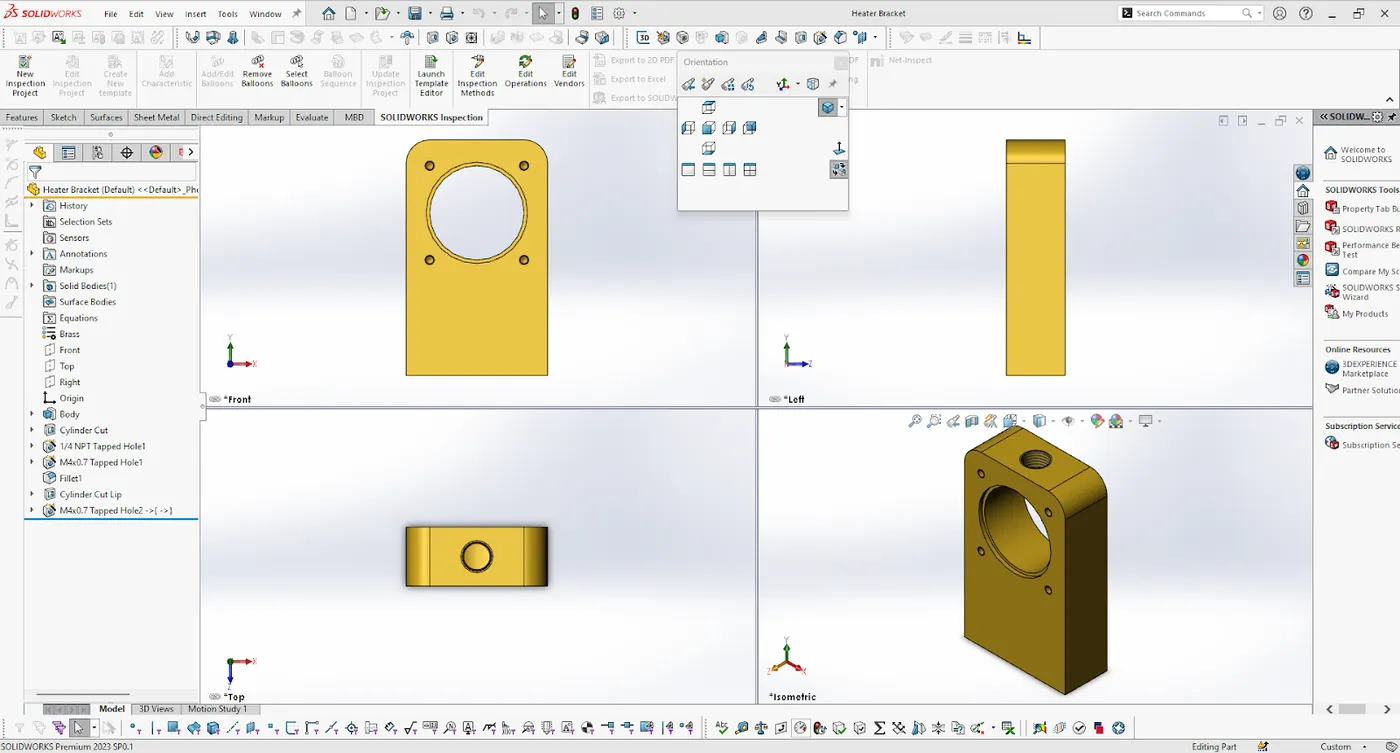
Heater Bracket
Tools and features used :
Extruded boss
Extruded cut
fillet
Part Image
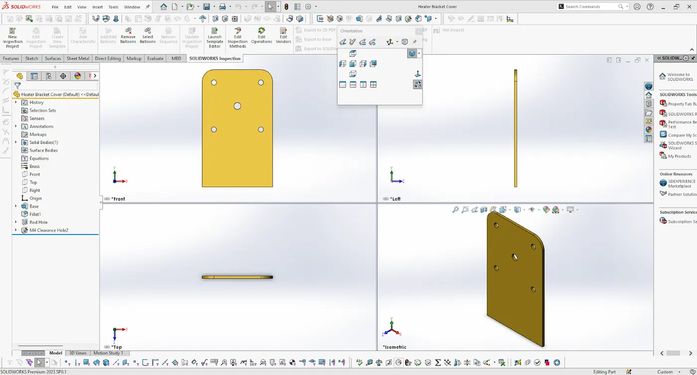
Heater Bracket Cover
Tools and features used :
Extrude cut
Extruded boss
fillet
Part Image
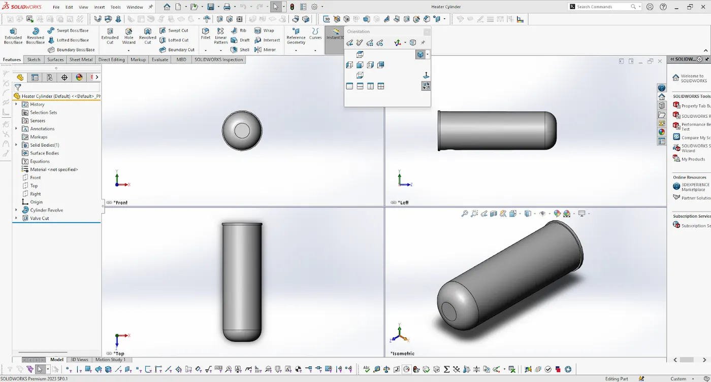
Heater Cylinder
Tools and features used :
Revolved boss
Extruded cut
Part Image
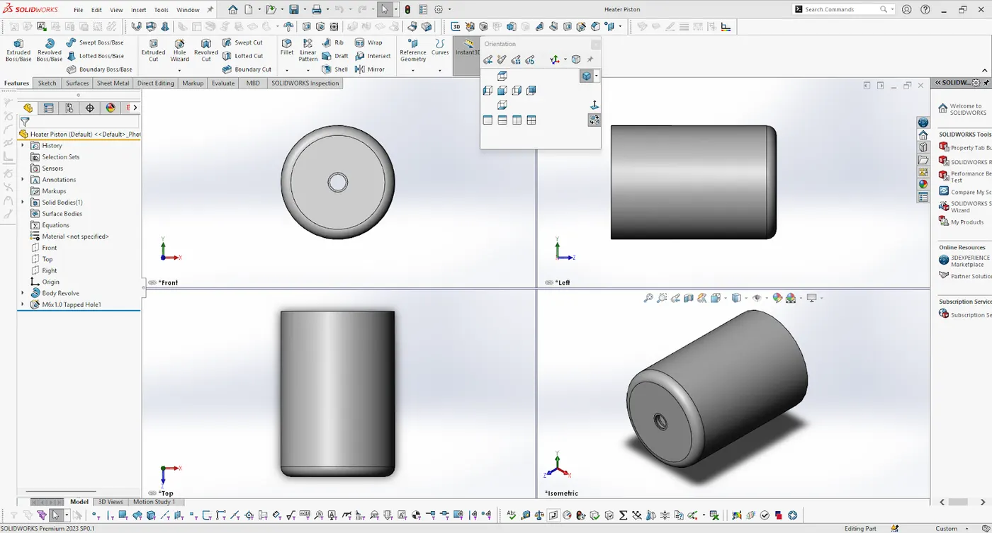
Heater Piston
Tools and features used :
Revolve
Hole
Part Image
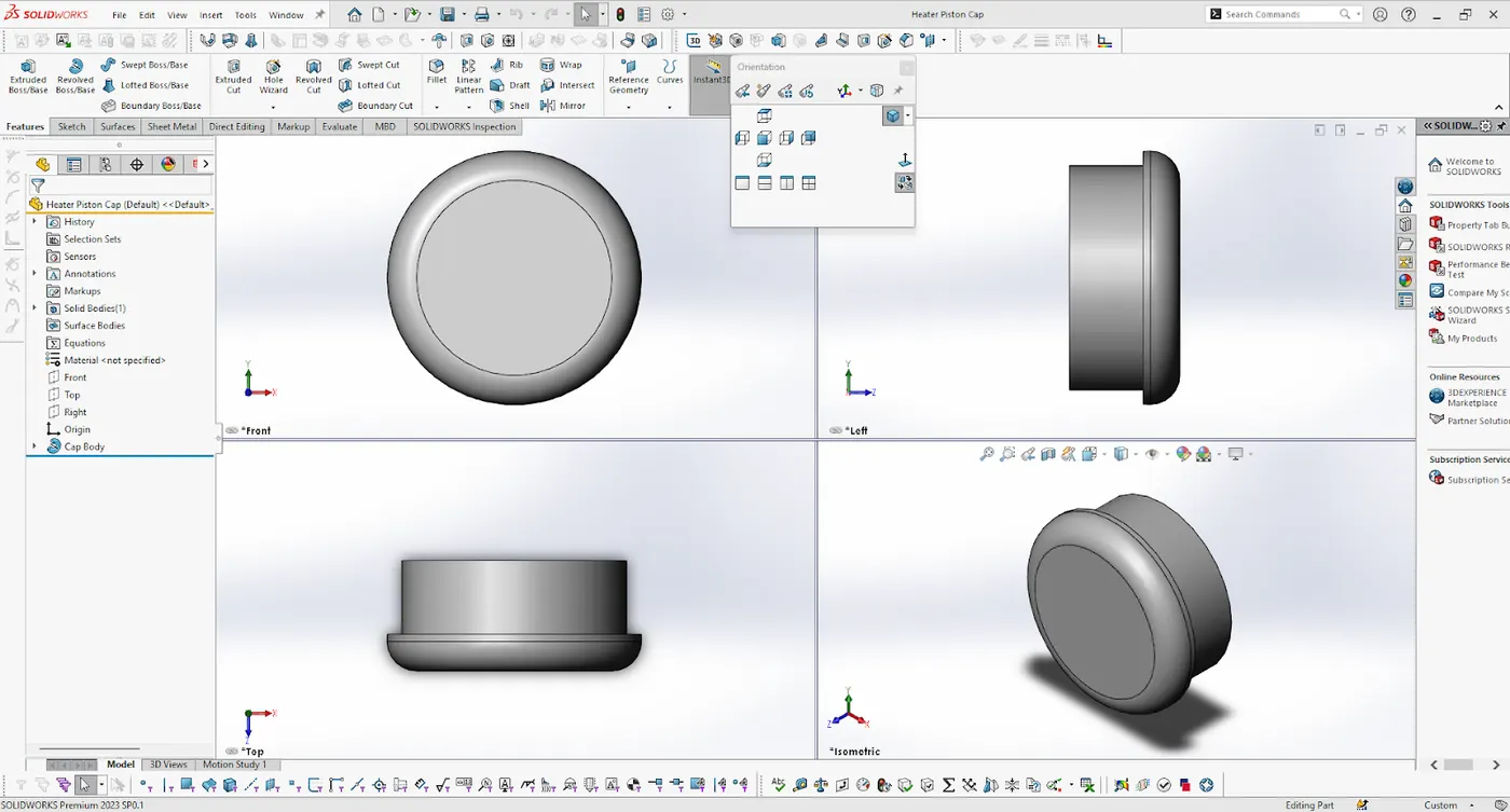
Heater Piston Cap
Tools and features used :
Revolved
Part Image
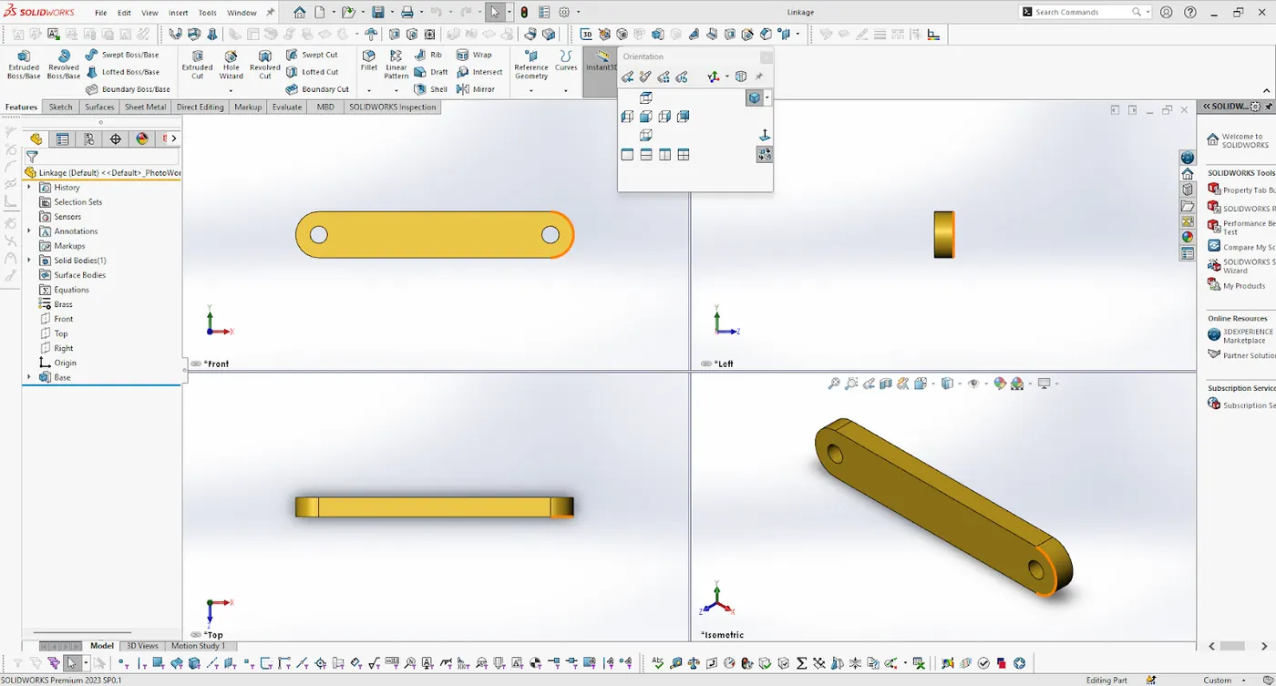
Linkage
Tools and features used :
Extruded boss
Part Image
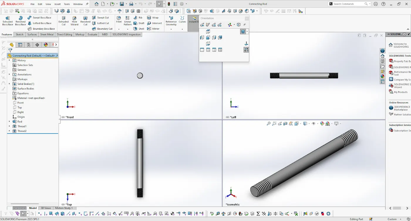
Connecting Rod
Tools and features used :
Extruded boss
Thread
Part Image
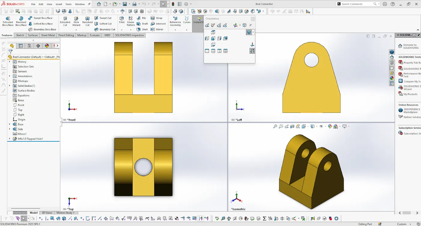
Rod Connector
Tools and features used :
Extruded boss
mirror
Tapped hole
Part Image
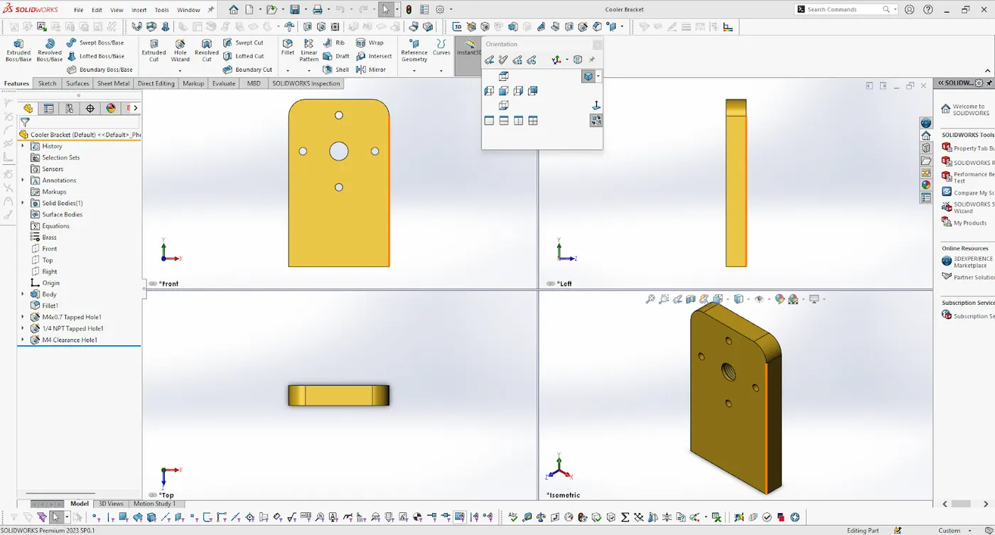
Cooler Bracket
Tools and features used :
Extruded boss
Tapped Hole
fillet
Clearance Hole
Part Image
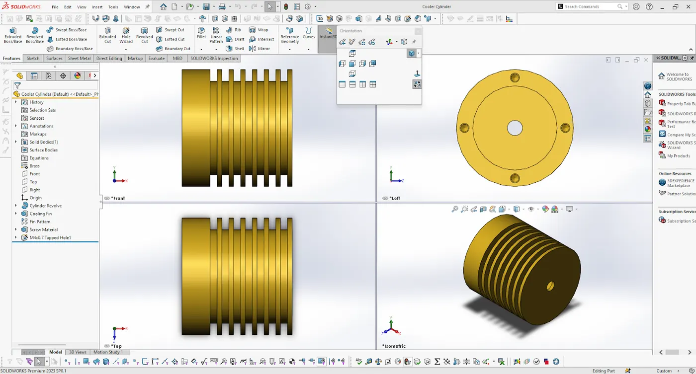
Cooler Cylinder
Tools and features used :
Extruded boss
revolve
Linear pattern
Tapped hole
Part Image
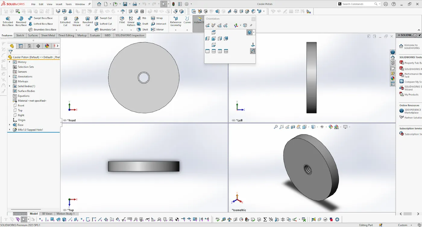
Cooler Piston
Tools and features used :
Extruded boss
Tapped hole
Part Image
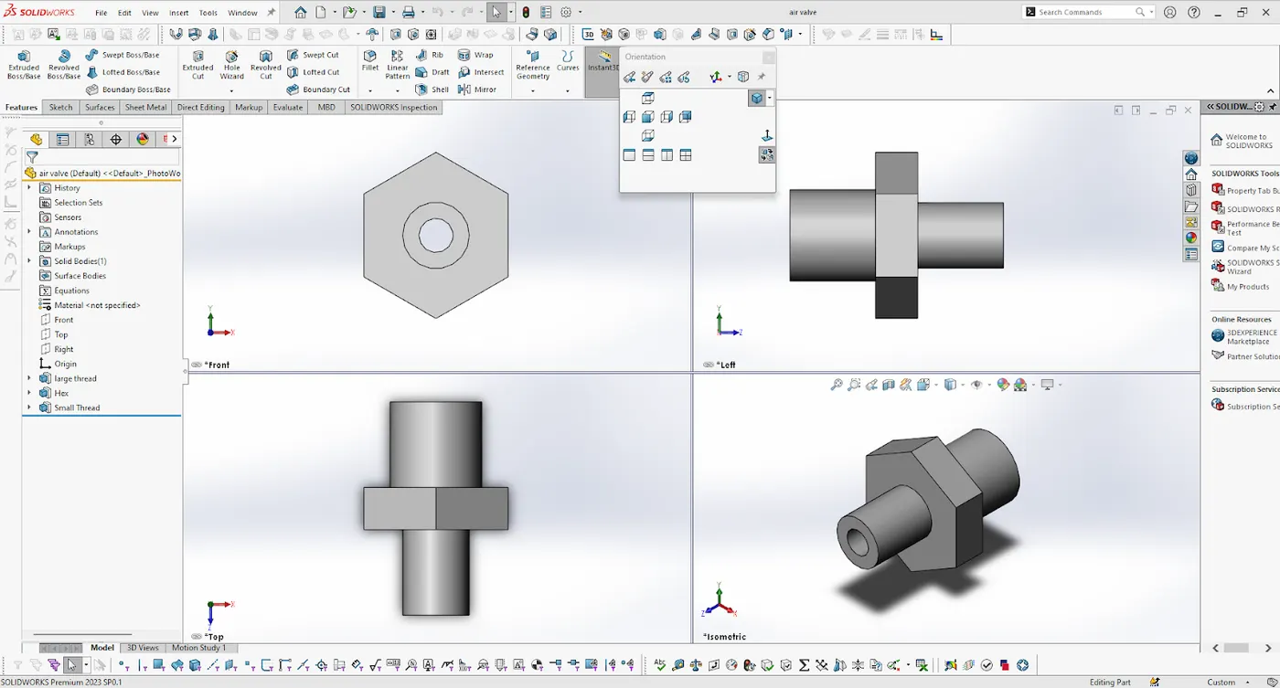
Air valve
Tools and features used :
Extruded boss
Part Image
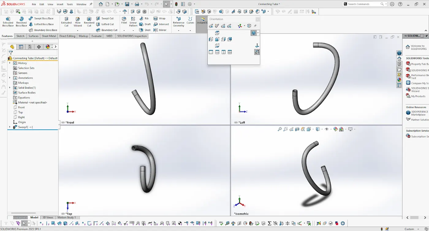
Connecting tube
Tools and features used :
Swept
Part Image
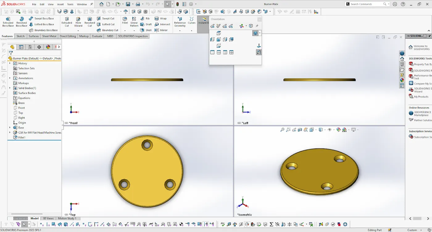
Burner Plate
Tools and features used :
fillet
Extruded boss
Hole
Part Image
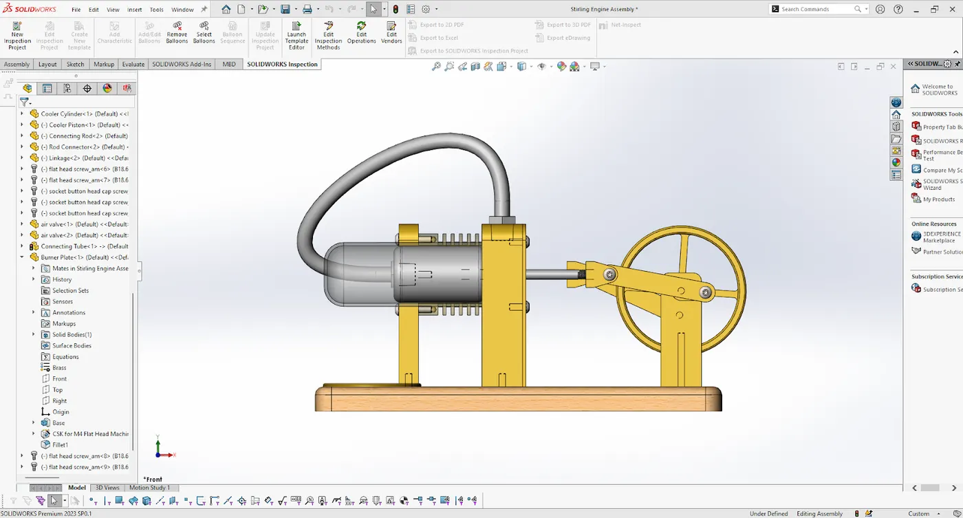
Assembly of the Stirling Engine
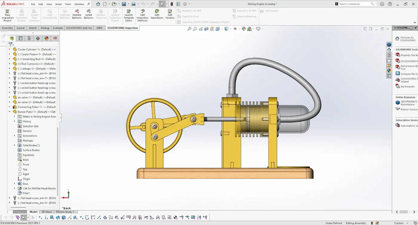
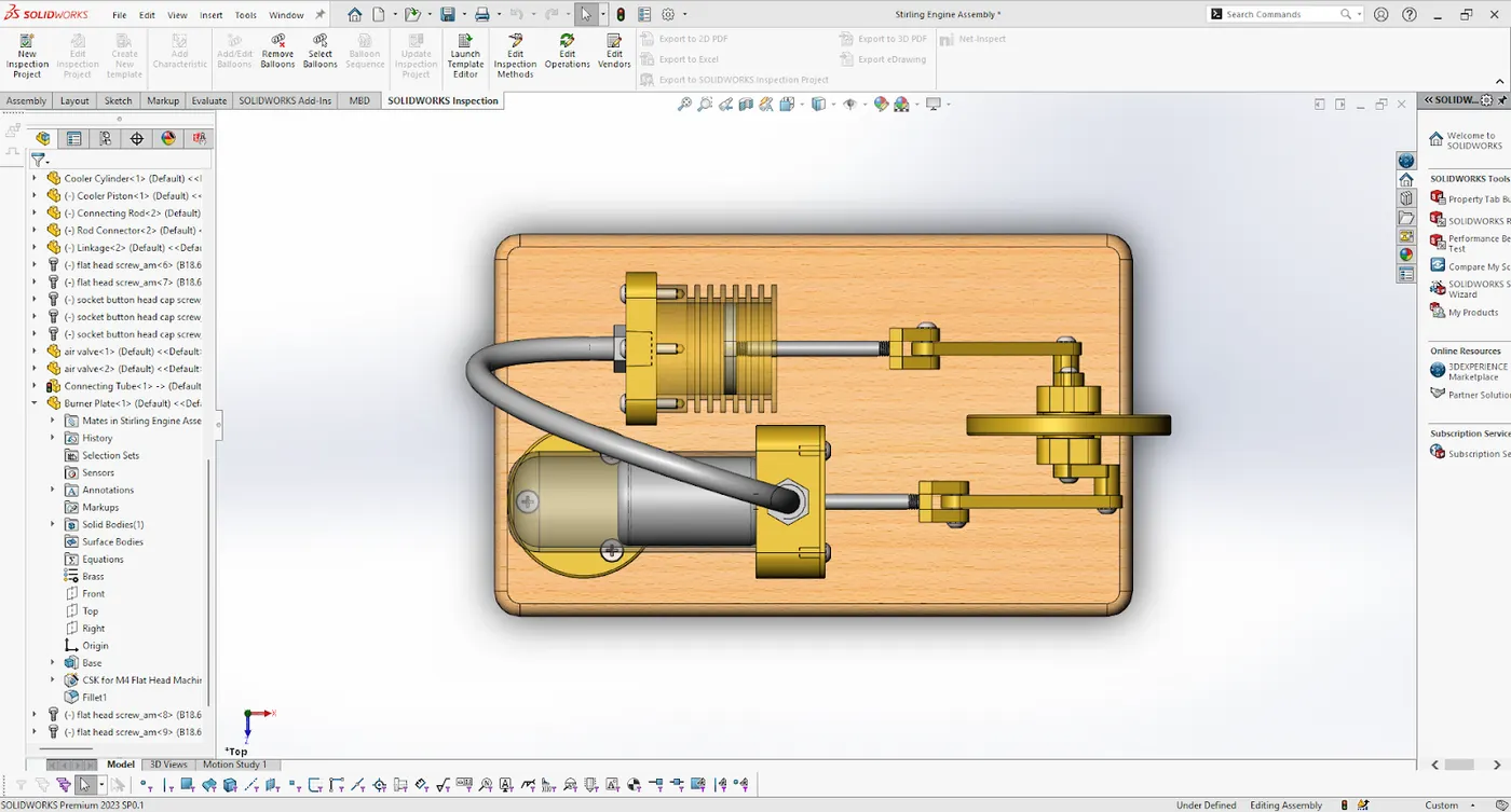
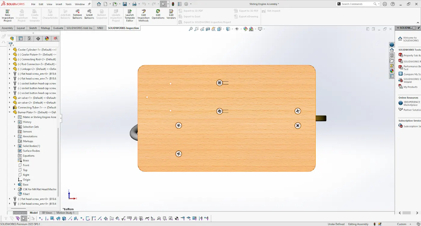
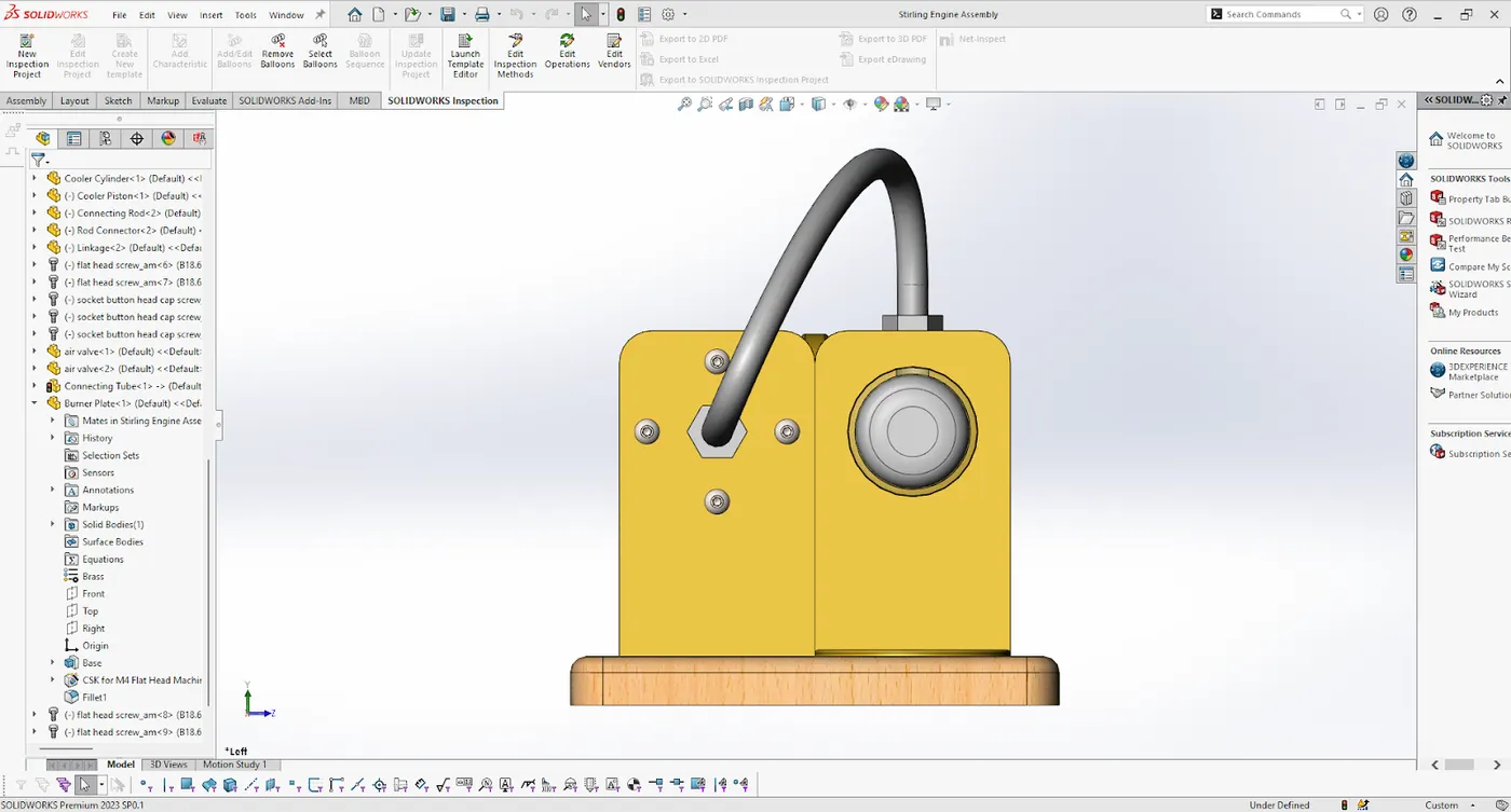
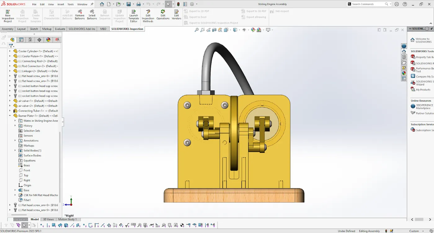
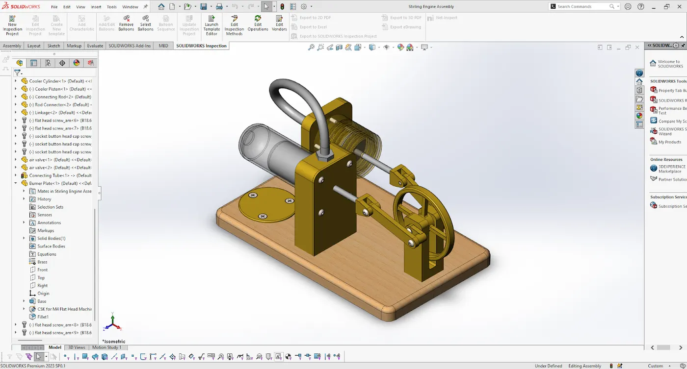
The Stirling Engine is assembled in the solidworks assembly. Various mates are used to construct the Stirling Engine.
Rendering photorealistic image using PhotoView 360:
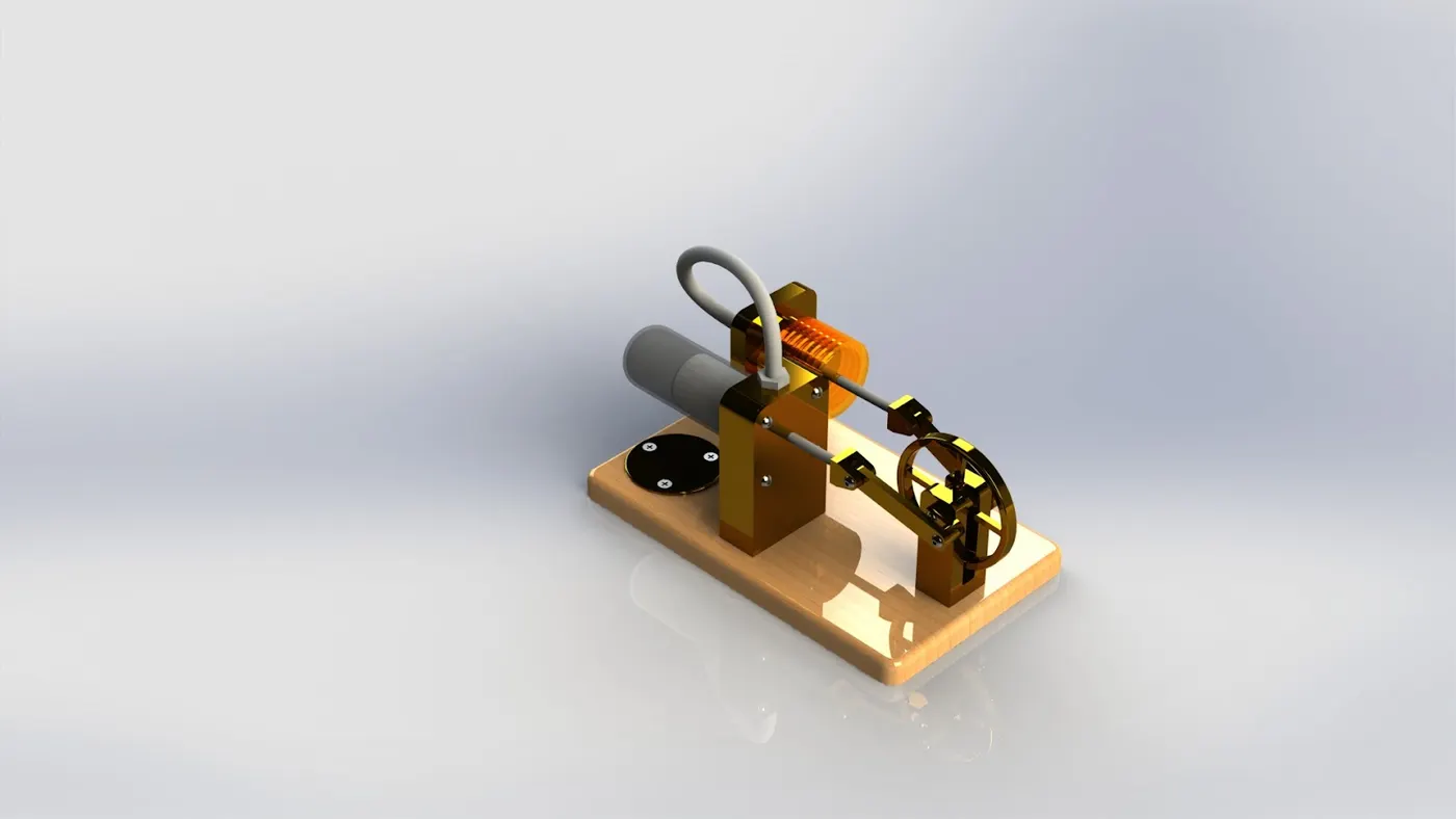
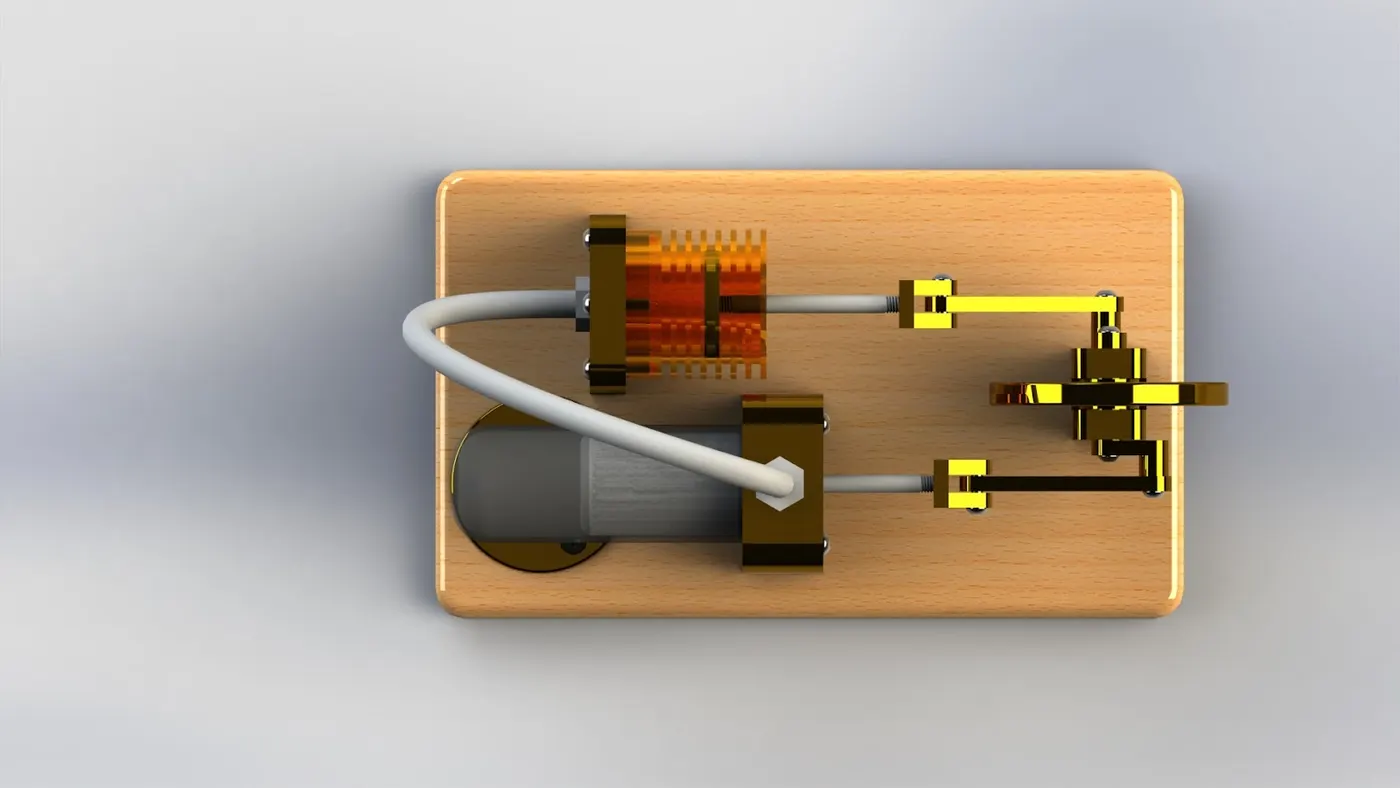
PhotoView 360 is an image rendering software which is available as an add-in in the solidworks.
Conclusion:
All the parts were designed in solidworks
The parts were assembled in the assembly
The assembled Stirling Engine was rendered using Photoview 360