FINAL INDEPENDENT PROJECT
PROJECT REPORT ON 3D MODEL & ASSEMBLY OF “F1 CAR: 2021 CONCEPT”
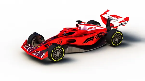
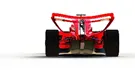
OBJECTIVE: To Design The 3D Model & Assembly Of "F1 Car" Based On 2021 Regulations Proposed By FIA.
INTRODUCTION: Formula one car :-
Formula One (also known as Formula 1 or F1) is the highest class of single-seater auto racing sanctioned by the Fédération Internationale de l'Automobile (FIA) and owned by the Formula One Group.
A Formula One car is a single-seat, open cockpit, open-wheel racing car with substantial front and rear wings, and an engine positioned behind the driver, intended to be used in competition at Formula One racing events. The regulations governing the cars are unique to the championship and specify that cars must be constructed by the racing teams themselves, though the design and manufacture can be outsourced.
FÉDÉRATION INTERNATIONALE DE L'AUTOMOBILE (FIA)

The Fédération Internationale de l'Automobile (FIA; English: International Automobile Federation) is an association established on 20 June 1904 to represent the interests of motoring organisations and motor car users.
The FIA is generally known by its French name or initials, even in non-French-speaking countries, but is occasionally rendered as International Automobile Federation.
Its most prominent role is in the licensing and sanctioning of Formula One, World Rally Championship, World Endurance Championship, World Touring Car Cup, World Rallycross Championship, Formula E and various other forms of racing.
THE KEY CHANGES OF 2021 CONCEPT:-
Despite changes aimed at improving the racing this year, current F1 cars lose 50% of their downforce when running behind another car.
Formula 1 plans to change that with a radical overhaul of car design in two years’ time. F1 motorsport director Ross Brawn has said some of their concepts for 2021 lose about 5-10% of their downforce in the slipstream of another car.
2021 F1 cars will have a radical new design philosophy and striking new look with Sweeping bodywork,
- Simplified front wings,
- Bigger rear wings,
- Increased underbody aerodynamics,
- Wheel wake control devices,
- Simplified suspension and
- Low-profile tyres with 18-inch rims.
BLUEPRINTS THAT I HAVE USED IN THIS MODEL:
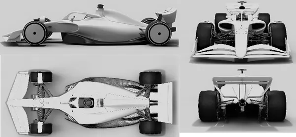
Fig : Reference Images Used To Design The 3d Model
Using this blueprint, I have created a frame over which I have designed my model. The dimensions are taken basically based on assumption but the approximate value is taken about half of its standard dimension i.e.
- 2457*1379 mm for mid plane
- 1256*678.32 mm for front plane
- 1256*678.32 mm for back plane
- 2487*1396 mm for top plane
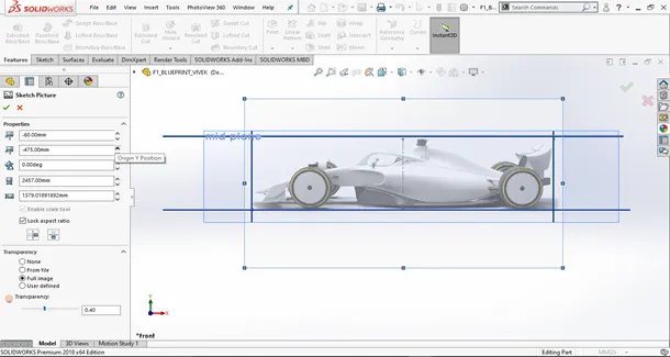
Fig: Blueprint of the side view of f1 car
CHASSIS OF F1 CAR :
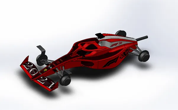
Fig. chassis of f1 car
Chassis is the main body part of the whole model. It consists of the front wing, seat, & exhaust tube at the rear end of it. In this part model, I have used most of the surface modelling features which is mentioned below as:
Curve:- used to create complex shapes of chassis. it is created by the intersection of projecting curves or lines, sketched in a different plane.
3d sketch:- used to sketch in open space.
Surface loft: used to create a surface using 2 guide curves & 2 profile curves.
Surface trim: used to trim the extended surface.
Surface extrude: used to extrude the surface using the sketch entity.
Surface extend: used to extend the surface by selecting the edge.
Surface knit: used to knit the surfaces & combined into a single unit.
Surface fill: used to create the planar surface by selecting the edges to fill surface.
Sweep: used to create a curvy shaped solid part using a profile sketch & profile path.
Chamfer: used to give taper shapes to corner & edges
Fillet: used to give round shapes to corner & edges.
Boss extrude: used to extrude the 2D sketch up to a limited height.
Cut extrude: used to form a hole or cut the extruded part.
Split line: used to split the face on the basis of 2d sketch.
Loft: used to create an irregular-shaped solid part using at least two profile curve & two guide curves.
Split: used to split the solid part from the main body.
Combine: used to combine two or more than two solid parts.
Linear pattern: used to pattern the feature along a linear direction.
Surface thicken: used to thicken the surface.
Dome: used to create the dome shape structure over a planar surface.
Split line: used to split the face on the basis of 2d sketch.
Front wing: In 2021 concept, front wing has a simple design with 3 wing element. At the front, the wing profiles now span the full width of the car, intersecting the nose in the middle, unlike the earlier wings that hang below the nose and have a mandatory neutral centre section. This is a key change and cures some of the problems of 2009 Overtaking Working Group in not being able to follow up on their initial research. The post-2009 front wings created problems for following cars, as they were so wide and had the change in the section from wing to the neutral centre span.
Here are the following commands used in this part:
Surface loft: used to create a surface using 2 guide curves & 2 profile curves.
Surface trim: used to trim the extended surface.
Surface extrude: used to extrude the surface using the sketch entity.
Surface extend: used to extend the surface by selecting the edge.
Surface knit: used to knit the surfaces & combined into a single unit.
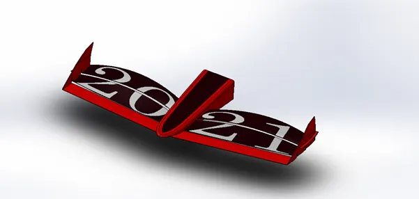
Fig. front wing
LONG FLOOR PLATE(DIFFUSER):
2019 F1 floors feature a step along the centre of the car to lift the diffuser clear of the floor, to reduce its performance and sensitivity. Now, the floor of the monocoque and sidepods are on one plane, still with a plank along the centreline, but with larger tunnels. The most obvious change is the leading edge of the floor featuring a raised venturi inlet with the vanes inside acting as bargeboards to control the airflow through the floor to improve the downforce produced from ground effect.
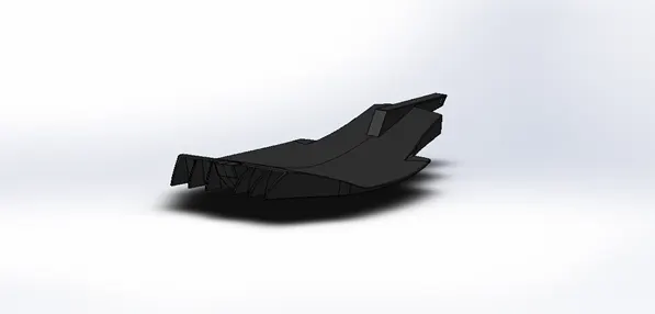
fig: Diffuser
In this part model I have used the following features:
Surface loft: used to create a surface using 2 guide curves & 2 profile curves.
Surface trim: used to trim the extended surface.
Surface extrude: used to extrude the surface using the sketch entity.
Surface extend: used to extend the surface by selecting the edge.
Surface knit: used to knit the surfaces & combined into a single unit.
Boss extrude: used to extrude the 2D sketch up to a limited height.
Cut extrude: used to form a hole or cut the extruded part
Chamfer: used to give taper shapes to corner & edges.
Fillet: used to give round shapes to corner & edges.
Mirror: used to create the half portion of a part on its opposite side by selecting a plane or face as a mirror face.
Linear pattern: used to pattern the feature along a linear direction.
Steering wheel: The steering wheel is used for giving direction to front tyres using the steering wheel mechanism.
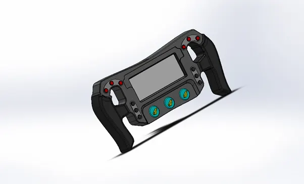
Fig. steering wheel
In this part I have used the following features:
Boss extrude: used to extrude the 2D sketch up to a limited height.
Cut extrude: used to form a hole or cut the extruded part
Chamfer: used to give taper shapes to corner & edges.
Fillet: used to give round shapes to corner & edges.
Mirror: used to create the half portion of a part on its opposite side by selecting a plane or face as a mirror face.
Linear pattern: used to pattern the feature along a linear direction.
Tyre & Wheel: In 2021 concept design, low profile tyre is introduced & wheel dimension is increased from 13 inches to 18 inches by FIA.
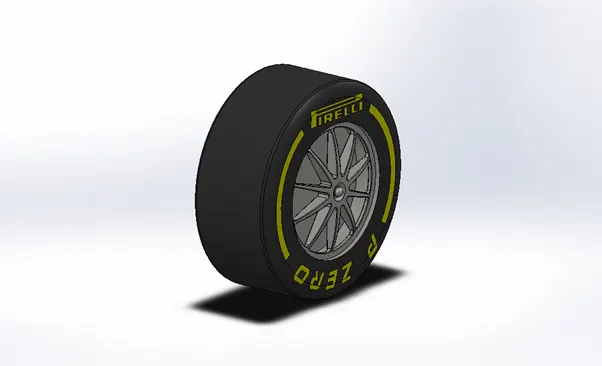
Fig. front tyre
In this part, I have designed the part model using the following features:
Revolve: used to create a revolve shape by giving one of the lines as a central axis about which the sketch is to be revolved.
Cut extrude: used to form a hole or cut the extruded part.
Chamfer: used to give taper shapes to corner & edges
Fillet: used to give round shapes to corner & edges.
Boss extrude: used to extrude the 2D sketch up to a limited height.
Cut extrude: used to form a hole or cut the extruded part.
Split line: used to split the face on the basis of 2d sketch.
REAR WING: according to 2021 regulations, the rear wing is few mm wider than earlier design proposed in 2019. The rear wing is much taller and narrower than current wings while it sees the return of the lower beam wing elements spanning from the rear crash structure across to the wing endplates. This will keep the diffuser tunnels and top rear wing working together, which should make the rear downforce more consistent.
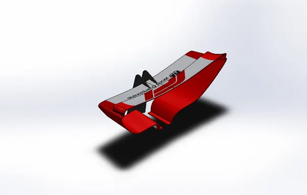
Fig: rear wing
In this part model, I have used the following command features:
Loft: used to create a solid part with an irregular shape.
Cut extrude: used to form a hole or cut the extruded part.
Fillet: used to give round shapes to corner & edges
Boss extrude: used to extrude the 2D sketch up to a limited height.
Mirror: used to create the half portion of a part on its opposite side by selecting a plane or face as a mirror face.
Combine: used to combine two solid part together.
Assembly of f1 car: 2021 concept:-
After completing all the part model of f1 car, I have combined all the parts in a single using various mates. The mates which are used in it are as follows:-
Coincident mate: used to coincident the parts via their opposite faces.
Concentric mate: used to aline the parts along a single plane or direction.
Parallel mate: used to place the parts parallelly, by selecting their same side face.
Limit angle mate: used to limit the angle of rotation of parts. etc.
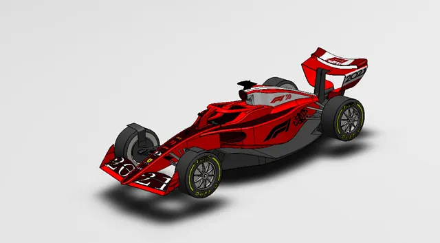
Fig : Assembly of f1 car
RENDERING OF ‘F1 CAR : 2021 CONCEPT:
The rendering is done using photoview 360, which gives an aesthetic look to the ‘F1 car’. The following steps are taken to render the F1 car assembly:
- At first switch on the photoview 360 option,
Tools -> add-in-> photoview 360
- Then go to render tool option. In this section, all option is available to set the rendering.
- Set Chopper assembly in a perspective view.
- Add the camera to set up the view at an angle.
- Add lights, to get appropriate brightness over the assembly.
- Add background scene & environment scene to give the assembly an outstanding background.
- Click on an option from render tool, toolbar to set the size of the window.
- Then, the Preview window option is used to create a preview image of the setup.
- & after that final render is done using final render option given in render tool, toolbar.
- After getting a desirable look to the assembly, click on save image option to save the image.
RENDERING IMAGES OF F1 CAR: 2021 CONCEPT:-
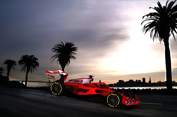
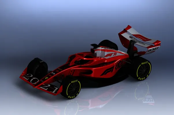
Here are some rendered images, which I have created using ‘Photoview 360’:
ALL VIEWS OF F1 CAR :
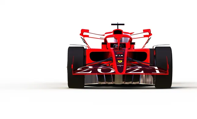
FIG. FRONT VIEW
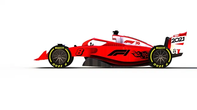
FIG. SIDE VIEW
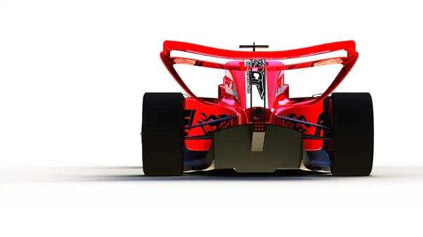
FIG. BACK VIEW
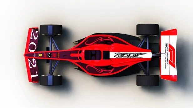
FIG. TOP VIEW
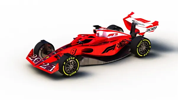
FIG. CAMERA SETUP VIEW
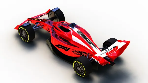
FIG. ISOMETRIC VIEW
SOME OF THE RENDER IMAGES USING IMAGE BACKGROUND:
- Here is All view of my design of F1 car in blue colour:
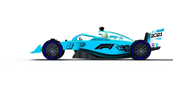
Fig. side view
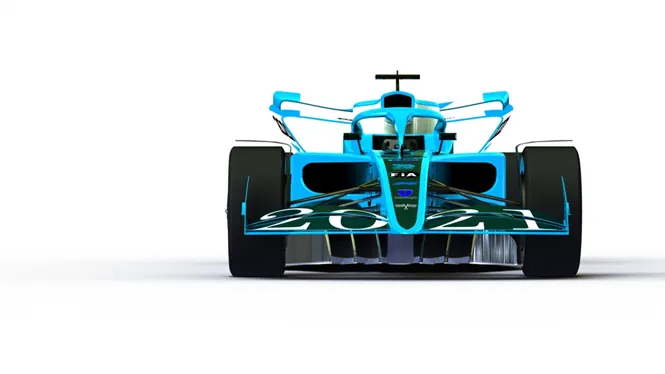
Fig. Front view
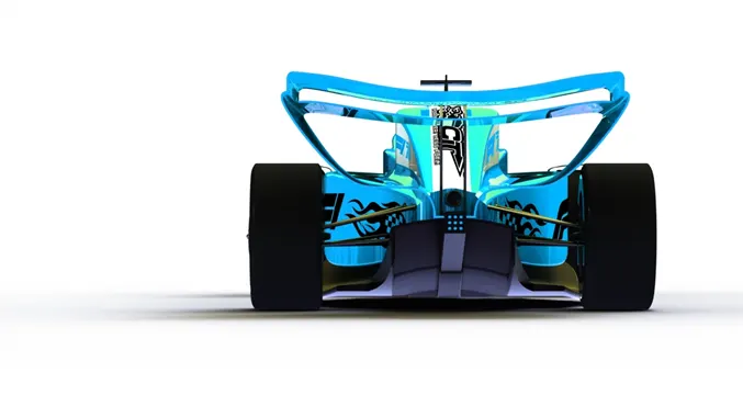
Fig. Back View
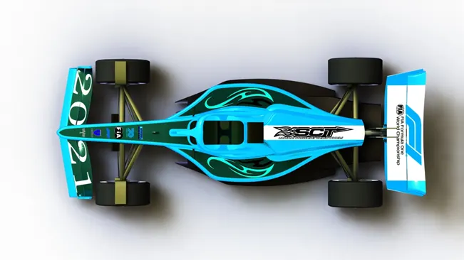
Fig. Top View
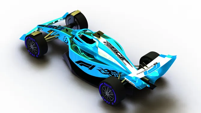
Fig. Isometric view
CONCLUSION:-
Through this project, I have learnt about the solid & surface modelling features of Solidworks. This project is basically based on surface modelling but I have used some solid modelling feature also. I have also learnt to do the rendering of assembly using photoview 360 software. Photoview 360 software helps me creating an aesthetic look.
HERE IS THE GOOGLE DRIVE LINK FOR ZIP FILE OF SOLID PART MODEL & ASSEMBLY OF " F1 CAR: 2021 CONCEPT"
https://drive.google.com/file/d/1xG8flCPDIx8MtWYfnZQeuUGDhpazl0t-/view?usp=sharing
HERE IS THE GOOGLE DRIVE LINK FOR PPT ON MODEL & ASSEMBLY OF " F1 CAR: 2021 CONCEPT"
https://drive.google.com/file/d/1ZDgQMGefdC1m0FwedQcorQ350jL_QYDb/view?usp=sharing
REFERENCES
- https://www.racecar-engineering.com/articles/f1-2021/
- https://www.formula1.com/en/latest/article.2021-f1-rules-the-proposed-blueprint-for-racings-future
- https://www.turbosquid.com/3d-models/formula-1-season-2021-3d-model-1491340
- https://www.racefans.net/2019/04/02/how-will-f1-revolutionise-the-racing-in-2021-its-new-concept-car-analysed/
- https://motorsport.tech/formula-1/f1-2021-regulations-overview-by-craig-scarborough
- https://freebiesupply.com/logos/fia-logo-3/
- https://formulaspy.com/f1/formula-1-reveals-special-logos-for-2020-66884
- https://www.autosport.com/f1/news/133289/formula-1-unveils-new-logo
- https://rmtyresltd.co.uk/rm-tyres-strood-ltd/pirelli-logo-2/
- https://www.nicepng.com/ourpic/u2w7u2o0y3t4e6y3_sct-performance-parts-st-louis-sct-performance-logo/
- https://www.redbubble.com/shop/motorsport+stickers
- https://www.tenstickers.co.za/stickers/race-car-with-stripes-white-and-red-car-decal-A18562
- https://grabcad.com/library/formula-1-car-concept-2021-1
- https://www.turbosquid.com/3d-models/f1-wheel-steering-3d-model-1413171