FINAL INDEPENDENT PROJECT
WHEEL LOADER
OBJECTIVE :
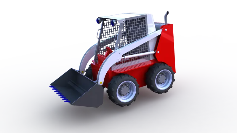
Design,Assembly and Rendering of a Sand Loader Using Solidworks and Solidworks Visualise.
INTRODUCTION :
WHEEL LOADER ;
Wheel loaders are finding great demand due to the increasing focus on road construction and mining.Going forward ,the growth momentum due to increased construction activities of smart Cities- infrastructure development. Wheel loaders are also Demanded in certain applications ,like iron ore mining and bulk handling at ports.It is being -used to load and carry materials Across a job site.Additionally it can haul fine materials like Sand or large objects like rock and demolition debris.
The manufactures of wheel loaders are offering models with variable bucket capacities with with attachment loader buckets, forks , material handling arms grapples, and log pushers. The latest modelsare being upgrated with high torque, so that they can be utilised for for heavy - load operation .Buckets are also designed and shaped for efficient scooping and loading. Newer Models also boast of the new fuel-efficient CEV stage four. Manufacturers are also also placing increased importance on the use of rugged components .
SOLIDWORKS :
- The SOLIDWORKS CAD software is a mechanical design automation application that lets designers quickly sketch out ideas,experiment with features and dimensions ,and produce models and detailed drawings.
- This document discusses concepts and terminlogy used throughtout the SOLIDWORKS application. It familiarizes you with the commonly used functions of SOLIDWORKS.
FEATURES OF SOLIDWORKS USED IN THIS PROJECT :
;
- Line
- circle
- Sketch picture
- 3-point Arc
- Center point Arc
- Corner Rectangle
- Center Rectangle
- Polygon
- spline
- Fillet
- Mirror
- Linear sketch pattern
- Circular sketch pattern
- Offset Entities
- Convert Entities
- Dimension
SOLID MODELLING TOOLS ;
- Boss Extrude
- Cut Extrude
- Revolve Boss
- Sweep Boss
- Extruded Cut
- Fillet
- Chamfer
- Linear Pattern
- Circular pattern
- Fillet
- Reference Plane
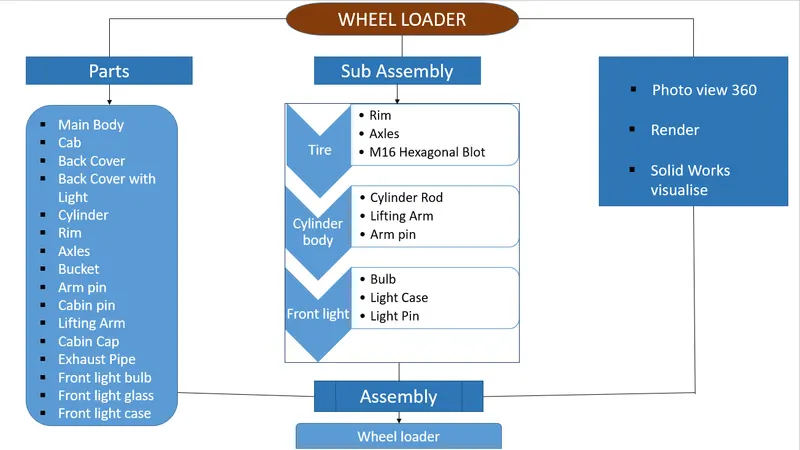
FLOW CHART ;
WHEEL LOADER PARTS ;
1.MAIN BODY :
The Engine of Wheel Loader is inside this main body .The transmission on a wheel loader utilizes the principles of gear ratios to allow the machine to perform at various speeds and at different levels of torque as power is transferred from the engine, through the transmission ,and eventually to the wheels.while a 4-speed transmission is common ,other variations allow for customization for working conditions like when long,repetitive travelling is required.
2. CAB :
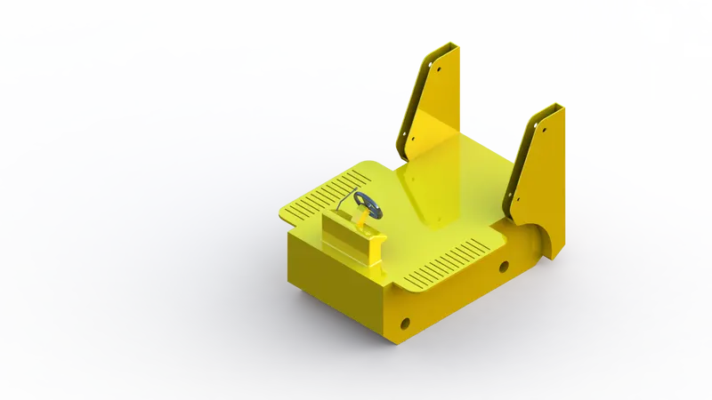
The cab on a wheel loader operates as a central command station for a wheel loader.Due to the Environments they work in,the cabs on wheel loaders are often reinforced with safety equipment and, in designing the cab and how it is incorporated into the machune, a focus is placed on ensuring an operator has clear lines of sight and unobstructed views whlie operating the machine.
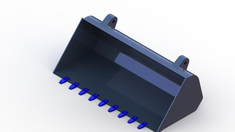
3.BUCKET :
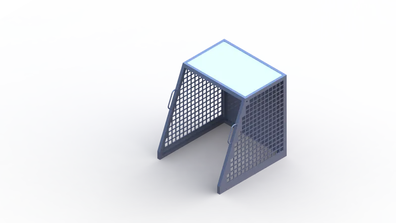
Buckets are the most common type of attachment on wheel loader ,but even buckets come in wide range of sizes and designs to accommodate different materials and different working conditions.from rock buckets in mining to grapple buckets in forestry, a wheel loader can operate as a multi-purpose workhorse with a quick change of the bucket.beyond buckets,forks and plows are common attachments for wheel loaders.
4.LIFTING ARM :
The Lifting arm connects the wheel loader's bucket to the main body of the wheel loader .The lifting arm must be built to accommodate heavy loads,resistance during pushes,and constant and repetitive use .The lenth of the lifting arm defines the reach of the wheel loader and the dumping height of the bucket. A lifting arm that is too short can create issues in loading large equipment or pilling materials above a certain height.

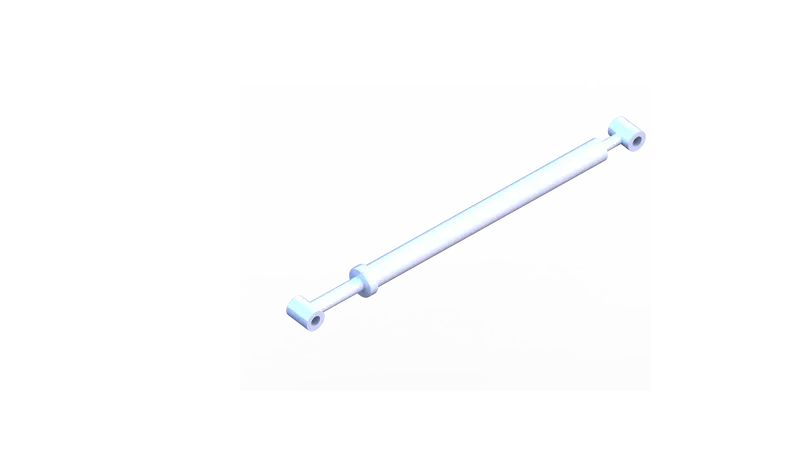
5.CYLINDERS :
Two hydraulic cyclinders,one on each side of the boom, control the lifting and lowering of the boom.These cylinders must be sufficiently powerful to lift heavy loads and designed for frequent use. A wheel loader operator must take care to prevent damage to lifting arm cyclinders during lifts and when the boom is subject to forces from the side.
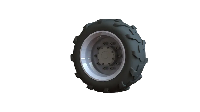
6.RIMS AND TIRES :
Wheel loaders operate in a wide range of ground conditions and,as such,must be designed to accommodate the specifies of the work surfaces.Substantial rims must be designed to hold the considerable weight of many wheel loaders along with the weight of loads they are carrying. Tires must be designed to provide traction in non-paved environments, avoid damage from rough materials,and even prevent over -impacting or harsly compacting surfaces areas.
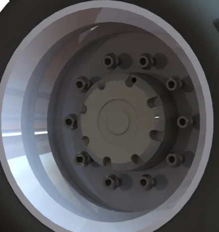
7.Axles :
A substantial front and rear axle on the wheel loader connect the drive systems of the wheel loader to the wheels .since a wheel loader can experience heavy impacts from below,axle shafts and internal gears inside the axle require an especially tough and robust axle housing.
RENDER :
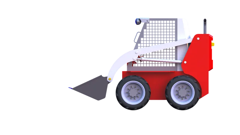
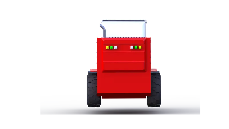
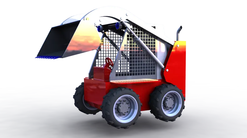
CONCLUSION :
All the parts designed in Solidworks. The Wheel loader was rendered using Photoview 360 as well as Solidworks visualise.