FINAL INDEPENDENT PROJECT
Answer:-
Design, Assembly and Rendering of Circular Loom Machine using SolidWorks and SolidWorks Visualize
Objective:-
- Design the parts of the Circular Loom Machine
- Assembled the parts in solidworks assembly.
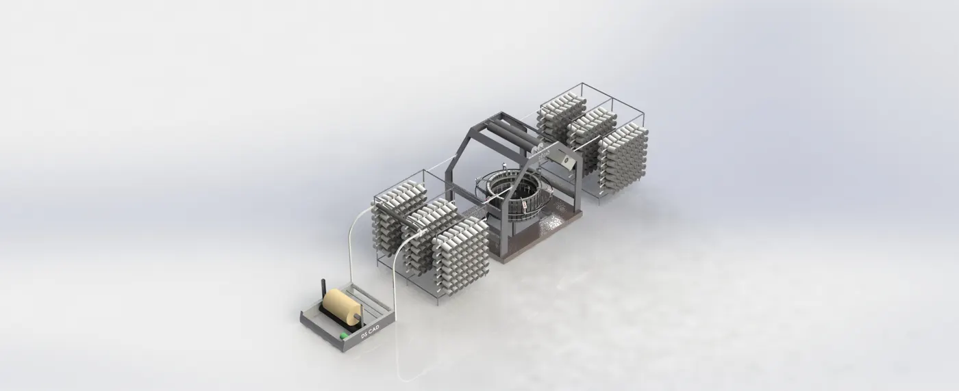
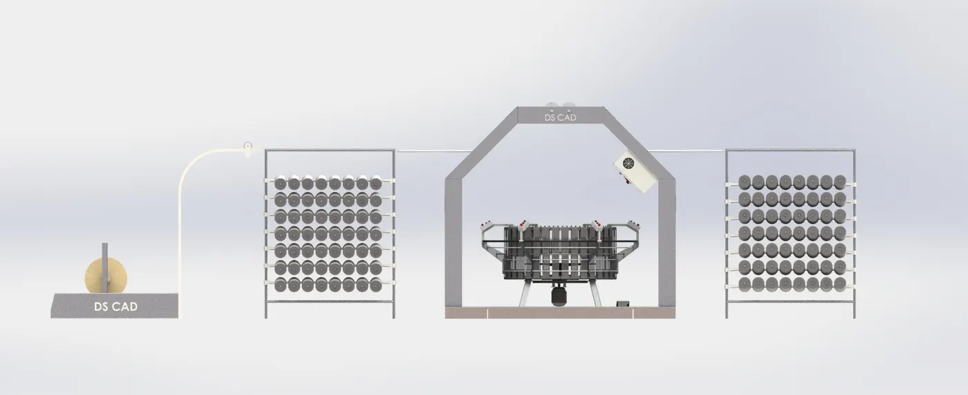
- Rendering image using photoview 360 and SolidWorks Visualize.
Link of Parts & Assembles -
https://drive.google.com/drive/folders/1HLHXGXXHmPtvlKT5RnSF5R76lDleM3Va?usp=drive_link
Software Used:-
SolidWorks 2020
- SolidWorks is a parametric modeling software used for making/Designing models in industries such as automobile, aerospace, etc. The software is parametric, which means the model can be altered or modified at any given time. The design of the model changes with the alterations made in the part while modeling.
Motivation for the Project:-
- I was fond of design since childhood. Earlier I used to work in automobile industries,
Currently I am working in a company which manufactures circular loom machines & other accessories.
From which cloth is made.
Now that I have enough knowledge about it, I thought of making a circular loom machine.
Tools and features used :-
- Sketch
- Extruded boss
- Revolved
- Revolved cut
- Swept boss
- Extrude cut
- Hole wizard
- Swept cut
- Fillet
- Chamfer
- Linear patten
- circular patten
- mirror
- dome
- 3Dsketch
- Base Flange
- Edge Flange
- Combine
- Thread
- Tab
- Vent
- Surface Offset
- Weldment
- Projective curve
- Appearances i.e.
Part Modeled :-
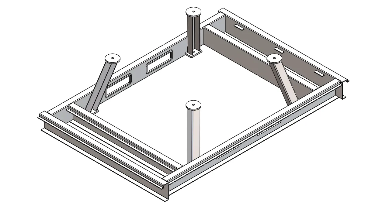
Main Base Frame-
It is the base of the circular machine, on which the weight of the entire machine rests.
which is part of sheet metal.
Tools and features used-
- Base Flange
- Edge Flange
- Extruded Boss/Base
- Extruded Cut
- Mirror
- Fillet
- Combine
Part Image-
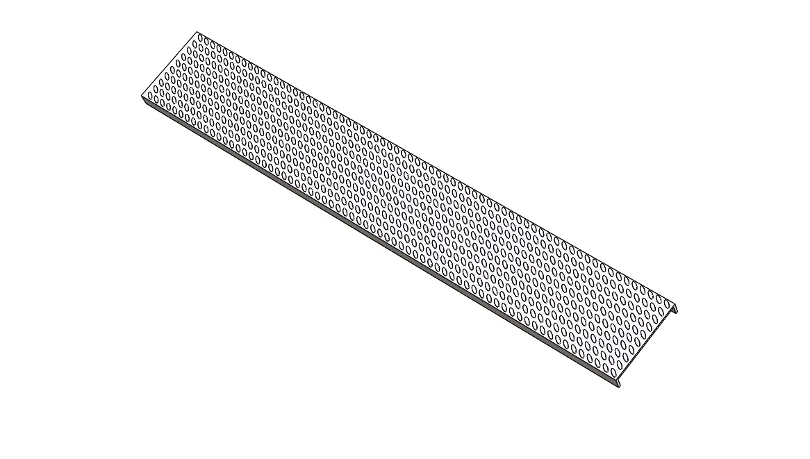
Main Base cover-
This is the cover of the main base frame,
which is made by sheet metal
Tools and features used-
- Extruded Boss/Base
- Body Move/Copy
Part Image-
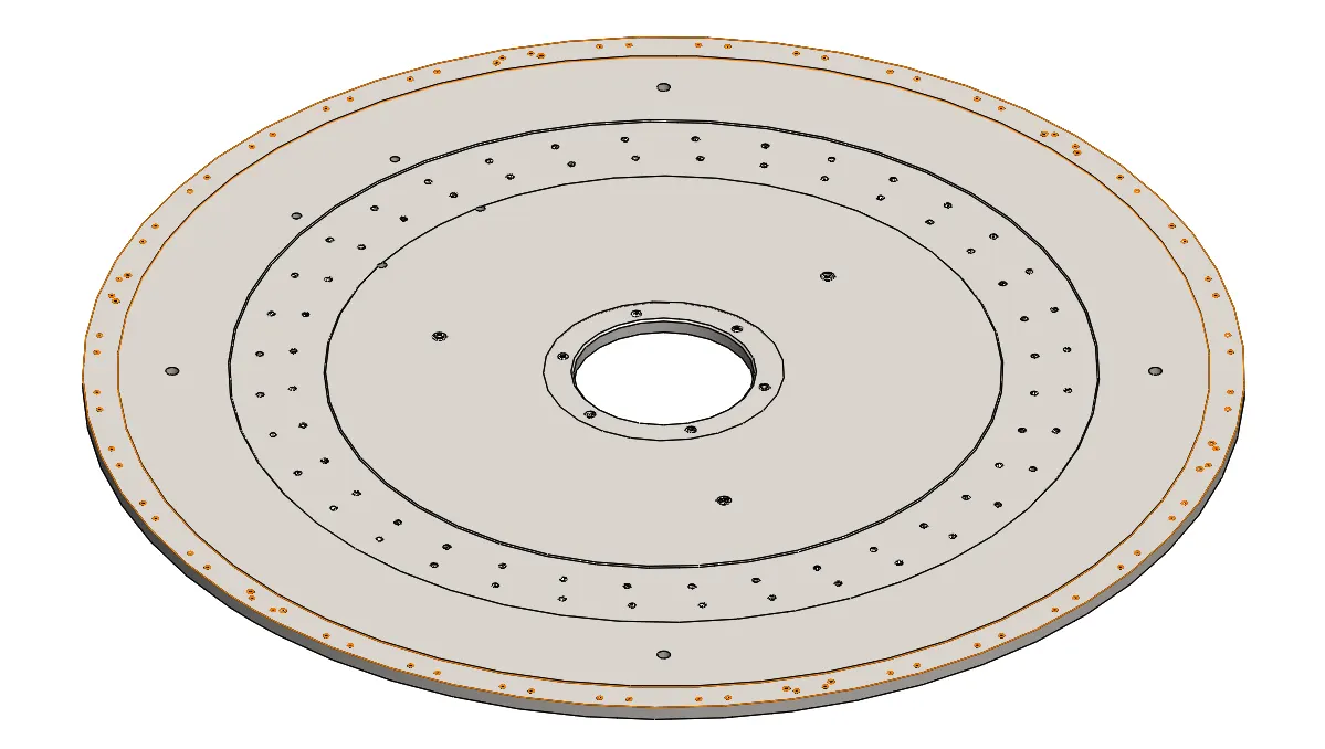
Base Plate-
It is made by solid thick plate,
which is tightened by putting on maggi pads, Under which the motor assembly is assembled.
Tools and features used-
- Extruded Boss/Base
- Extruded cut
- Thread
- Circular Pattern
- Chamfer
Part Image-
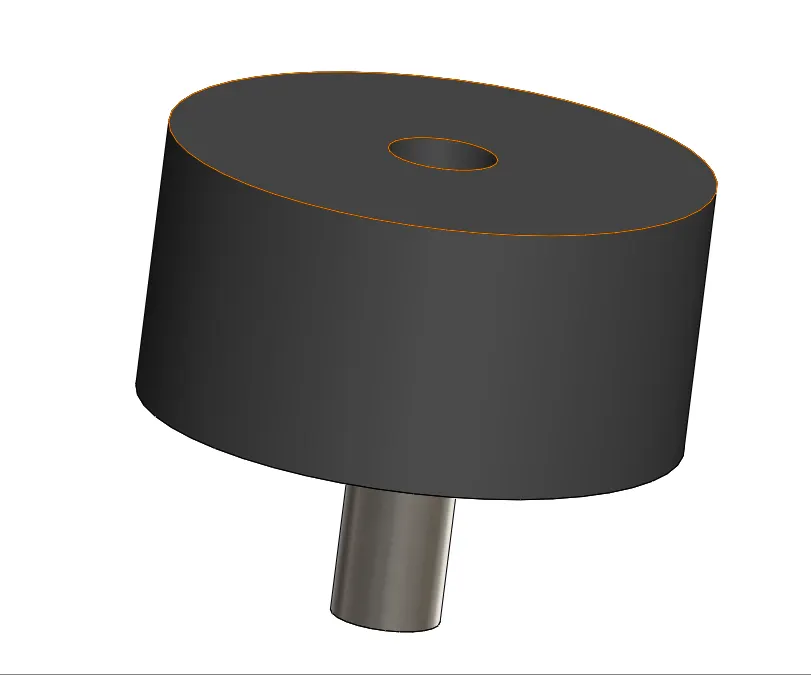
Meggi Pad-
Maggi pad is made of rubber. Which is mounted on the leg of the base frame, which absorbs the vibration of the machine.
and a base plate is placed on top of it
Tools and features used-
- Extruded Boss/Base
- Extruded cut
- Body Move/Copy
Part Image-
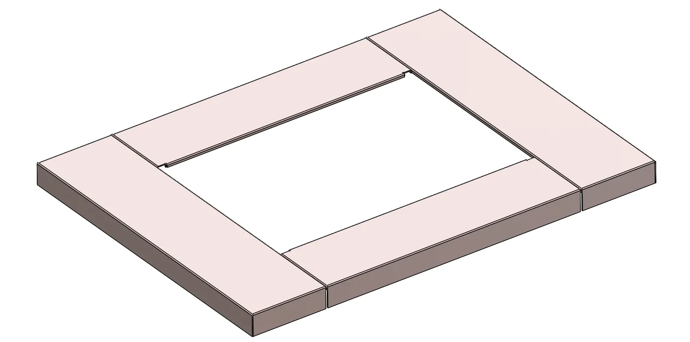
Foot Board-
A narrow platform on which one's feet can stand. and operate the machine.
This is sheet metal parts.
Tools and features used-
- Base flange
- Edge flange
- Tab
- Mirror
Part Image-
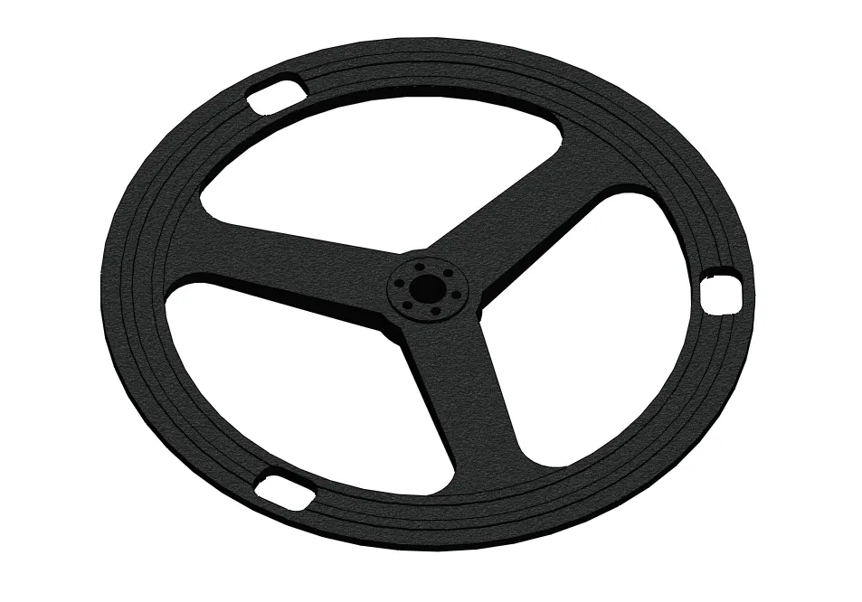
Cam-
It is the made by cast iron metarial. Which is mounted on the adapter and is rotated by the motor.
by which the shuttle on the machine is rotated and from which thread is woven
Tools and features used-
- Revolved Boss/base
- Extruded boss/base
- Extruded cut
- Circular pattern
- Fillets
Part Image-
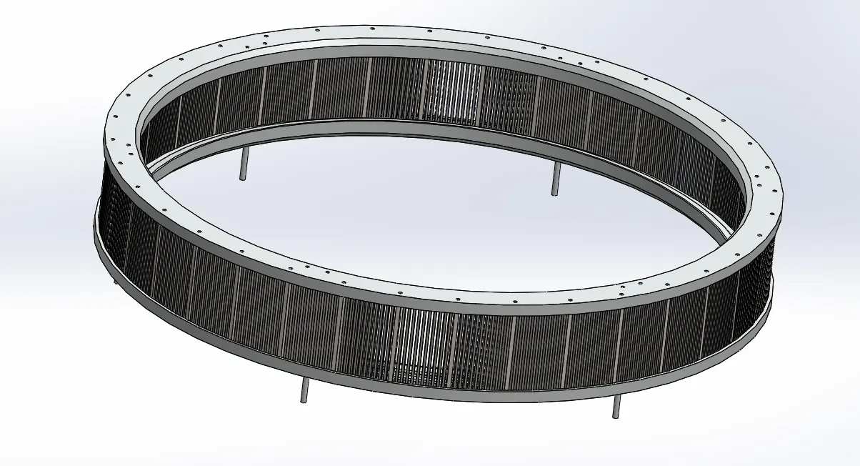
Reed-Ring-
It is the made by cast iron and stainless steel metarial. Which is mounted on the Ring Stand and in which the shuttle rotates.
Tools and features used-
- Revolved Boss/base
- Extruded boss/base
- Extruded cut
- Circular pattern
- Mirror
Part Image-
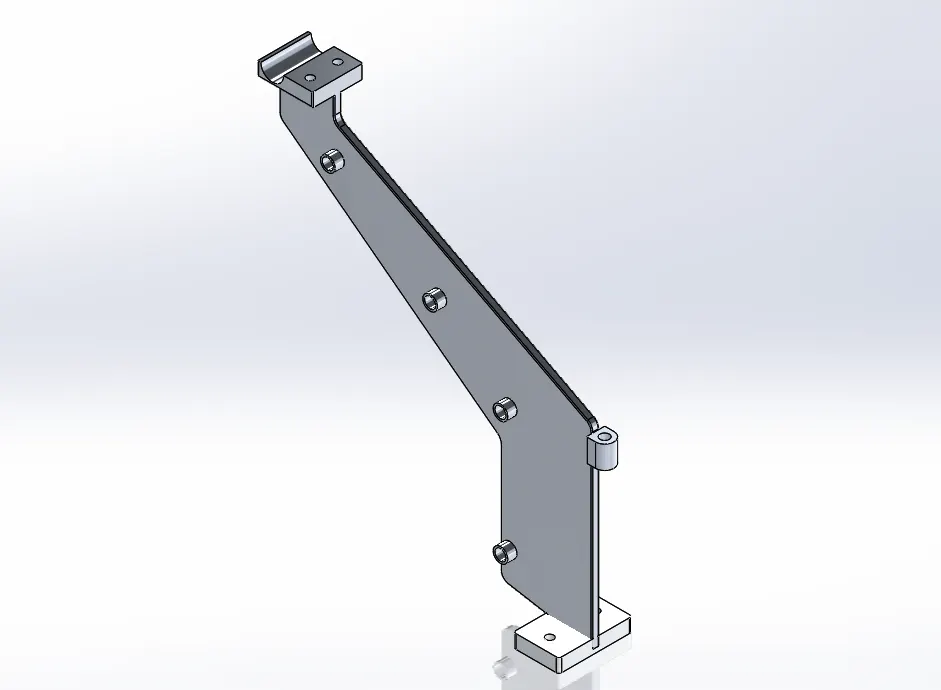
Ring-Stand-
It is the made by Aluminium and it is mounted on the base plate, on which readring are placed.
and supports & gide E-ring
Tools and features used-
- Extruded boss/base
- Extruded cut
- Fillets
Part Image-
Main Adopter-
This is the main adapter assembly with the shaft. Which is mounted on the base plate.
Tools and features used-
- Extruded boss/base
- Extruded cut
- Revolved Boss/base
Part Image-
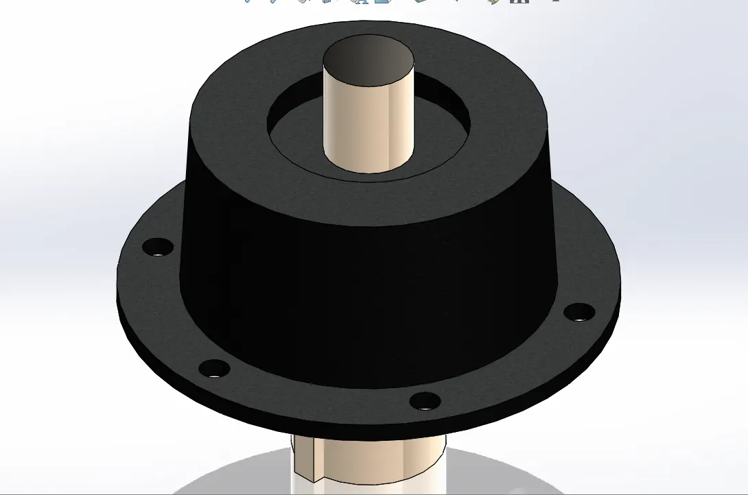
E-ring-
This is an E-ring. In which the wire is hidden, due to which electricity is supplied to all the switch boxes.
Tools and features used-
- Sweep Boss/base
Part Image-
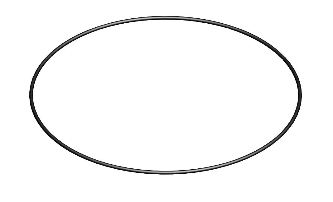
Segment-
This is a casting of the block which is mounted on the reading,
on which the upper bearing block is mounted
Tools and features used-
- Extruded boss/base
- Extruded cut
Part Image-
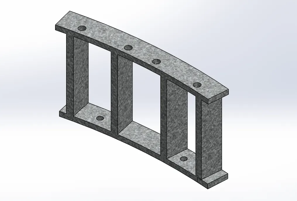
Upper Bearing Block-
This is an upper bearing block, which is part of sheet metal.
Which is mounted on the segment.
In which the deflecting pulley is assembled
Tools and features used-
- Extruded boss/base
- Extruded cut
- Fillets
Part Image-
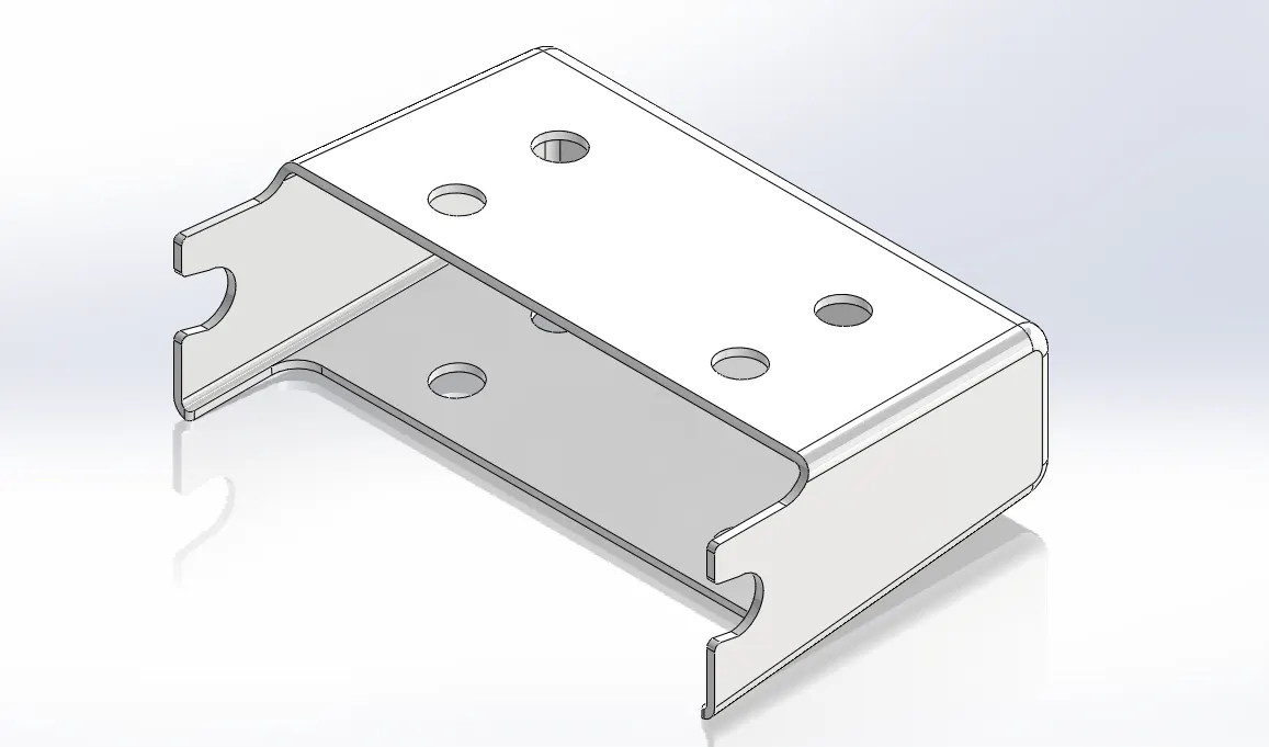
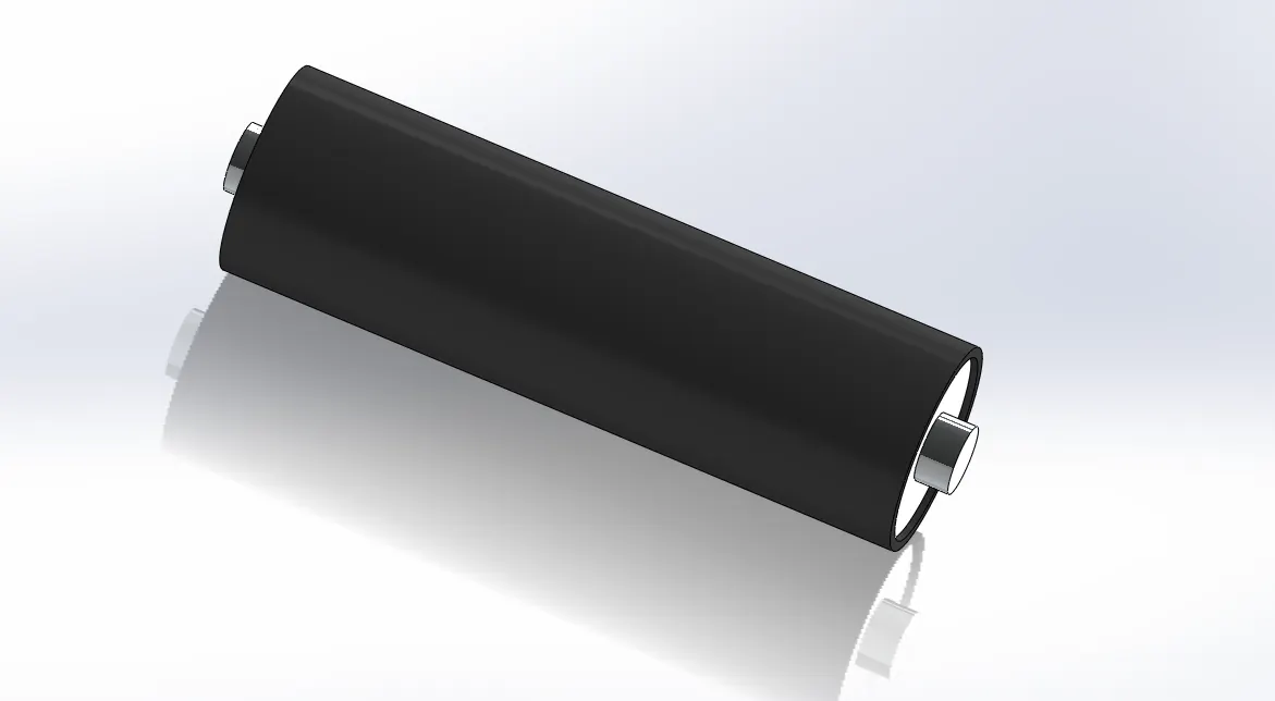
Deflecting Pulley-
This is a plastic molding component assembly. Which is assembled by bearing and axle.
Tools and features used-
- Revolved Boss/base
Part Image-
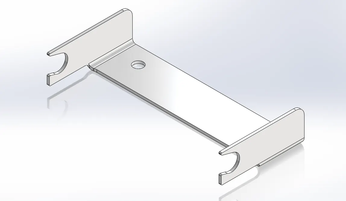
Lower Bearing Block-
This is an Lower bearing block, which is part of sheet metal.
Which is mounted on the base plate in bottom side.
In which the deflecting pulley is assembled
Tools and features used-
- Base Flange
- Edge Flange
- Extruded cut
- Fillets
Part Image-
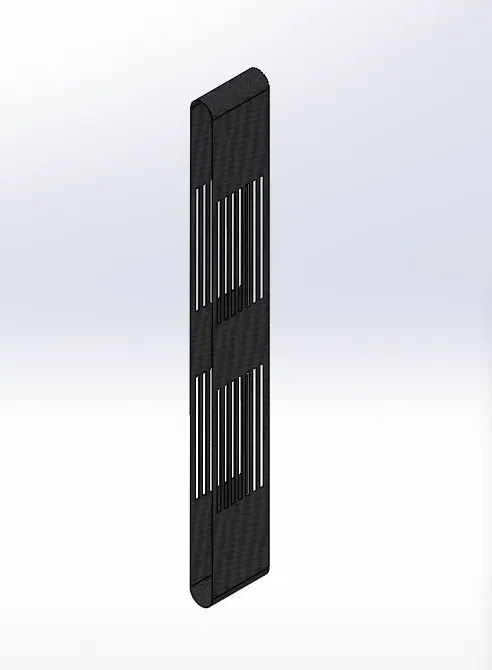
Heddle Belt-
This is a Fabric. which is rotates the Deflecting Pulley.
Tools and features used-
- Extruded boss/base
- Extruded cut
Part Image-
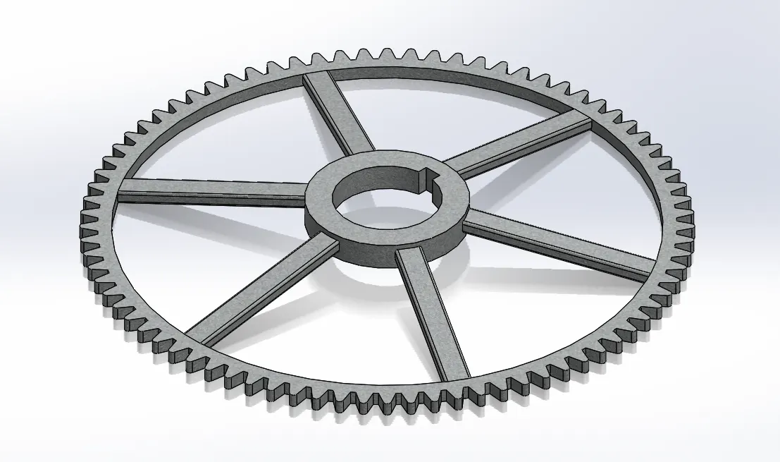
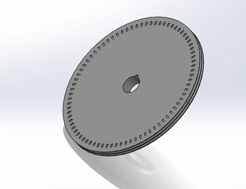
Sensor Wheel-
This is the sensor wheel. It is used to calculate the RPM of the machine.
It is mounted on the main adapter shaft below the base plate.
Tools and features used-
- Extruded boss/base
- Extruded cut
- 3D sketch
- Circular Pattern
- Combine
- Fillets
Part Image-
Machine Pulley-
It is made by casting and machining.
Which is mounted on the main adapter shaft.
And it is connected to the motor pulley by V-belt.
Tools and features used-
- Extruded boss/base
- Extruded cut
- Sweep cut
- Circular pattern
- Fillets
Part Image-
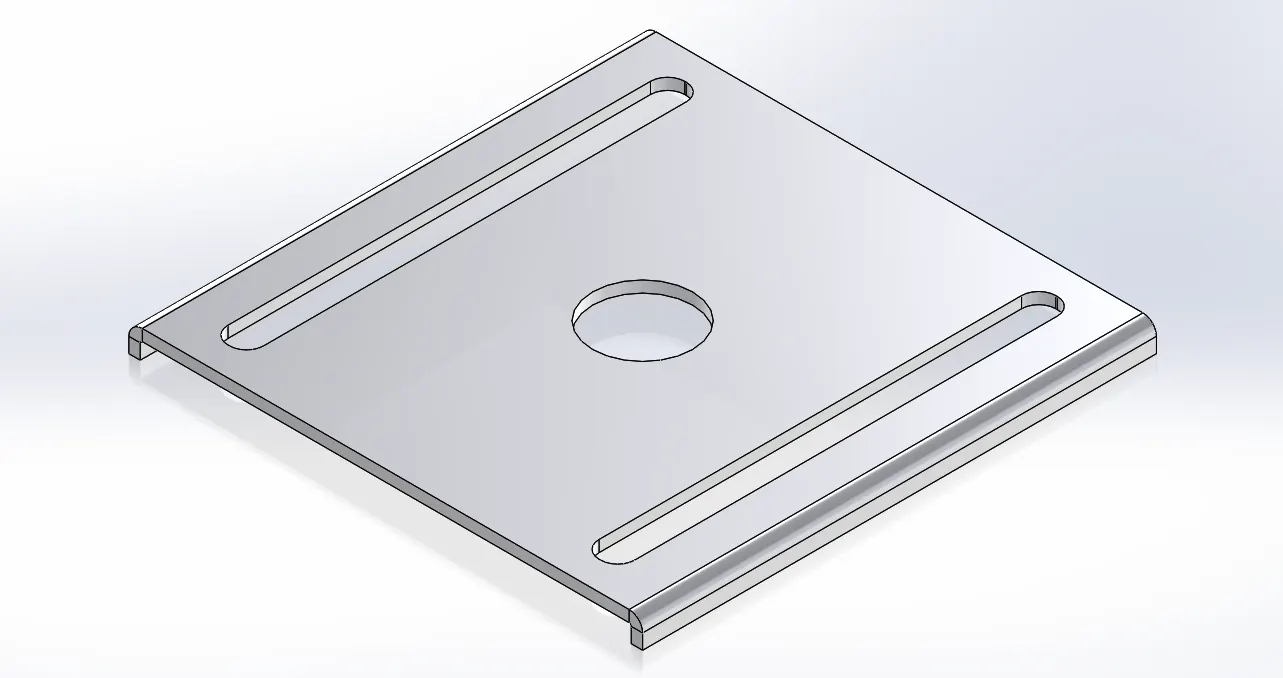
Motor Plate-
This is a sheet metal part. On which there is a slot on the plate to adjust the motor tension with the machine pulley.
Tools and features used-
- Base Flange
- Edge Flange
- Fillets
Part Image-
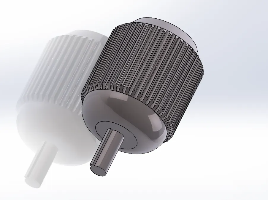
Motor-
it is a main motor, by which rotates the machine pulley
Tools and features used-
- Extruded boss/base
- Extruded cut
- Revolved Boss/base
- Revolved Cut
- Circular Pattern
Part Image-
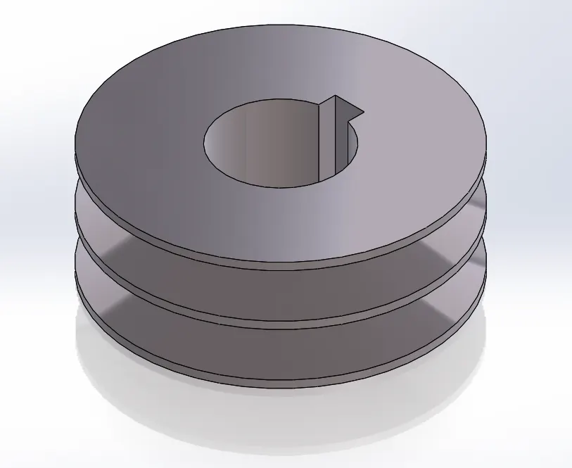
Motor Pulley-
It is made by casting and machining.
Which is mounted on the main motor shaft.
And it is connected to the Machine pulley by V-belt.
Tools and features used-
- Extruded boss/base
- Revolved Cut
Part Image-
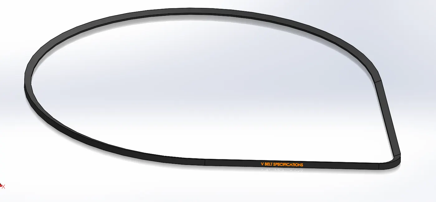
V-Belt-
It is a V-belt it has made by rubber.
it is connected to the motor pulley and machine pulley.
Tools and features used-
- Extruded boss/base
- Extruded cut
- Sweep cut
Part Image-
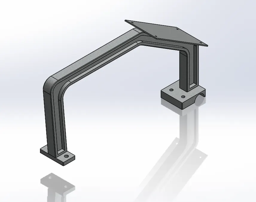
Upper Ring Stand-
It is made by casting and machining.
Which is mounted on the Lower ring stand.
A plate is welded to the switch box assembly on the ring-stand.
Tools and features used-
- Extruded boss/base
- Extruded cut
- Fillets
Part Image-
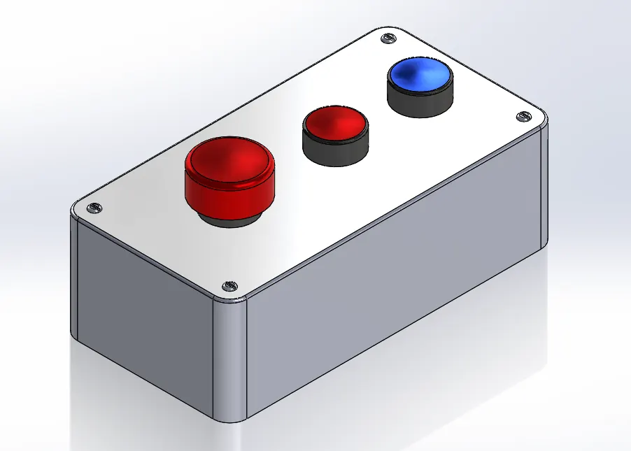
Switch Box-
This is a plastic component. Which is mounted on the upper ring stand. This box is used to start and stop the machine.
Tools and features used-
- Extruded boss/base
- Extruded cut
- Dome
- Fillets
Part Image-
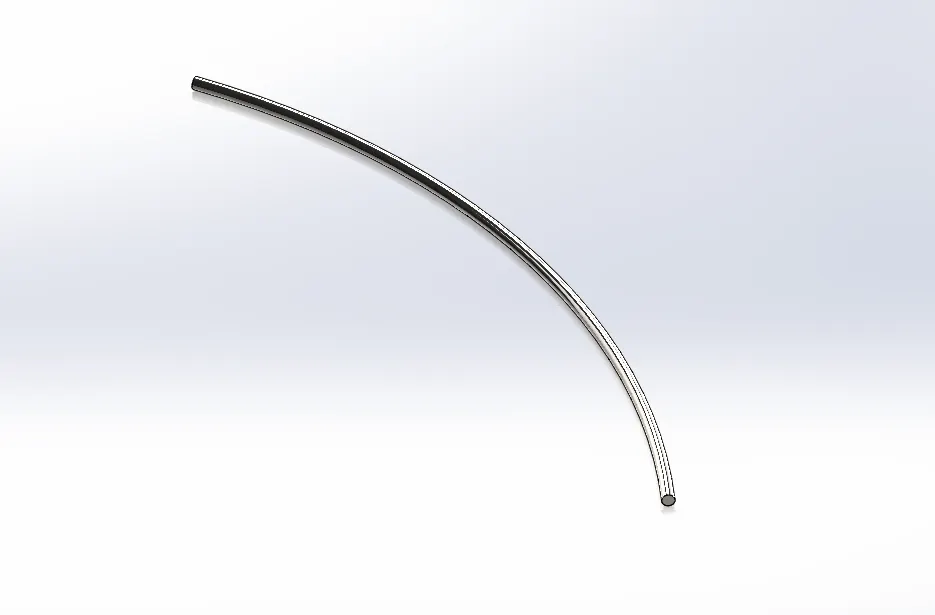
Compensitor Wire-
It is a metallic rod, it is bent into a radius, which is called compensator wire.
Tools and features used-
- Sweep Boss/base
- Extruded cut
Part Image-
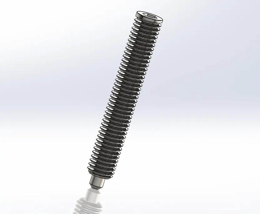
Tension Bolt-
This is the stud, that is mounted on the upper bearing block, through which the tension of the heddle belt is provided.
Tools and features used-
- Revolved Boss/base
- Extruded Boss/base
- Extruded cut
- Chamfer
- fillets
- Thread
Part Image-
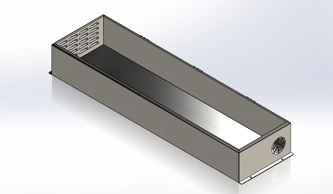
Control Panel Box-
This is part of the sheet metal.
In which equipment like PLC, exhaust fan, SMPS, relay are installed to control the machine.
Tools and features used-
- Base Flange
- Edge Flange
- Vent
- Louver
- Linner Pattern
- Extruded Boss/Base
- Extruded cut
Part Image-
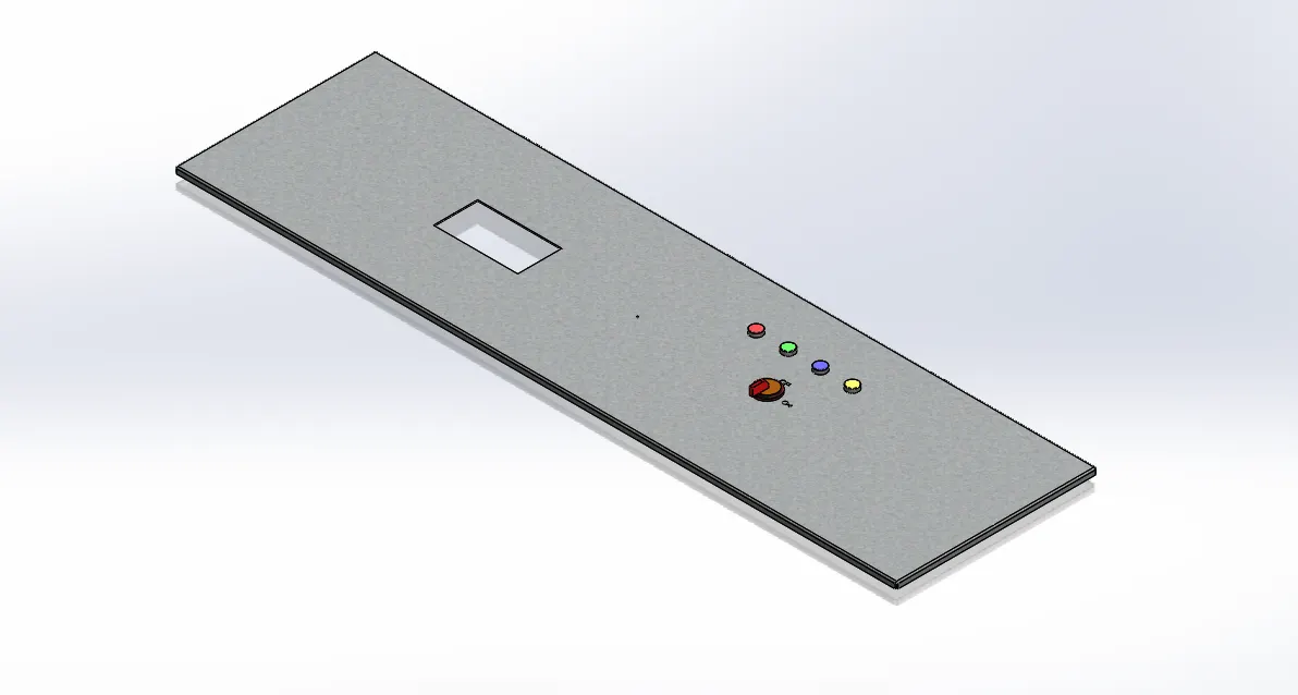
Control Panel Box Cover-
This is the cover of the control panel box. Which is made of sheet metal,
on the cover of which HMI and main switches are installed.
Tools and features used-
- Base Flange
- Edge Flange
- fillets
- Extruded Boss/Base
- Extruded cut
- Linner Pattern
Part Image-
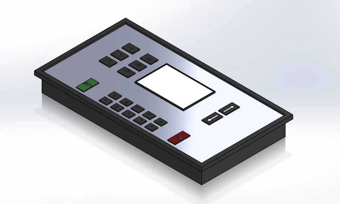
HMI-
A Human-Machine Interface (HMI) is a user interface or dashboard that connects a person to a machine, system, or device. While the term can technically be applied to any screen that allows a user to interact with a device, HMI is most commonly used in the context of an industrial process.
Tools and features used-
- Base Flange
- Edge Flange
- fillets
- Extruded Boss/Base
- Extruded cut
- Linner Pattern
Part Image-
Vertical Column-
This is made of sheet metal part.
Tools and features used-
- Base Flange
- Edge Flange
Part Image-
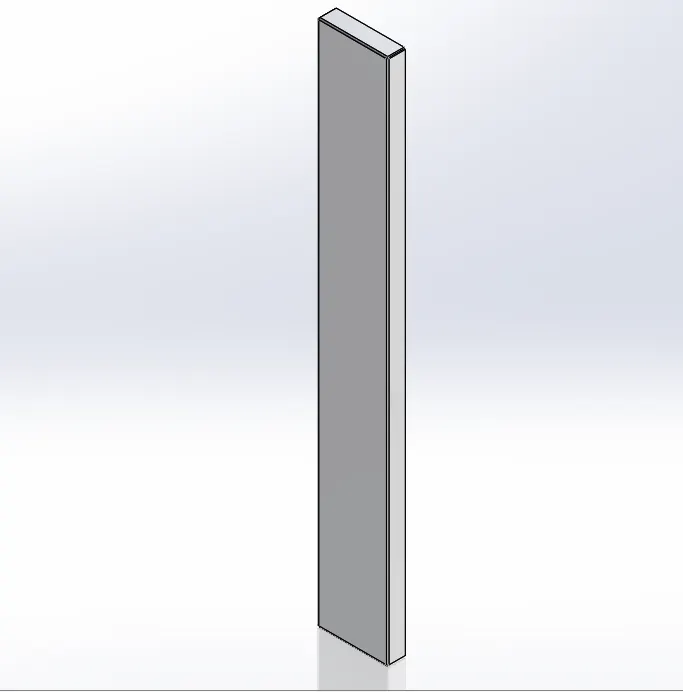
Top Column-
This is made of sheet metal part.
Tools and features used-
- Base Flange
- Edge Flange
- Extruded cut
Part Image-
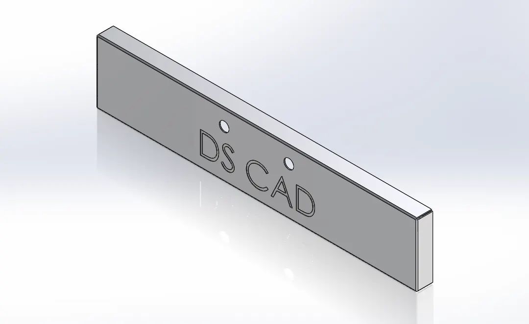
Side Column-
This is made of sheet metal part. by which joint the top & vertical column.
Tools and features used-
- Base Flange
- Edge Flange
Part Image-
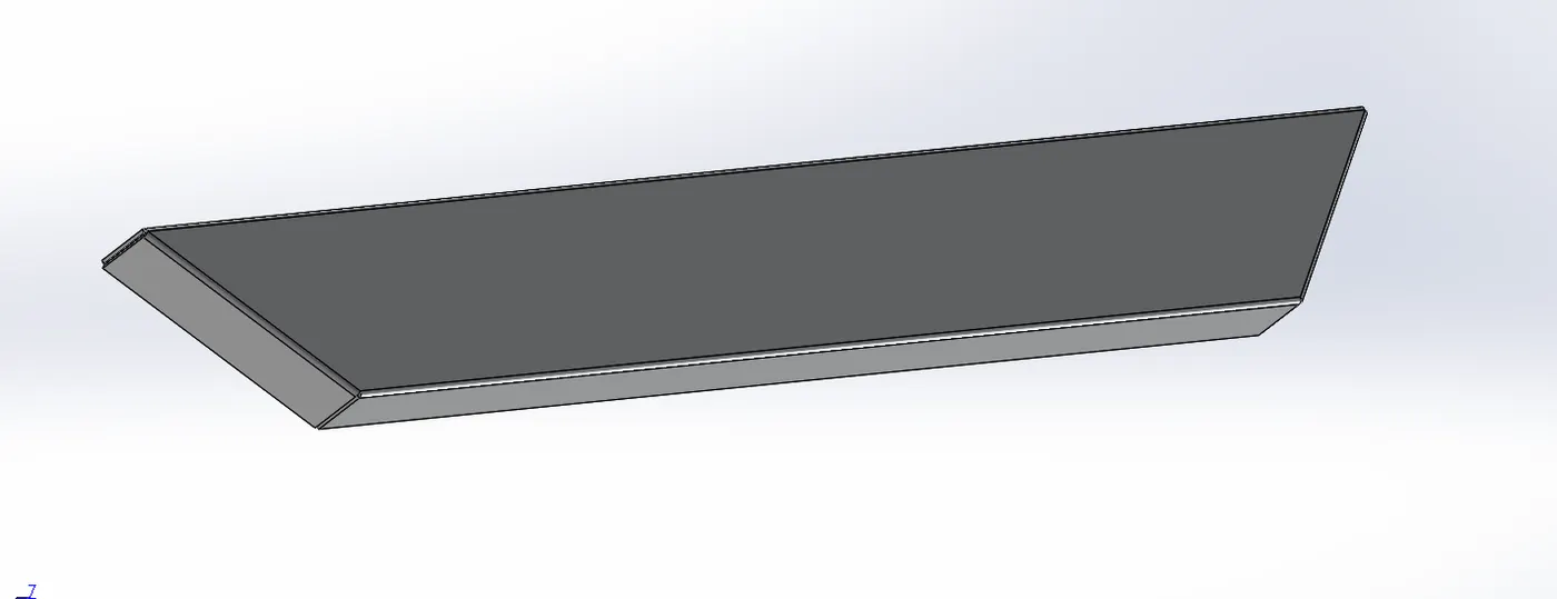
Column Support-
This is made of sheet metal part. for give the support of the vertical column.
Tools and features used-
- Base Flange
- Edge Flange
- Tab
- Fillets
Part Image-
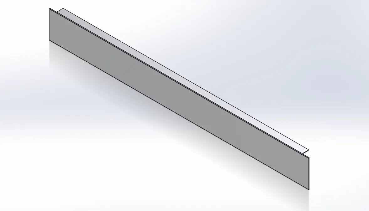
Fabric Roller-
This is the fabric roller to tension the fabric on the upper side. which is mounted of the Top column.
Tools and features used-
- Revolved Boss/base
- Exturded cut
- Mirror
Part Image-
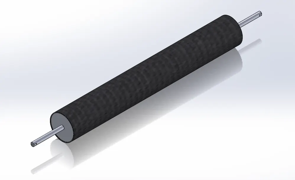
Bobbin (Creel Stand)-
This is stand of the creel. In which creel has been installed and the bobbin has been inserted in the creel.
Tools and features used-
- Sketch
- 3D sketch
- Pipe 26.9x3.2(6)
Part Image-
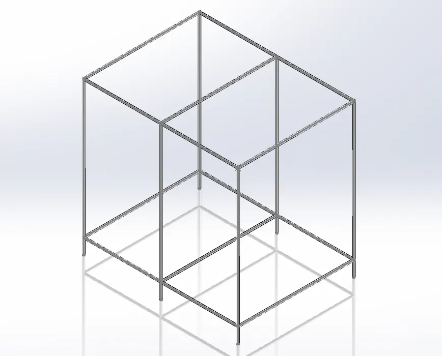
Creel & Bobbin-
This is a pipe in which a rod is welded to insert the bobbin. And the creel is fitted into the creel frame.
Tools and features used-
- Sweep Boss/base
- Linner Pattern
- Mirror
- Extruded boss/base
Part Image-
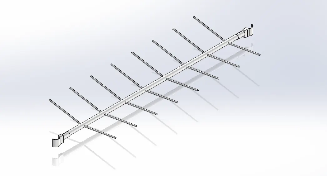
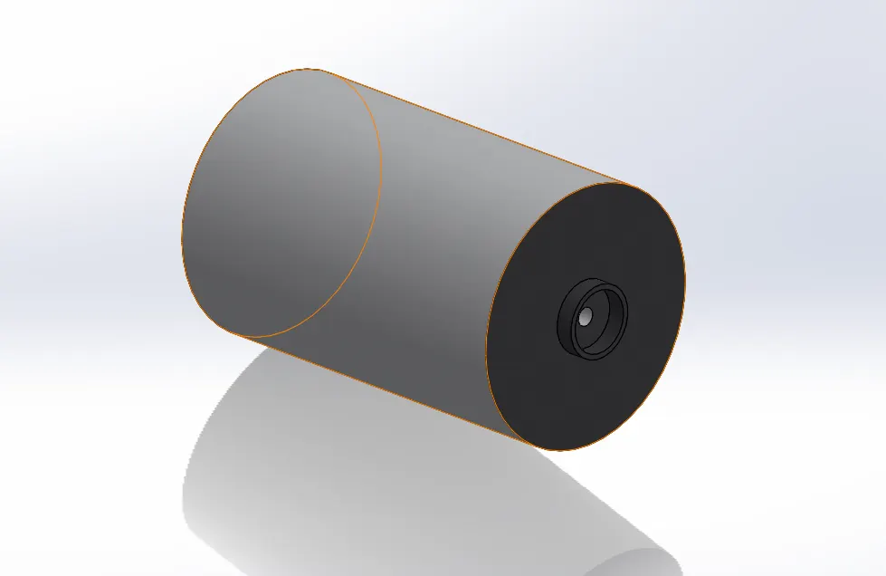
Winder Assembly-
Winder is a rolling equipment, which rolls the fabric.
Tools and features used-
- Sweep Boss/base
- Base Flange
- Edge Flange
- Mirror
- Extruded boss/base
- Extruded cut
- Curve
- Fillets i.e.
Part Image-
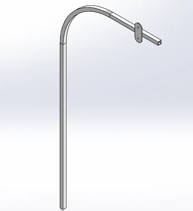
Connecting Pipe-
This is the connecting pipe that connects the winder to the creel stand.
Tools and features used-
- Sweep Boss/base
- Extruded boss/base
Part Image-
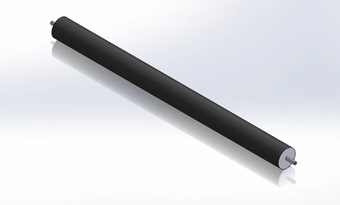
Roller-
This is the fabric roller to tension the fabric for rolling fabric on the winder.
Tools and features used-
- Revolved Boss/base
Part Image-
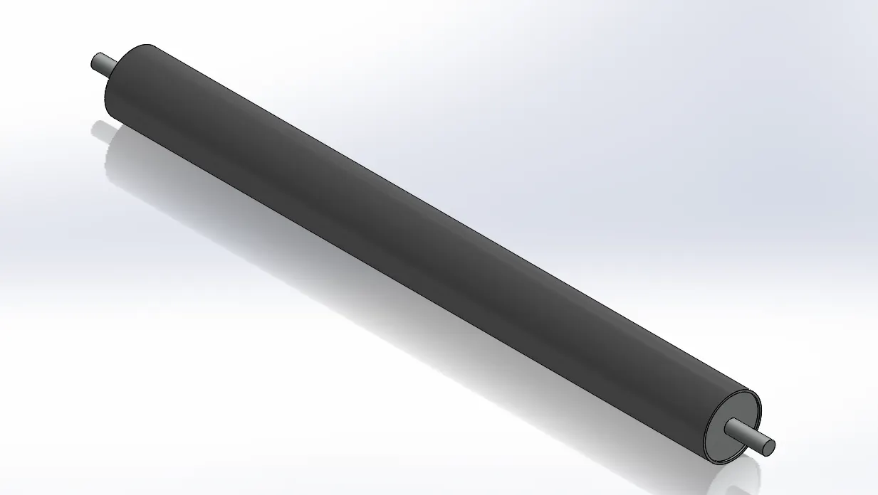
Pressure Roller-
This is the Pressure roller. It keeps the fabric coming from the bobbin in tension.
Tools and features used-
- Revolved Boss/base
Part Image-
Circular Weaving Machine:-
- Circular weaving machines are manufactured with continuously circulating shuttles which run around the periphery; with this system shuttle seed is limited.
- This system allows several shuttles used at the same time which results in increase of productivity.
- The uniform speed of weft package eliminates package faults like slough-off.
- The major disadvantage with this method is that the fabric formed is less flexible in width and has narrow range of options.
- Generally polyolefin and polypropylene tape yarns are used for production of fabric by this method.
Working & Construction-
- To understand working and construction of circular weaving, consider the above figure which shows a cross- section through Ancet-Fayolle loom.
- Two beams are used to supply the warp which passes around the back rest and then I is spread into circular form in the series of lose reeds as shown in the figure and the warp shed is formed from this point.
- There is an arrangement provided showing eight shuttles which are equally spaced around the loom, in circular loom the major advantage is that multiple number of shuttles can be used at single time.
- Then, the appropriate positions of thirty-two pairs of harnesses are indicated which will be required to weave plain weave.
- The continuous lines shown in the above mention figure represents the harness that control one set of alternate ends and the dotted lines show the position on other ends.
- A series of electromagnetic block is allowed to rotate on a motor driven main center shaft.
- The use of electromagnets attracts the metal shuttles which then follows the magnet in the circular path.
- The intervening of warp shed prevents the attraction of shuttles into coming in physical contact with the electromagnets.
- In this loom, automatic weft replenishment is not possible, the use of temples make sure that early contraction of fabric is prevented.
- The number of shuttles used per loom is not fixed and it varies loom to loom.
- The number of shuttles used is decided by that the diameter of the loom as it determines the space available in the warp shed and thus the number of shuttle per loom
- Usually plain and twill weaves are possible n this type of loom.
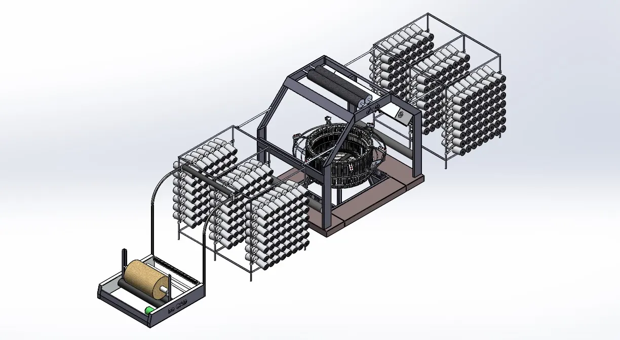
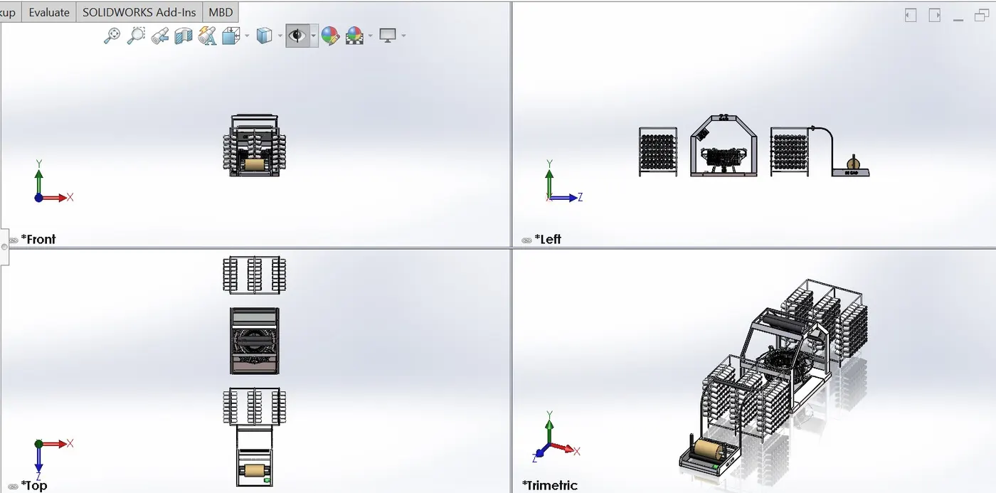
Views:-
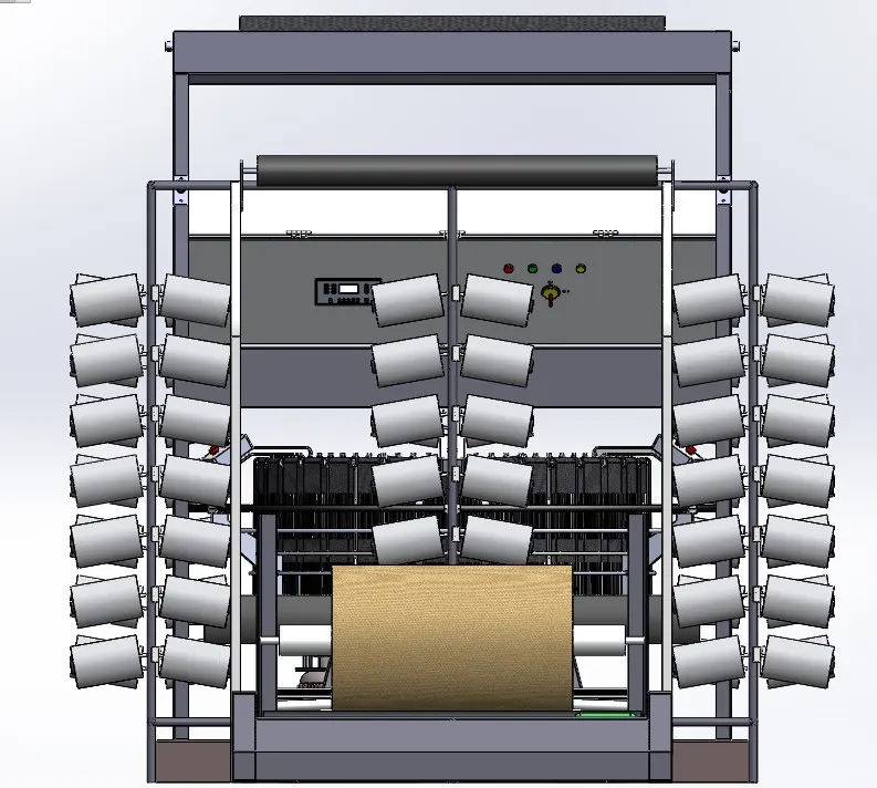
Fornt View-
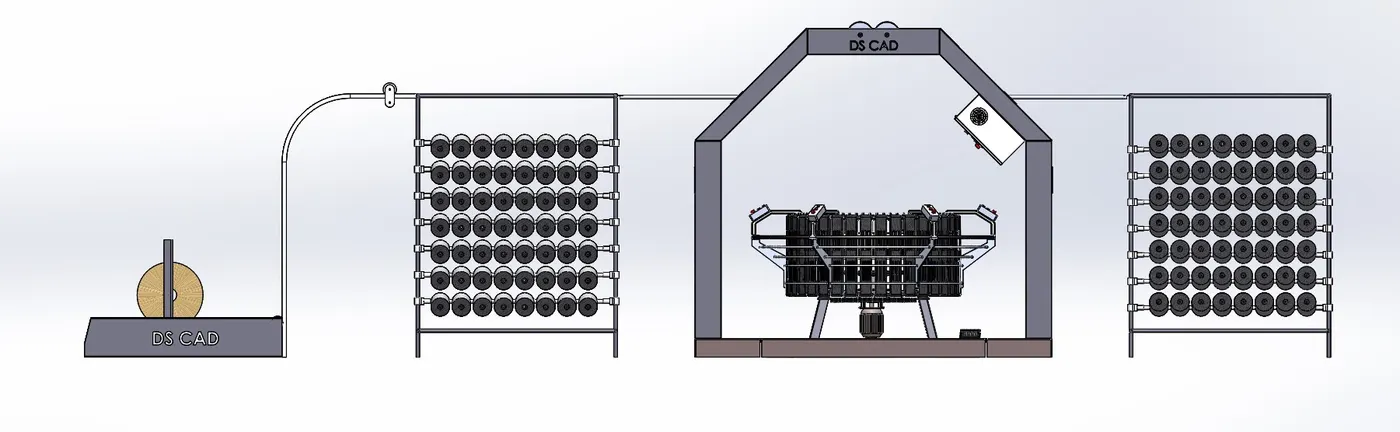
Left View-
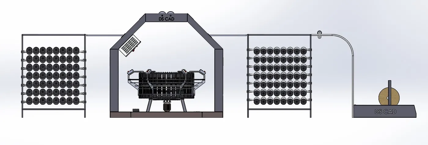
Right View-
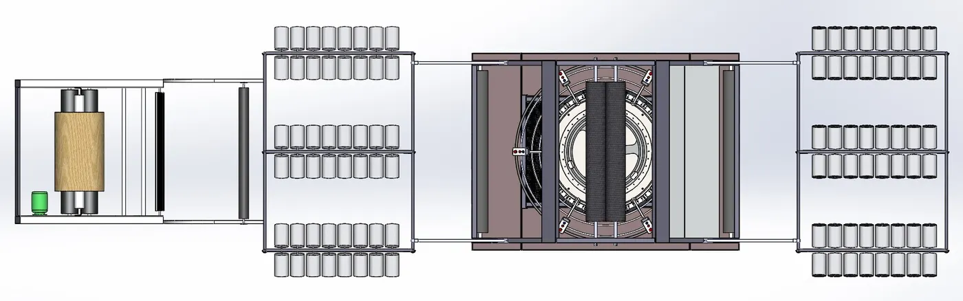
Top View-
Iso-metric View-
Rendering Images:-
Conclusion:-
Modelling each parts and assembly is done.
Rendering image is done.