FINAL INDEPENDENT PROJECT
Aim:
To design and assemble the Air Piston Cylinder Assembly.
Objective:
Theory:
A air piston-cylinder assembly for displacing a load through a long stroke consists of a rod, a piston slidable on the rod and by fluid pressure the piston is clamped to the rod, and a cylinder in which the piston is contained.
COMPRESSED AIR ENGINE BASICS:
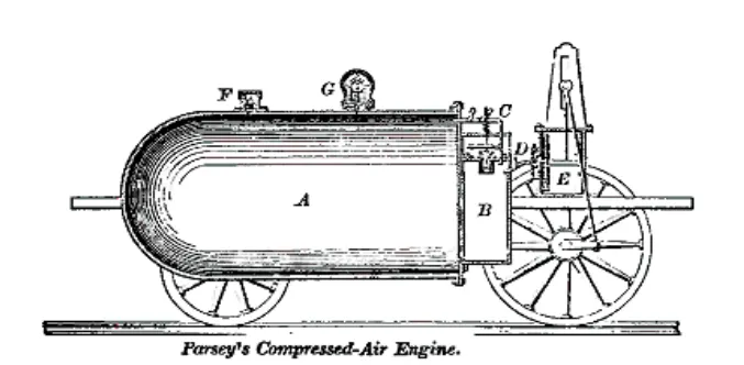
A Compressed-air engine is a pneumatic actuator that creates useful work by expanding compressed air. A compressed-air vehicle is powered by an air engine, using compressed air, which is stored in a tank. Instead of mixing fuel with air and burning it in the engine to drive pistons with hot expanding gases, compressed air vehicles (CAV) use the expansion of compressed air to drive their pistons. They have existed in many forms over the past two centuries, ranging in size from hand held turbines up to several hundred horsepower. For example, the first mechanically-powered submarine, the 1863 Plongeur, used a compressed air engine.
The laws of physics dictate that uncontained gases will fill any given space. The easiest way to see this in action is to inflate a balloon. The elastic skin of the balloon holds the air tightly inside, but the moment you use a pin to create a hole in the balloon's surface, the air expands outward with so much energy that the balloon explodes. Compressing a gas into a small space is a way to store energy. When the gas expands again, that energy is released to do work. That's the basic principle behind what makes an air car go.Some types rely on pistons and cylinders, others use turbines. Many compressed air engines improve their performance by heating the incoming air, or the engine itself. Some took this a stage further and burned fuel in the cylinder or turbine, forming a type of internal combustion engine.
One manufacturer claims to have designed an engine that is 90 percent efficient. Compressed air propulsion may also be incorporated in hybrid systems, e.g., battery electric propulsion and fuel tanks to recharge the batteries. This kind of system is called hybrid-pneumatic electric propulsion. Additionally, regenerative braking can also be used in conjunction with this system.
HISTORY:
a) The first compressed-air vehicle was devised by Bompas, a patent for a locomotive being taken out in England in 1828. There were two storage tanks between the frames, with conventional cylinders and cranks. It is not
clear if it was actuallybuilt. (Knight, 1880).
b) The first recorded compressed-air vehicle in France was built by the Frenchmen Andraud and Tessie of Motay in 1838. A car ran on a test track at Chaillot on the 9th July 1840, and worked well, but the idea was not pursued further.
c) In 1848 Barin von Rathlen constructed a vehicle which was reported to have beendriven from Putney to Wandsworth (London) at an average speed of 10 to 12 mph.
d) At the end of 1855, a constructor called Julienne ran some sort of vehicle at Saint-Denis in France, driven by air at 25 atmospheres (350 psi), for it to be used in coal mines.
e) Compressed air locomotives were use for haulage in 1874 while the Simplon tunnel was being dug. An advantage was that the cold exhaust air aided the ventilation of the tunnel.
f) Louis Mékarski built a standard gauge self-contained tramcar which was tested in February 1876 on the Courbevoie-Etoile Line of the Paris Tramways Nord (TN), where it much impressed the current president and minister of transport Maréchal de MacMahon. The tramcar was also shown at the exhibition of 1878 as it seemed to be an ideal transport method, quiet, smooth, without smoke, fire or the possibility of boiler explosion.
.
g) The compressed-air locos were soon withdrawn due to a number of accidents, possibly caused by icing in the pipes of the brakes, which were also worked by compressed air.
h) In Louis Mékarski built a standard gauge self-contained tramcar which was tested in February 1876 on the Courbevoie-Etoile Line of the Paris Tramways Nord (TN), where it much impressed the current president and minister of transport Maréchal de MacMahon. The tramcar was also shown at the exhibition of 1878 as it seemed to be an ideal transport method,
quiet, smooth, without smoke, fire or the possibility of boiler explosion.
APPLICATIONS:
The compressed air engine can be used in many vehicles. Some of its applications to be used as engine for vehicles are:
a) Mopeds Jem Stansfield, an English inventor has been able to convert a regular scooter to a compressed air moped. This has been done by equipping the scooter with a compressed air engine and air tank.
b) Buses MDI makes MultiCATs vehicle that can be used as buses or trucks. RATP has also already expressed an interest in the compressed-air pollution-free bus.
c) Locomotives Compressed air locomotives have been historically used as mining locomotives and in various areas.
d) Trams Various compressed-air-powered trams were trialed, starting in 1876 and has been successfully implemented in some cases.
e) Watercraft and aircraft Currently, no water or air vehicles exist that make use of the air engine. Historically compressed air engines propelled certain torpedoes.
ADVANTAGES:
The advantages are well publicised since the developers need to make their machines attractive to investors. Compressed-air vehicles are comparable in many ways to electric vehicles, but use compressed air to store the energy instead of batteries. Their potential advantages over other vehicles include:
a) Much like electrical vehicles, air powered vehicles would ultimately be powered through the electrical grid, which makes it easier to focus on reducing pollution from one source, as opposed to the millions of vehicles on the road.
b) Transportation of the fuel would not be required due to drawing power off the electrical grid. This presents significant cost benefits. Pollution created during fuel transportation would be eliminated.
c) Compressed air technology reduces the cost of vehicle production by about 20%, because there is no need to build a cooling system, fuel tank, Ignition Systems or silencers.
d) Air, on its own, is non-flammable.
e) High torque for minimum volume.
f) The mechanical design of the engine is simple and robust.
g) Low manufacture and maintenance costs as well as easy maintenance.
h) Compressed-air tanks can be disposed of or recycled with less pollution than batteries.
i) Compressed-air vehicles are unconstrained by the degradation problems associated with current battery systems.
j) The tank may be able to be refilled more often and in less time than batteries can be recharged, with re-fuelling rates comparable to liquid fuels.
k) Lighter vehicles would mean less abuse on roads. Resulting in longer lasting roads.
l) The price of fuelling air-powered vehicles will be significantly cheaper than current fuels.
DISADVANTAGES:
Like the modern car and most household appliances, the principal disadvantage is the indirect use of energy. Energy is used to compress air, which - in turn - provides the energy to run the motor. Any conversion of energy between forms results in loss. For conventional combustion motor cars, the energy is lost when oilis converted to usable fuel - including drilling, refinement, labour, storage, eventually transportation to the end-user. For compressed-air cars, energy is lost when electrical energy is converted to compressed air.
a) When air expands, as it would in the engine, it cools dramatically (Charleslaw) and must be heated to ambient temperature using a heat exchanger similar to the Intercooler used for internal combustion engines. The heating is necessary in order to obtain a significant fraction of the theoretical energy output. The heat exchanger can be problematic. While it performs a similar task to the Intercooler, the temperature difference between the incoming air and the working gas is smaller. In heating the stored air, the device gets very cold and may ice up in cool, moist climates.
b) Refuelling the compressed air container using a home or low-end conventional air compressor may take as long as 4 hours though the specialized equipment at service stations may fill the tanks in only 3 minutes.
c) Tanks get very hot when filled rapidly. SCUBA tanks are sometimes immersed in water to cool them down when they are being filled. That would not be possible with tanks in a car and thus it would either take a long time to fill the tanks, or they would have to take less than a full charge, since heat drives up the pressure.
d) Early tests have demonstrated the limited storage capacity of the tanks; the only published test of a vehicle running on compressed air alone was limited to a range of 7.22 km.
e) ) A 2005 study demonstrated that cars running on lithium-ion batteries outperform both compressed air and fuel cell vehicles more than three-fold at same speeds. MDI has recently claimed that an air car will be able travel 140km in urban driving, and have a range of 80 km with a top speed of 110.
Procedure:
Mass Properties:
Mass properties ofAIR PISTON CYLINDERASSEMBLY
Configuration: Default
Coordinate system: Coordinate System1
Mass = 3.49 pounds
Volume = 12.40 cubic inches
Surface area = 85.37 square inches
Center of mass: ( inches )
X = 1.45
Y = 1.43
Z = 1.98
Principal axes of inertia and principal moments of inertia: ( pounds * square inches )
aTken at the center of mass.
Ix = (-0.25, -0.01, 0.97) Px = 3.31
Iy = (-0.97, -0.02, -0.25) Py = 9.78
Iz = ( 0.02, -1.00, 0.00) Pz = 1.13
Moments of inertia: ( pounds * square inches )
aTken at the center of mass and aligned with the output coordinate system. Lxx = 9.37Lxy = 0.03Lxz = -1.57
Lyx = 0.03 Lyy = 11.13 Lyz = -0.05
Lzx = -1.57 Lzy = -0.05 Lzz = 3.72
Moments of inertia: ( pounds * square inches )
aTken at the output coordinate system.
Ixx = 30.13 Ixy = 7.28 Ixz = 8.45
Iyx = 7.28 Iyy = 32.13 Iyz = 9.81
Izx = 8.45 Izy = 9.81 Izz = 18.21
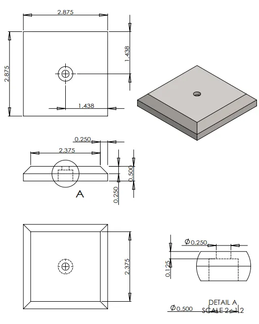
1.Base:
The base model performed using this dimensions.
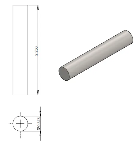
2.Connecting Rod:
The connceting rod model performed using this dimensions.
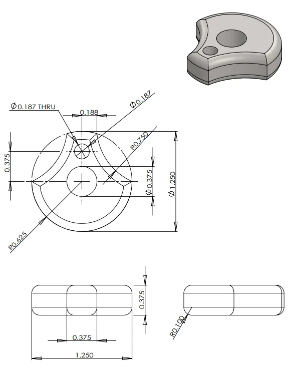
3.Shaft Wheel:
The shaft wheel model performed using this dimensions.
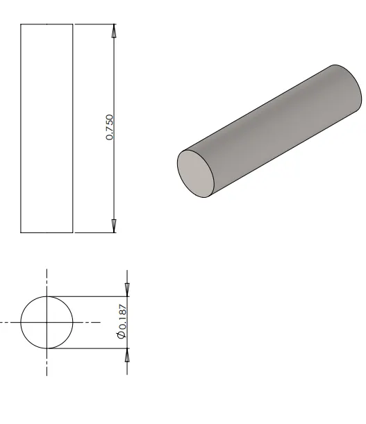
4.Small bar:
The small bar model performed using this dimensions.
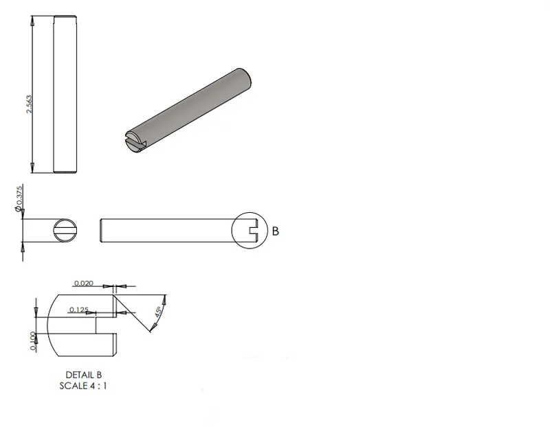
5.Big Bar:
The big bar model performed using this dimensions.
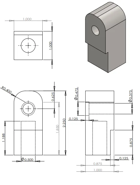
6.Cylinder:
The cylinder model performed using this dimensions.
7.Main Body:
The main body model performed using this dimensions.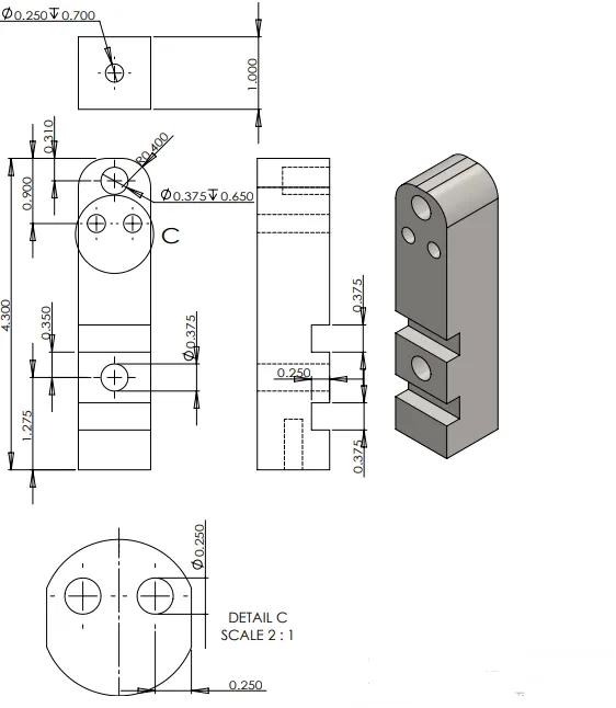
8.Holder:
The holder model performed using this dimensions.
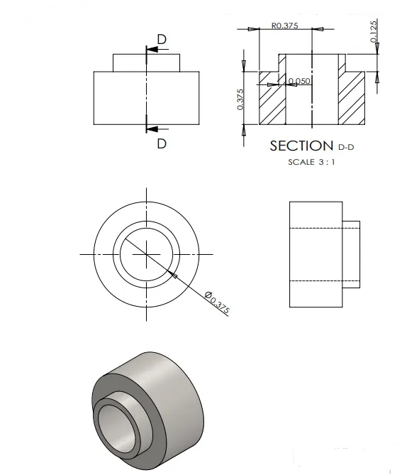
9.Piston:
The piston model performed using this dimensions.
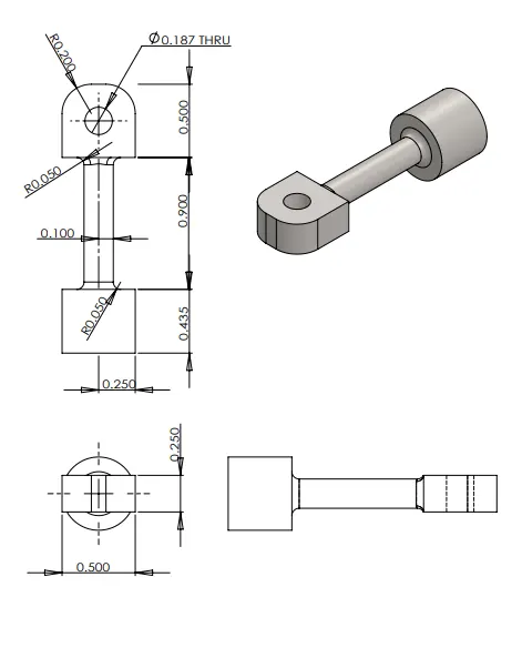
10.Fly wheel:
The fly wheel model performed using this dimensions.
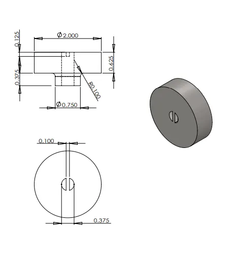
11.Bolt:
The bolt model performed using this dimensions.
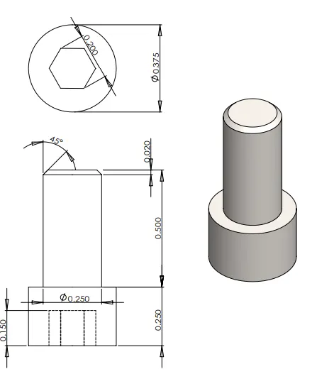
Final Assembly: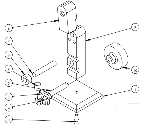
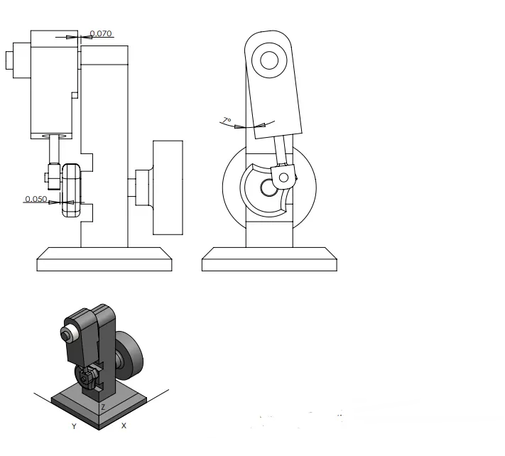
Result:
Thus the air piston cylinder assembly is designed sucessfully.
Google Drive Link: https://drive.google.com/drive/folders/1aeonJ41Pnne-DbLJ-qOP6h5zU0aksGxr?usp=sharing