FINAL INDEPENDENT PROJECT
Aim:
- To calculate the displacement of the beam due to boundary condition and applied load at any point of the beam.
- To find the node iso-parametric beam element to solve the deflection.
- In order to coding I’m using MATLAB R2021b.
Objective:
- To implementing a code which solves cantilever beam and simply supported beam with point load at any location of the beam.
- There may be supports at any location of the beam accept cantilever with one side fixed. And for simply supported beam point load at any loaction of the beam.
- To calculate the displacement of both beams due to the Force acting on it.
Theory:
Cantilever beam: A cantilever beam is a rigid structural element supported at one end and free at the other, the cantilever beam may be made of concrete or steel with one end cast or anchored to a vertical support. It is a horizontal beam structure whose free end is exposed to vertical load.
Application of cantilever:
- This beam is a structural element that is capable of sensing load mainly by resistance against bending.
- The bending force was induced in the beam’s material as a result of the external load, own span load and external reactions of these loads.
- Internally, the beams experience compressive, tensile and shear stresses as a result of the loads applied to them.
- We compared stress and natural frequency for different materials with the same I, C and T cross-sectional beams.
- Steel, stainless steel, and cast iron cantilever beams undergo static and modal analysis.
- To maintain the beam within a safe operating environment, it must be designed with high stiffness and damping capacity.
Advantages:
- These beam enables erection with little disturbance in navigation.
- The span can be longer than simple beams because beams can be added to the cantilever arms.
- The beam is resting on the arms, it is quite simple to maintain thermal expansion and ground motion.
- The cantilever arms are very stiff due to their depth.
- They are very simple to construct.
- Only one fixed support is required, support on the opposite side is not required.
Disadvantages:
- Like beams, they maintain shear shape along with resistance to large tensile and compressive forces therefore relatively large in scale.
- Truss construction is used in large structures to reduce weight.
Simply Supported beam:
A simply supported beam has 2 supports: hinge and roll. It is very often used in all kinds of constructions. Often the loads are uniform loads, also called continuous loads, this can be dead loads as well as temporary loads. They cause stress inside the beam and deflection of the beam.
This website calculates free and online the stress-strain analyses on a simply supported beam.
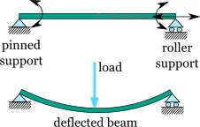
The simply supported beam is one of the most simple structures. It features only two supports, one at each end. One is a pinned support and the other is a roller support. With this configuration, the beam is inhibited from any vertical movement at both ends whereas it is allowed to rotate freely. Due to the roller support it is also allowed to expand or contract axially, though free horizontal movement is prevented by the other support.
Removing any of the supports inserting an internal hinge, would render the simply supported beam to a mechanism, that is body the moves without restriction in one or more directions. Obviously this is unwanted for a load carrying structure. Therefore, the simply supported beam offers no redundancy in terms of supports, and if a local failure occurs the whole structure would collapse. These type of structures that offer no redundancy are called critical or determinant structures. To the contrary, a structure that features more supports than required to restrict its free movements is called redundant or indeterminate structure.
Methodology:
Equilibrium equation: ∑ Fᠲ= 0.
Now assuming no axial load is -> Vs+ds – Vs +f(s)ds = 0.
So after differentiating we get -> dVs/ds +f = 0.
Alos assuming the bending moment is 0 then the equation ->
Ms+ds –Ms + Vs+ds*ds + f ds * ds/2 = 0.
Now taking limds - 0
We get,
dMs/ds +Vs = 0
hence d^2m/ds^2 = f
so the deflection equation of the beam is d^2w/ds^2 = M(s)/EI
So after combining the Equilibrium eq and the deflection of beam we get
d^2/ds^2(EI d^2w/ds^2) = f
(This eq is known as Euler-Bernoulli Beam equation)
Slope = dw/ds is specified
Moment at s = 0 is Mo
V = shear force at s=0 = Vo
w is a function of s
Here, w = deflection of the beam,
E = Young’s Modulus
I = moment of area
M = a function of s
s = variable varying along length of beam
This is called principle of virtual work.
Shape Function: the shape function defines the deflection as a function of s. They are w(s) = w1N1(s) + theta1*1N2(s) + w2 N3(s) + theta2*2 N4(s)
where N1(s), N2(s), N3(s) and N4(s) are the shape functions and are defined as
Le = length of element
Zeta = s/Le
So,
N1(s) = 1- 3 (zeta)^2 + 2(zeta)^3
N2(s) = Le(zeta – 2(zeta)^2 + (zeta)^3)
N3(s) = 3(zeta)^2 – 2(zeta)^3
N4(s) = 4(-(zeta)^2 +(zeta)^3)
These are called hermite polynomials and the elements formulated using these are called Hermite Elements
Using the above polynomials and the weak form of the beam equation, the elemental equation of a beam can be written as
[Ke]*{Xe} = {Fe}
[Ke] = [12 6Le -12 6Le;6Le 4Le2 -6Le 2Le2; -12 -6Le 12 -6Le;6Le 2Le2 -6Le 4Le2]
{Xe} = {w1 theta1 ᡵ2 theta2} = displacement matrix.
{Fe} = {Fc} + {Fd}
{Fd} = forces due to uniformly distributed loads and {Fc} = general force and moment matrix.
Hence assembling the above for all the elements of the entire beam, we can calculate the displacements and forces at each elements. We can use two approaches
Penalty method: The penalty method to the finite element method is analyzed. A variational principle for this model problem on spaces of functions not satisfying the boundary conditions is studied and, based on this principle, a variant of the finite element method is given.
Eliminating unknown rows and columns: In elimination method, all predefined displacements must be eliminated since the solutions are already known. This will reduce the order number of matrix. Other remaining equations are then adjusted due to the elimination.
Now using the later method we have to solve for element of beam displacement and find their reaction.
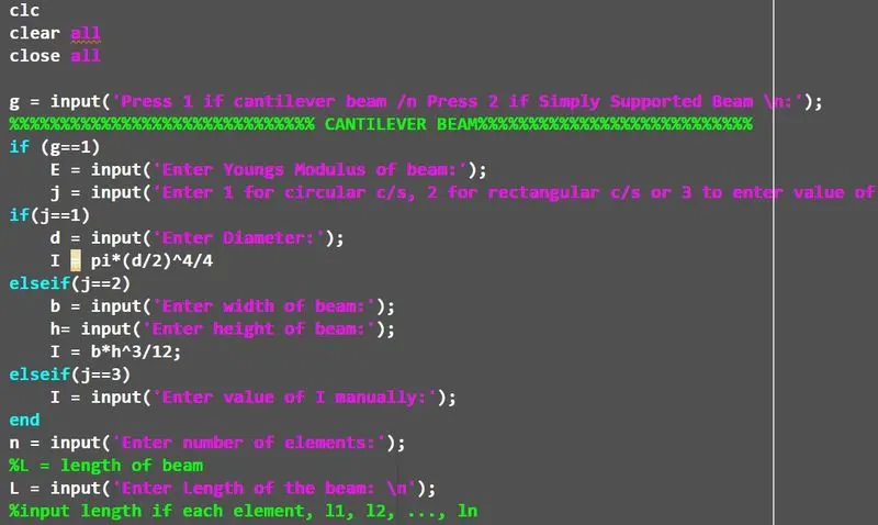
Main Code:
clc
clear all
close all

g = input('Press 1 if cantilever beam /n Press 2 if Simply Supported Beam \n:');
%%%%%%%%%%%%%%%%%%%%%%%%%%%%%% CANTILEVER BEAM%%%%%%%%%%%%%%%%%%%%%%%%%%%
if (g==1)
    E = input('Enter Youngs Modulus of beam:');
    j = input('Enter 1 for circular c/s, 2 for rectangular c/s or 3 to enter value of I manually:');
if(j==1)
    d = input('Enter Diameter:');
    I = pi*(d/2)^4/4
elseif(j==2)
    b = input('Enter width of beam:');
    h= input('Enter height of beam:');
    I = b*h^3/12;
elseif(j==3)
    I = input('Enter value of I manually:');
end
n = input('Enter number of elements:');
%L = length of beam
L = input('Enter Length of the beam: \n');
%input length if each element, l1, l2, ..., ln
%l = [3; 3];
for i=1:n
    fprintf('element %g', i);
    l(i)=input('Enter length of element :');
end
%k = E*I/le^3*[12 6*le -12 6*le; 6*le 4*le^2 -6*le 2*le^2; -12 -6*le 12 -6*le; 6*le 2*le^2 -6*le 4*le^2]
%enter boundary condition at each node
%K2 = zeros(6,6);
if n == 1
    le = l(i);
    K = E*I/le^3*[12 6*le -12 6*le; 6*le 4*le^2 -6*le 2*le^2; -12 -6*le 12 -6*le;
    6*le 2*le^2 -6*le 4*le^2];
%K = wextend(2,'zpd',k,2, 'r');
else
for i = 1:n-1
    if (i == 1)
    le = l(i);
    k = E*I/le^3*[12 6*le -12 6*le; 6*le 4*le^2 -6*le 2*le^2; -12 -6*le 12 -6*le;
    6*le 2*le^2 -6*le 4*le^2];
    K = wextend(2,'zpd',k,2, 'r');
else
    K = wextend(2,'zpd',K,2, 'r');
end
    le = l(i+1);
    k = E*I/le^3*[12 6*le -12 6*le; 6*le 4*le^2 -6*le 2*le^2; -12 -6*le 12 -6*le;
    6*le 2*le^2 -6*le 4*le^2];
    K1 = wextend(2,'zpd',k,2*i, 'l');
    K= K+K1;
end
end
% Reduced stiffness matrix   % To calculate the Stiffness matrix
K2 = K;
ds = zeros((2*(n+1)),1);
for i = n+1:-1:2
    fprintf('Node %g \n', i);
    l = input('Press 1 if support is there for this node, 0 if no support is there: \n');
if (l == 1)
    K2((i-1)*2+1,:) = [];
    K2(:,(i-1)*2+1) = [];
    ds((i-1)*2+1) = 1;
end
end
ds(1)=1;
ds(2)=1;
K2(1:2,:) = [];
K2(:,1:2) = [];

% Calculating the Force matrix
r = size(K2,1)
fprintf('Enter all the forces in order, first enter force and then moment for all nodes: \n');
for i = 1:r
 F(i) = input('');
end
a = 1;
%displacements
dis = inv(K2)* F'
for i = 1:2*(n+1)
  if(ds(i)==1)
    ds(i)=0;
else
    ds(i)=dis(a);
    a=a+1;
end
end
fprintf(' the displacements at the the nodes are: ')
fprintf('the reactions at the nodes are:')
Fr = K*ds;  %Force reaction
w=1;
N = [];
for i = 1:n
  l(i) = le;
for s = 0:(0.1*le):le
 if (i~=1)&(s~=0)
    zeta = s/le;
    N1 = (1-3*zeta^2+2*zeta^3);
    N2 = le*(zeta-2*zeta^2+zeta^3);
    N3 = (3*zeta^2-2*zeta^3);
    N4 = le*(-zeta^2+zeta^3);
    N = vertcat(N, [N1, N2, N3, N4]);
    f = ds(((2*i)-1),1) * N1 + ds((2*i),1) * N2 + ds(((2*i)+1),1) * N3 + ds(((2*i)+2),1) * N4;
    t(w)=f;
    w=w+1;
elseif (i==1)
    zeta = s/le;
    N1 = (1-3*zeta^2+2*zeta^3);
    N2 = le*(zeta-2*zeta^2+zeta^3);
    N3 = (3*zeta^2-2*zeta^3);
    N4 = le*(-zeta^2+zeta^3);
    N = vertcat(N, [N1, N2, N3, N4]);
    f = ds(((2*i)-1),1) * N1 + ds((2*i),1) * N2 + ds(((2*i)+1),1) * N3 + ds(((2*i)+2),1) * N4;
    t(w)=f;
    w=w+1;
end
end
end
x=1
for u = 0:(0.1*L/n):L
    lbh = u;          % lbh shows the length of the beam diplaced in graph
    lb(x) = lbh;
    lbd(x) = 0;
    x=x+1;
end

% Plotting
plot(lb, t, 'r', lb, lbd, 'k')
else
%%%%%%%%%%%%%%% SIMPLY SUPPORTED BEAM %%%%%%%%%%%%%%%%%%%%%%%%%%
E = input('Enter Youngs Modulus of beam:');
j = input('Enter 1 for circular c/s, 2 for rectangular c/s or 3 to enter value of I manually:');
if(j==1)
    d = input('Enter Diameter:');
    I = pi*(d/2)^4/4
elseif(j==2)
    b = input('Enter width of beam:');
    h= input('Enter height of beam:');
    I = b*h^3/12
elseif(j==3)
    I = input('Enter value of I manually:');
end
n = input('Enter number of elements:');
%L = length of beam
L = input('Enter Length of the beam: \n');
%input length if each element, l1, l2, ..., ln
%l = [3; 3];
for i=1:n
   l(i)=input('Enter length of element :');
end
%k = E*I/le^3*[12 6*le -12 6*le; 6*le 4*le^2 -6*le 2*le^2; -12 -6*le 12 -6*le; 6*le 2*le^2 -6*le 4*le^2]
%enter boundary condition at each node
%K2 = zeros(6,6);
for i = 1:n-1
    if (i == 1)
        le = l(i);
        k = E*I/le^3*[12 6*le -12 6*le; 6*le 4*le^2 -6*le 2*le^2; -12 -6*le 12 -6*le; 6*le 2*le^2 -6*le 4*le^2];
        K = wextend(2,'zpd',k,2, 'r');
    else
        K = wextend(2,'zpd',K,2, 'r');
    end
    le = l(i+1);
    k = E*I/le^3*[12 6*le -12 6*le; 6*le 4*le^2 -6*le 2*le^2; -12 -6*le 12 -6*le; 6*le 2*le^2 -6*le 4*le^2];

    K1 = wextend(2,'zpd',k,2*i, 'l');
    K= K+K1;
end
% Calculation Stiffness matrix
K2 = K;
ds = zeros((2*(n+1)),1);
for i = n:-1:2
    fprintf('Node %g \n', i);
    l = input('Press 1 if support is there for this node, 0 if no support is there: \n');
  if (l == 1)
    K2((i-1)*2+1,:) = [];
    K2(:,(i-1)*2+1) = [];
    ds((i-1)*2+1) = 1;
end
end
ds(1)=1;
%ds(2)=1;
K2(1,:) = [];
K2(:,1) = [];

% Calculating force matrix
r = size(K2,1);
K2(r-1,:) = [];
K2(:,r-1) = [];
ds(r)=1;
r = size(K2,1);
fprintf('Enter all the forces in order, first enter force and then moment for all nodes');
for i = 1:r
  F(i) = input('\n ');
end
a = 1;
%displacements
dis = inv(K2)* F';
for i = 1:2*(n+1)
    if(ds(i)==1)
    ds(i)=0;
    else
    ds(i)=dis(a);
    a=a+1;
    end
end
Fr = K*ds;
w=1
N = [];
for i = 1:n
  l(i) = le;
for s = 0:(10):le
if (i~=1)&(s~=0)
    zeta = s/le;  % In force reaction consisting of an angular moment
    N1 = (1-3*zeta^2+2*zeta^3);
    N2 = le*(zeta-2*zeta^2+zeta^3);
    N3 = (3*zeta^2-2*zeta^3);
    N4 = le*(-zeta^2+zeta^3);
    N = vertcat(N, [N1, N2, N3, N4]);
    f = ds(((2*i)-1),1) * N1 + ds((2*i),1) * N2 + ds(((2*i)+1),1) * N3 + ds(((2*i)+2),1) * N4;
    t(w)=f;
    w=w+1;
elseif (i==1)
    zeta = s/le;
    N1 = (1-3*zeta^2+2*zeta^3);
    N2 = le*(zeta-2*zeta^2+zeta^3);
    N3 = (3*zeta^2-2*zeta^3);
    N4 = le*(-zeta^2+zeta^3);
    N = vertcat(N, [N1, N2, N3, N4]);
    f = ds(((2*i)-1),1) * N1 + ds((2*i),1) * N2 + ds(((2*i)+1),1) * N3 + ds(((2*i)+2),1) * N4;
    t(w)=f;
    w=w+1;
end
end
end
x=1
for u = 0:(10):L
    lbh = u;      % lbh shows the length of the beam diplaced in graph
    lb(x) = lbh;
    lbd(x) = 0;
    x=x+1;
end
% Plotting
plot(lb, t, 'r', lb, lbd, 'k')
end
% Calculation of the max displacement
ans = F*L^3/(3*E*I);
Explanation:
- a) Enter the cross section of beam, whether circular or rectangular and calculate I (moment of area). If the moment is available enter the value directly.
b) Input the length of beam, number of elements we wish to divide the beam into, length
of each element, etc.
c) Calculate the element stiffness matrix and assemble that into global stiffness matrix.
d) Input if there is a support at a node other than the fixed one for the cantilever.
e) If there is a support, remove the row and column corresponding to the vertical displacement and store the reduced stiffness matrix as the displacement is constrained in y direction but angular displacement is allowed.
f) After that remove the first and second row and column of the reduced global stiffness matrix as the angular and vertical displacements are constrained on the first node as there is a cantilever support.
g) Input the forces or moments that are acting on the beam in order starting from first If no force or moment is acting, input zero at that node.
h) After obtaining the reduced stiffness matrix and the force matrix, multiply the inverse of the reduced stiffness matrix and force matrix to obtain the nodal displacements.
i) Calculate the shape functions and using the nodal displacements of the beam, find the displacements along the elements and plot the displacements to obtain the deflection
of the beam.
3) Else if a simply supported beam,
Repeat steps till e) above.
f) Now remove the second and the last second row and column of the reduced stiffness matrix.
Repeat steps g) through i) above and obtain the final deflection of the beam
Output:
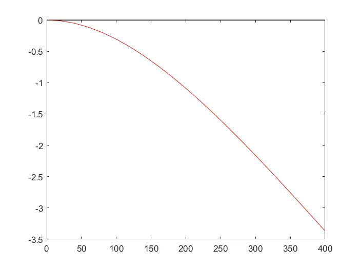
Cantilever Beam:
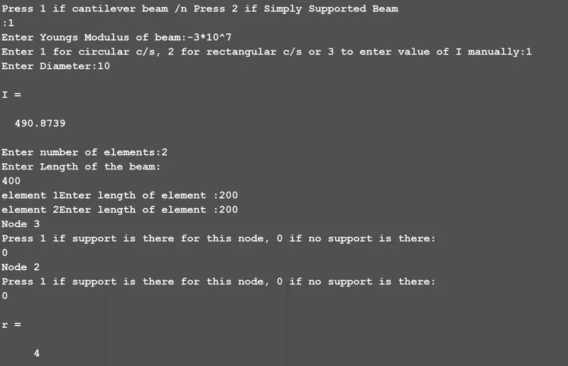
Press 1 if cantilever beam /n Press 2 if Simply Supported Beam
:1
Enter Youngs Modulus of beam:-3*10^7
Enter 1 for circular c/s, 2 for rectangular c/s or 3 to enter value of I manually:1
Enter Diameter:10
I =
490.8739
Enter number of elements:2
Enter Length of the beam:
400
element 1Enter length of element :200
element 2Enter length of element :200
Node 3
Press 1 if support is there for this node, 0 if no support is there:
0
Node 2
Press 1 if support is there for this node, 0 if no support is there:
0
r =
4
Enter all the forces in order, first enter force and then moment for all nodes:
1000
1500
2000
2500
dis =
-1.0919
-0.0096
-3.3697
-0.0123
the displacements at the the nodes are: the reactions at the nodes are:
x =
1
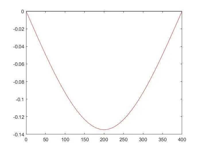
Simply supported Beam:
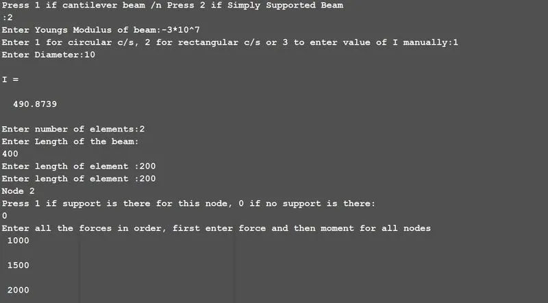
Press 1 if cantilever beam /n Press 2 if Simply Supported Beam
:2
Enter Youngs Modulus of beam:-3*10^7
Enter 1 for circular c/s, 2 for rectangular c/s or 3 to enter value of I manually:1
Enter Diameter:10
I =
490.8739
Enter number of elements:2
Enter Length of the beam:
400
Enter length of element :200
Enter length of element :200
Node 2
Press 1 if support is there for this node, 0 if no support is there:
0
Enter all the forces in order, first enter force and then moment for all nodes
1000
1500
2000
2500
w =
1
x =
1
Plotting:
File:
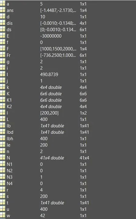
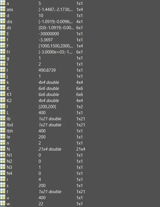
Conclusion:
We conclude that a simple beam may be solved for displacements and reactions easily by hand, but as the loads start varying and the analytical solution by hand becomes difficult. So we implement the finite element analysis to approximate the beam deflection. We saw that the shape function is used to interpolate the deflection at each point in between the element. The finite element solution of a beam element is a cubic polynomial while actual beam solution is of the 4th order. The finite element model gives a stiffer beam. It actually forces the beam in to specific modes of deflection as per the shape functions and hence gives a more stiffer beams. Moreover as we increase the number of nodes, we get a better solution. Here we gained an insight on a beam element, how it behaves, how the stiffness matrix is derived and the final solution. Also the actual implementation of shape functions to get the total deflection of a structure by programming it. Also it gave a deeper sense of how an actual commercial Finite Element software would be getting the solutions and how to better control inputs to a solution of a problem by using FEA.