FINAL INDEPENDENT PROJECT
single slider-crank mechanism:-
slider-crank mechanism, arrangement of mechanical parts designed to convert straight-line motion to rotary motion, as in a reciprocating piston engine, or to convert rotary motion to straight-line motion, as in a reciprocating piston pump.
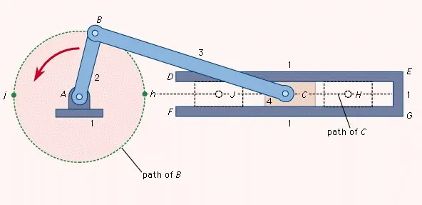
- The basic nature of the mechanism and the relative motion of the parts can best be described with the aid of the accompanying figure, in which the moving parts are lightly shaded.
- The darkly shaded part 1, the fixed frame or block of the pump or engine, contains a cylinder, depicted in cross section by its walls DE and FG, in which the piston, part 4, slides back and forth.
- The small circle at A represents the main crankshaft bearing, which is also in part 1. The crankshaft, part 2, is shown as a straight member extending from the main bearing at A to the crankpin bearing at B, which connects it to the connecting rod, part 3.
- The connecting rod is shown as a straight member extending from the crankpin bearing at B to the wristpin bearing at C, which connects it to the piston, part 4, which is shown as a rectangle.
- The three bearings shown as circles at A, B, and C permit the connected members to rotate freely with respect to one another.
- The path of B is a circle of radius AB; when B is at point h the piston will be in position H, and when B is at point j the piston will be in position J.
- On a gasoline engine, the head end of the cylinder (where the explosion of the gasoline-air mixture takes place) is at EG; the pressure produced by the explosion will push the piston from position H to position J; return motion from J to H will require the rotational energy of a flywheel attached to the crankshaft and rotating about a bearing collinear with bearing A.
- On a reciprocating piston pump the crankshaft would be driven by a motor.
Aim:-
To create animation of single slider-crank mechanism by using matlab
Theory:-
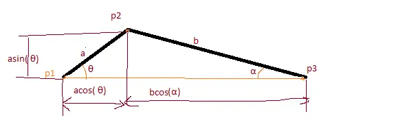
a=length of crank
b=length of connecting rod (slider)
p1=point at center of crank(0,0)
p2=point at intersection of a&b (acosθ,asinθ)
p3=point at sliding(acosθ+bcosα ,0)
p1 at rest ,p2 at rotating motion ,p3 at reciprocating motion
calculating of α (alpha)
from laws of sine
`frac{a}{sinalpha}=frac{b}{sintheta}`
`alpha=sin^-1(a*frac{sintheta}{b})`
code:-
clear all
close all
clc
% lengths of the crank and slider
a=2
b=5
%point p1
p1=[0 0];
%parameters of plot
axis(gca,'equal');%aspect ratio
axis([-2 8 -2 3]);
%angular speed of crank in rad/sec
k=1;
% to built sliding point and boundaries
e=0;
sx=0.5;
sy=0.5;
fixupper=line([a+b+sx+1 b-a-sx-0],[e+sy e+sy],'color','b','linewidth',1);
fixlower=line([a+b+sx+1 b-a-sx-0],[e-sy e-sy],'color','b','linewidth',1);
% Now comes the loop
for t=1:500  % t is the time in tenths of seconds
    theta=k*(t/10)
    %point p2
    p2=a*[cos(theta) sin(theta)];
    %calculating the alfa
    alfa=asin(a*sin(theta)/b);
    %point p3
    p3=[(a*cos(theta)+b*cos(alfa)) 0];
    % connecting the line b/w p1&p2
    crank=line([p1(1) p2(1)],[p1(2) p2(2)],'color','black','linewidth',5);
    % connecting the line b/w p2&p3
    slider=line([p2(1) p3(1)],[p2(2) p3(2)],'color','black','linewidth',5);
    %imaginery center line b/w p1&p3
    center=line([p1(1) p3(1)],[p1(2) p3(2)]);
     %imaginery circle of crank
     p2_traj=viscircles([0 0],a,'linestyle','--');
     % points vissual
    p1_circ=viscircles(p1,0.01);
    p2_circ=viscircles(p2,0.1);

    %p3 point indication as a piston
    piston=line([p3(1) p3(1)],[p3(2)+sy p3(2)-sy],'color','b','linewidth',50);

    p3_circ=viscircles(p3,0.05);
    % all images getting frame
    drawnow
    F(t)=getframe(gcf);
    pause(0.001);
     delete(crank);
     delete(p1_circ);
     delete(p2_circ);
     delete(piston);
     delete(slider);
     delete(p3_circ);
end
% video saved to hard drive with 'sliding.avi' filename
video=VideoWriter('sliding.avi','uncompressed AVI');
open(video)
writeVideo(video,F);
close(video)


clear all
close all
clc
% lengths of the crank and slider
a=2
b=5
%point p1
p1=[0 0];
%parameters of plot
axis(gca,'equal');%aspect ratio
axis([-2 8 -2 3]);
%angular speed of crank in rad/sec
k=1;
% to built sliding point and boundaries
e=0;
sx=0.5;
sy=0.5;
fixupper=line([a+b+sx+1 b-a-sx-0],[e+sy e+sy],'color','b','linewidth',1);
fixlower=line([a+b+sx+1 b-a-sx-0],[e-sy e-sy],'color','b','linewidth',1);
% Now comes the loop
for t=1:500  % t is the time in tenths of seconds
    theta=k*(t/10)
    %point p2
    p2=a*[cos(theta) sin(theta)];
    %calculating the alfa
    alfa=asin(a*sin(theta)/b);
    %point p3
    p3=[(a*cos(theta)+b*cos(alfa)) 0];
    % connecting the line b/w p1&p2
    crank=line([p1(1) p2(1)],[p1(2) p2(2)],'color','black','linewidth',5);
    % connecting the line b/w p2&p3
    slider=line([p2(1) p3(1)],[p2(2) p3(2)],'color','black','linewidth',5);
    %imaginery center line b/w p1&p3
    center=line([p1(1) p3(1)],[p1(2) p3(2)]);
     %imaginery circle of crank
     p2_traj=viscircles([0 0],a,'linestyle','--');
     % points vissual
    p1_circ=viscircles(p1,0.01);
    p2_circ=viscircles(p2,0.1);

    %p3 point indication as a piston
    piston=line([p3(1) p3(1)],[p3(2)+sy p3(2)-sy],'color','b','linewidth',50);

    p3_circ=viscircles(p3,0.05);
    % all images getting frame
    drawnow
    F(t)=getframe(gcf);
    pause(0.001);
     delete(crank);
     delete(p1_circ);
     delete(p2_circ);
     delete(piston);
     delete(slider);
     delete(p3_circ);
end
% video saved to hard drive with 'sliding.avi' filename
video=VideoWriter('sliding.avi','uncompressed AVI');
open(video)
writeVideo(video,F);
close(video)
Code Explanation:-
- Initially clear all;close all;clc
- Giving inputs like lengths of links, angular speed.
- pointing p1(0,0).
- drawing the sliding boundaries.
- In for loop t is time and calculating the theta &alfa.
- pointing the p2 and p3 by calculating according to formulae.
- draw the lines of crank and slider &slider shape.
- to capture the vedio by using 'drawnow' and make to get frame of all plots.
- to save vedio 'vedioWriter' command saved to hard drive of pc.
Animation link:-
conclusion:-
single slider-crank mechanism animation is created