FINAL INDEPENDENT PROJECT
Project Title:
DESIGN OPTIMISATION OF A FLAT FINNED HEAT SINK FOR THE ELECTRONIC COMPONENT
Objective: The aim of the project is that the temperature of the electronic component should be maintained below 80 ˚C
when heat rate is 80W & ambient temperature is 30 ˚C. The design of the heat sink should be optimized to minimize the cost of it while respecting all the constraints & design inputs.
Design Inputs:
Dimensions of the Electronic component is 0.07 m X 0.07 m.
1. Length of base (l_Base) = 0.07 m
2. Width of base (w_Base) = 0.07 m
3. Heat Rate (Qt) = 80W
4. Ambient Temperature (T_amb) = 30ºC
5. Convective heat transfer coefficient (h) = 20 W/m^2. K
6. Thermal Contact Resistance between each fin & base (Rtc)= 2X10^-4 m^2.K/W
(Thermal Conductance = 5000 W/m^2.K)
Design Constraints:
1. The maximum height of the heatsink (h) is 0.08 m.
2. The minimum thickness of any fin (t_Fin) is 0.002 m.
3. The minimum distance between any two fins (d_Fin) is 0.003 m.
4. The thickness of the base (t_Base) is fixed at 0.005 m.
Material Data:

About Project:
Components generate heat while in operation. To dissipate heat, components transfer heat through conduction between its solid boundaries and through convection & radition to the surrounding environment. The concept of heat transfer is very well explained by the authot F P Incropera, in his book called Fundamentals of the Heat & Mass Transfer. As per author, when two stationary or moving mediums come in contact heat transferred occur due to temperature differences between two mediums. If both mediums either solid or fluid are stationary heat is transferred from high temperature to low temperature by conduction & if fluid is in motion than heat is dissipate by convection. All surfaces emit energy in the form of electromagnetic waves which is called thermal radiation.
But when component generate heat in excessive amount, they need to transfer heat efficiently & effectively to surrounding medium. The concept of heat transfer is, heat flows from higher temperature to lower temperature. There are multiple ways to increase the heat transfer, first is to increase the heat transfer coefficient by increasing the fluid velocity and second is to decrease the ambient fluid temperature. Both options are not viable in terms of cost because for the first solution it required blower or pump to increase the velocity and second option is impractical. The other option is by increasing the surface area of the component to dissipate the heat with the surrounding.
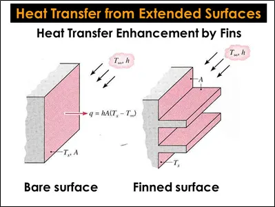
Fins are extended surfaces which increase the total surface area & enhance the heat transfer between the solid & surrounding medium by convection or radiation. Fins are most economical & efficient way to transfer the heat away from the component. Below figure shows how fins increase the heat transfer area compare to normal surface.
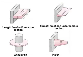
The materials for fins are normally high conductor of heat like Copper, Aluminium. Fins are designed in many different ways depending on the applications. The most used types & shapes are shown in below figure.
Fins can be manufactured from the single block of material or they can be joined with the base. When fins are joined with the base in after manufacturing process, there are chances of thermal contact resistance between the fins & base. Applications where cost is not the priority, than the first case of manufacturing of heat sink from one block of material using CNC machining technique without joining the fins, is the obvious for transferring heat from the components. But in this project, cost minimization is the prime objective, so the fins will be joined with the base after manufacturing them will be the obvious choice. So thermal contact resistance will play their part while heat is transferring from the base to the fins.
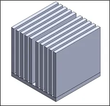
In real application, designer normally used fins array with less fin thickness & more height to increase the surface area, but at the same time decreases the material usage to decrease the cost of the components. The heat sink with the rectangular cross section of the fin & width of the fin will be equal to the width of the base will be used for the current application. The next image shows the similar concept of heat sink.
Application of this type of heat exchanger is in car radiator, electronic components, smaller air cooled engines, electric motors, etc.
Optimization Method Selection:
There are two ways to solve the optimization problem. One is traditional approach & other is non-traditional approach. Kalyanmoy Deb has classified traditional methods, in his research paper, into two groups, 1) Direct Methods & 2) Gradient-based methods. Normally these methods use point by point search approach in solving the problem which is not effective with complex engineering problem. Some problems that associated with these algorithms are, they usually stuck at local optimal solutions, they can’t use in parallel machines, not efficient in handling discrete variables. They designed to solve the specific problem and the same algorithm cannot apply to other types of problems.
The second type is non-traditional or evolutionary algorithm. The most popular algorithms for optimization are Genetic Algorithm, Simulated Annealing, Particle Swarm, Ant Colony, Fuzzy optimization. They followed population-based approach to solve the problem. As per the author & professor D K Pratihar has mentioned in his book, Soft Computing that, Human being has tendency to follow the nature to solve the complex problem the way it has solved it. That’s why, scientists & technologists have developed the optimization problem that adapt the processes developed by the nature over the years like physical processes & biological etc. Most of the problem faced by the traditional methods are easily overcome by the non-traditional methods.
Compare to other evolutionary algorithm, GA has certain advantages like:
- To make the population more diverse, it uses both operators mutation & crossover. That makes it algorithm more preventive to be stuck in the suboptimal solution. This diversity helps it to reach the global optimum point in shorter period of time because diversity helps the algorithm to search the space quicker for the solution.
- GA used higher crossover rate during the beginning of the search to make it more diverse. While toward the end of the space search, populations contain many local optimal points after generations. At the end of the search, it required mutation to search the global optimum from the many local optimum points.
- Same algorithm can be used for many complex engineering applications.
- It doesn’t need any structural information to optimize the function.
- Initial point is not required to start the search, still it can find the optimal solution.
To optimize the heat sink design, the mathematical model needs to be developed & the model will be implemented into the MATLAB software to develop the program to perform the cost minimization function for the heat sink design. For the current heat sink problem Genetic Algorithm (GA) will be the most suitable optimization technique to solve the cost minimization objective.
The working principle of the GA explained by, the creator of MATLAB, MathWorks is as follows:
- The algorithm begins by creating a random initial population.
- The algorithm then creates a sequence of new populations. At each step, the algorithm uses the individuals in the current generation to create the next population. To create the new population, the algorithm performs the following steps:
- Scores each member of the current population by computing its fitness value. These values are called the raw fitness scores.
- Scales the raw fitness scores to convert them into a more usable range of values. These scaled values are called expectation values.
- Selects members, called parents, based on their expectation.
- Some of the individuals in the current population that have lower fitness are chosen as elite. These elite individuals are passed to the next population.
- Produces children from the parents. Children are produced either by making random changes to a single parent—mutation—or by combining the vector entries of a pair of parents—crossover.
- Replaces the current population with the children to form the next generation.
- The algorithm stops when one of the stopping criteria is met.
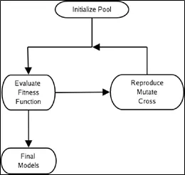
The working of the GA can be explained by following chart as well:
Problem Formulations:
To learn how to optimize the fins for efficiency, effectiveness & cost together & to formulate the data for manufacturing of the heat sink, reference is taken in the form of the book written by F P Incropera called "Fundamentals of the Heat & Mass Transfer" and to understand the working of the Genetic Algorithm, the research paper written by Deb Kalyanmoy called "An introduction to Genetic Algorithm."
The mathermatical model of the heat transfer occurred during the working of the heat sink can be modeled using the following set of formulas:
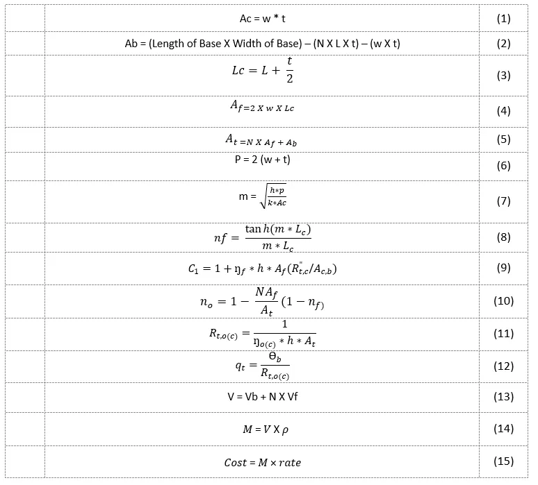
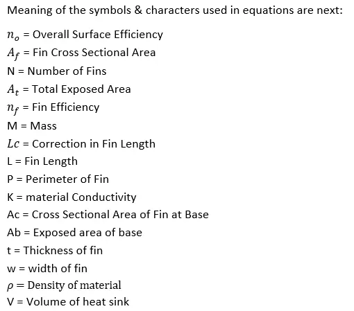
The following assumptions has been considered to simplify the problem:
- Steady state condition.
- One dimensional conduction along the fin.
- Fins have constant properties.
- Heat sink has negligible radiation exchange with the surrounding.
- Heat sink has uniform heat transfer coefficient.
- Consider the heat loss from the fin top is negligible, treat it as adiabatic.
Code:
1. Cost Minimization Program File:
% Project: Design Optimization of Flat Finned Heat Sink for The Electronic
% Component using MATLAB & Genetic Algorithm (GA).

% Writing program for the optimization of the heat sink for the optimimal
% performance & minimizing the manufacturing cost based on given inputs,
% material options & constraints.

% The ojective of the function is to minimize the cost of the Heat Sink.

% Material Options: Copper, Aluminium & Magnesium

% Inputs:
    % Length of base (l_Base) = 0.07 m
    % Width of base (w_Base) = 0.07 m
    % Heat Rate (Qt) = 80W
    % Ambient Temperature (T_amb) = 30ºC
    % Convective heat transfer coefficient (h) = 20 W/m^2. K
    % Thermal Contact Resistance between each fin & base (Rtc)= 2X10^-4 m^2.K/W
    % (Thermal Conductance = 5000 W/m^2.K)

% Constraints:
    % The maximum height of the heatsink (h) is 0.08 m.
    % The minimum thickness of any fin (t_Fin) is 0.002 m.
    % The minimum distance between any two fins (d_Fin) is 0.003 m.
    % The thickness of the base (t_Base) is fixed at 0.005 m.

% Following assumptions has been considered to simplify the optimization
% process
    % Steady state condition.
    % One dimensional conduction along the fin.
    % Fins have constant properties.
    % Heat sink has negligible radiation exchange with the surrounding.
    % Heat sink has uniform heat transfer coefficient.
    % Consider the heat loss from the fin top is negligible, treat it as adiabatic.


clc;

% Problem Settings

% No. of Variables
nvars = 6;

% Boundary Conditions for all design variables
% Lower Bound
lb = [1  0.001 0.002 0.001 1 75];
% Upper Bound
ub = [10 0.07 0.006  0.005 3  80];

% Setting the GA Options for the initial populations, maximum number of
% generations to run the optimization process, maximum number of elite
% individuals, tolerance function & plotting function to plot the best of
% the function for each generation.
opts = gaoptimset(...
        'PopulationSize', 1500, ...
        'Generations', 1000, ...
        'EliteCount', 2, ...
        'TolFun', 1e-8, ...
        'PlotFcns', @gaplotbestf);

 % Using the GA solver, the output of the constraint file(HeatSinkCon.m) &
 % Objective file(HeatSinkObj.m) will be inserted as an input with the
 % additional inputs like upper & lower bounds, integer variables & options
 % for the Genetic Algorithm(opts)
 % xbest is the best value for all design variables will be printed in
 % command window with function best value & the reason to exit the
 % optimization process in the form of exitflag.

[xbest, fbest, exitflag] = ga(@HeatSinkObj,nvars,[],[],[],[],lb,ub,@HeatSinkCon,[1 5],opts)
2. Constraints File:
function [c,ceq] = HeatSinkCon(x)

% Constraints file for the Flat Finned Heat Sink Optiization Problem

% c = Inequality constraints
% ceq = equality constraints

% No. of Variables
N = x(1);     % Number of fin
l_Fin = x(2); % Length of fin in meter
t_Fin = x(3); % Fin Thickness in meter
d_Fin = x(4); % Distance between two fins
mt = x(5);    % Define Material
T_Base = x(6); % Base Temperature

% Parameters
l_Base = 0.07;  % Length of Base in meter
w_Base = 0.07;  % Width of Base in meter
t_Base = 0.005; % Thickeness of Base in meter
w_Fin = 0.07;   % Fin Width in meter
h = 20;         % Convective Heat Transfer Co-efficient (W/m^2. K)
Rtc = 2e-4;     % Thermal Contact Resistence Between Fin & Base (m^2.K/W)
Qt = 80;        % Heat Rate in W
T_amb = 30;     % Ambient Temperature in C

%Supporting Equations

% Cross-sectional area of Fin at Base
Ac  = w_Fin * t_Fin;
% Exposed Surface Area of Base
Ab = (((l_Base * w_Base) - ( N * Ac) )+ (4 * l_Base * t_Base));
% Correction in Fin Length
Lc = l_Fin + (t_Fin/2);
% Exposed Area of Fin
Af = 2 * w_Base * Lc;
% Total Exposed Area
At = (N * Af) + Ab;
% Fin Perimeter
P = 2* (w_Fin + t_Fin);

% Conductivity of Material Selection
% 1 = Copper, 2 = Aluminium, 3 = Magnesium
% k = heat conductivity coefficient in W/mK
if mt == 1
    k = 400;
elseif mt ==2
    k = 240;
elseif mt == 3
    k = 167;
end

% Constant
m = sqrt(((h * P)/(k * Ac)));
% Fin Efficiency
Nf = (tanh(m * Lc))/(m*Lc);
% Constant
C1 = 1 + (Nf * h * Af * ((Rtc)/Ac));
% Overall Surface Efficiency
Noc = 1 - (((N * Af)/At) * (1 - (Nf/C1)));
% Total Thermal Contact Resistance
Rtoc = 1/(Noc * h * At);
% Base Temperature
T_Base = (Qt*Rtoc) + T_amb;

% Inequality Constraint
% Constraint for heat sink height
c1 = l_Fin - 0.075;
% Constraint for fin thickness
c2 = 0.002 - t_Fin;
% Consttraint for minimum distance between two fins
c3 = 0.003 - d_Fin;
% Constraint for maximum allowable temperature at base
c4 = T_Base - 80;
% Constrinats for number of fins
c5 = 1 - N;

c = [c1; c2; c3; c4; c5];

% Equality Constraint
ceq =[];
3. Objective Function File:
function f = HeatSinkObj(x)

% HeatSinkObj calculates the objective function in the Flat Finned Heat Sink
% Optiization Problem
% GA is used as a solver to minimize the cost of the Heat Exchanger

% No. of Variables
N = x(1);     % Number of fin
l_Fin = x(2); % Length of fin in meter
t_Fin = x(3); % Fin Thickne Iss in meter
mt = x(5);    % Define Material

% Parameters
l_Base = 0.07;  % Length of Base in meter
w_Base = 0.07;  % Width of Base in meter
t_Base = 0.005; % Thickeness of Base in meter
w_Fin = 0.07;   % Fin Width in meter

% Selection for Density & Price of the Materials
% 1 = Copper, 2 = Aluminium, 3 = Magnesium
% Roh = Density of the Material in kg/m3
% Rate = Price of the Material in Pound(£) per kg

if mt == 1
    Roh = 8900;
    Rate = 9.25;
elseif mt == 2
    Roh = 2700;
    Rate = 2.6;
elseif mt == 3
    Roh = 1738;
    Rate = 4.00;
end

% Cost Minimizing Function = (Volume of the heat sink X Density X Price of
% the Material
% Volume of the heat sink = Volume of Base + Volume of the all fins
f = ((l_Base * w_Base * t_Base)+(N * l_Fin * t_Fin * w_Fin)) * (Roh) * (Rate);
Results:
1. Command Window:
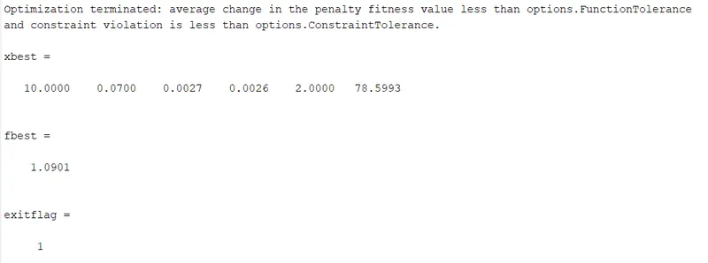
xbest shows the best value for each variable which can be identified as follows:
Number of fins = 10
Length of fins = 0.07m
Thickness of fin = 0.0027m
Distance between 2 fins = 0.0026m
Material = Aluminium (2)
Base temperature = 78.59 C
Function Best Value (fbest) = 1.0901
Reason to exit the optimzation process = 1 (which means the average change in penalty fitness value is less than function tolerance value mentioned in the GA options)
2. Graph:
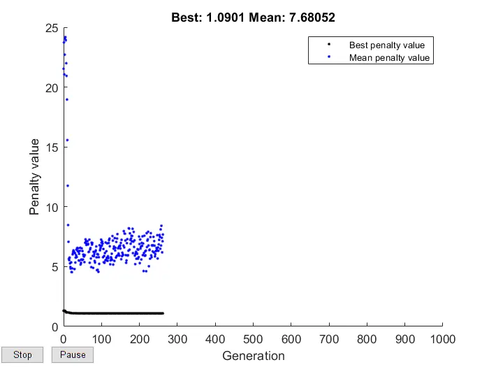
The GA has taken the 262 generation to find the global optimum point for the current cost minimization function. In the graph, the penalty value dipslays the fitness function for the feasible individuals.
As it can be seen from the results that the GA has respected all the constraits & the maximum base temperature also maintainted below 80 C while optimizing the design of the heat sink.