Fender Design - Wheel Arch Challenge
Aim: The Aim of the wheel arc challenge is to calculate the wheel arc area using Siemens NX CAD and to prove whether the given fender of car will pass the European standards or not.
About Wheel Arch: The wheel arch is the semicircular part positioned above the wheel of a vehicle. The most important body change was that the front wheel arch was cut higher into the fender. Corrosion had occurred around the splash plate at the back of the wheel arch.
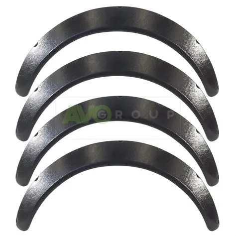
ABOUT FENDER:
Fender is the part of a car that protects and frames its wheels and keeps mud from splashing it. Most modern vehicles have fenders on their front wheels. It is the part of a car, truck or motorcycle that surrounds the wheel sell. The primary function of a fender is to prevent dirt and debris from being thrown into the air by the tire. The fender is located over the wheels of the vehicle. As such, there are four fenders on a typical vehicle: front right, front left, rear right and rear left.
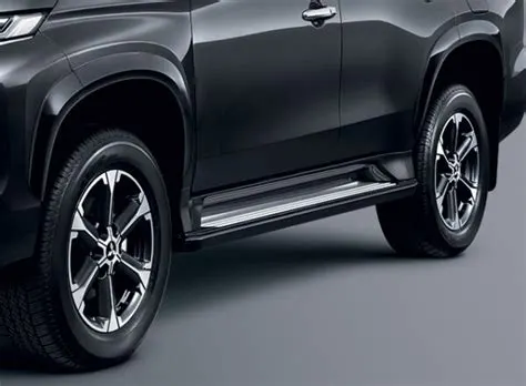
TYPES OF FENDER:
The type of fender is based upon the area covered i.e., full fender type and half fender type.
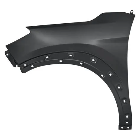
Full Fender Type Half Fender Type
- FULL FENDER TYPE: Full fender type is traditional type of fender where more material consumption is observed. This type is used in old design of automobiles where it increases the overall weight and thus reduces performance. The maintenance also relatively more due to more surface.
- HALF FENDER TYPE: Half fender type is modern design where less material consumption is observed, so productivity increases by reducing size of blank and thus providing more performance. The maintenance also relatively low compared to full bumper type.
JAPAN REQUIREMENTS FOR FENDER WHEEL ARC:
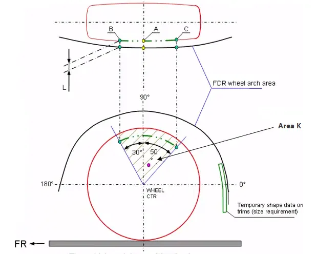
- Measure clearance L of tire, hub, cap, and fender in three different positions within area K and produce clearance check chart to validate.
- Clearance must be greater than 5mm in all the three positions.
- Wheel guard requirement: the value a shall be more than 5mm at a line 30*forward and 50*rearward from the central vertical axis of axis of wheel.
US STANDARDS REGULATION FOR FENDER WHEEL ARC:

- Make clearance check details on all positions from -100* to 100* and make the clearance check table.
- All values should be greater than 5mm to satisfy the regulation.
- The value of ‘a’ shall be more than 5mm at a line 30* forward and 50*rearward from the central vertical axis of axis of wheel.
EUROPEAN REGULATION:
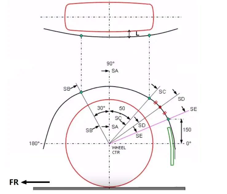
Measure CL L at section SA-SA-SB-SB-SC-SC-SD-SD-SE-SE and produce CL check chart to validate.
- At all five sections the CL L value should be greater than 10mm to satisfy the European regulations.
- Wheel guard requirement: the value of ‘a’ shall be more than 5mm at a line 30*forward and 50*rearward from the central vertical axis of axis of wheel.
FEBDER -WHEEL ARCH Design Producer:
- According to the European standards, the design fender and wheel arc should pass the wheel guard requirement procedures.
- To start the test, first create a plane with origin as center of the wheel plane.
- Then sketch using lines along with given dimensions as SA, SB, SC, SD and SE.
- After sketching project the intersection points on to the fender face.
- Then use measure distance tool and calculate the clearance between sketch lines and wheel arc.
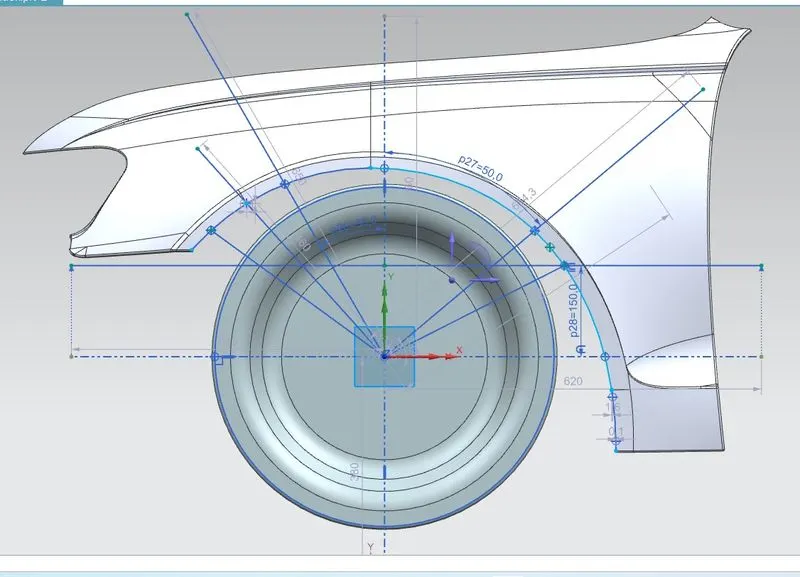
>The above image represents the fender with the wheel arch which we are going to measure the clerance between the fender and wheel arch through specified distance between the two points.
>Accodring to european standards the distance between the fender and wheel is 10mm,by basing on the 10mm we are going to measure the distance through specified points across the wheel.
Case-1(SA):
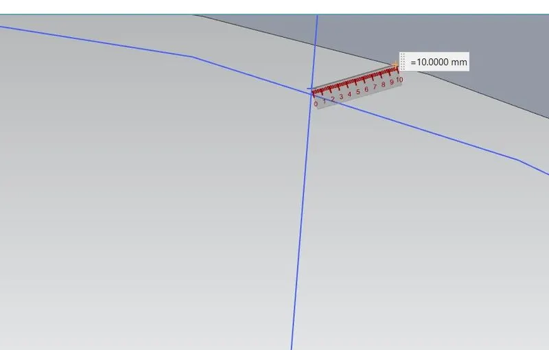
>The above image which is an SA where the clearance is 10mm and the test case is passed at this region.
Case-2(SB):
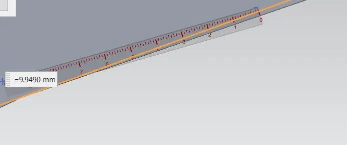
>Here the clearance is as 9.940mm whcih is an near to the 10mm ,so the test case is also accepted
Case-3(SC):
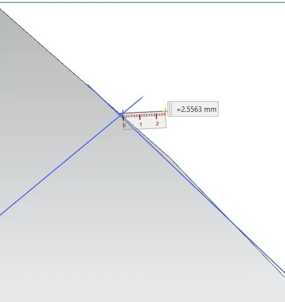
>Here in the case 3 the clerance is 2.55 which is less than to the 10mm according to european standards and the test case was faile at this region
CASE-4(SD):
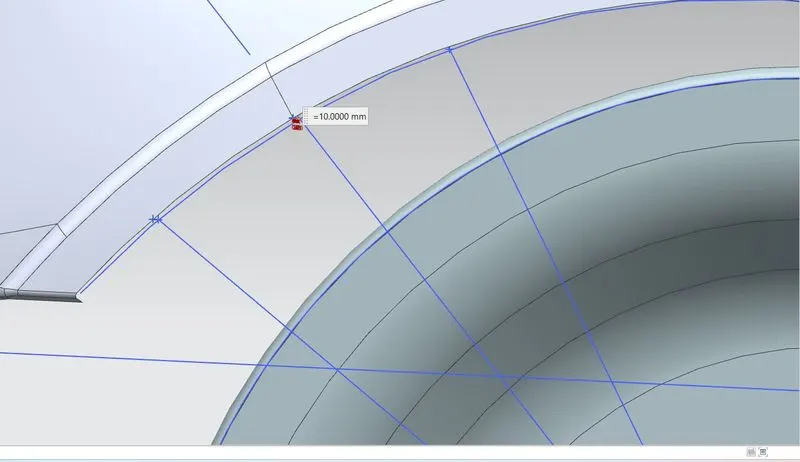
>Here we are considered the region at the lest side of the wheel arch,from that region the clerance between the two regions is as 10.00mm and the test case was also accepted.
CASE-5(SE):
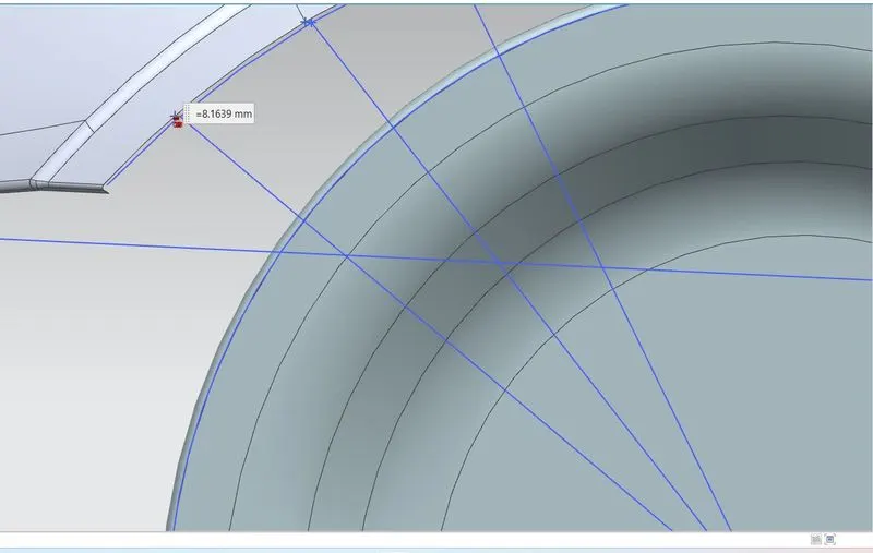
>In this the clerance between the two point is as 8.169mm which is an nearly to the 10mm and the region is partially acceptable.
CONCULSION:
>By observing all the above case we can conculde that the some of regions was not maintained the standards.
>The tabulated form represents all the above test cases which where accptebale and unacceptable.
| Region | Standard Clearance | Resulted Clearance | Results |
| SA | 10.00mm | 10.00mm | Passed |
| SB | 10.00mm | 9.9490mm | Acceptable |
| SC | 10.00mm | 2.563mm | Failed |
| SD | 10.00mm | 10.00mm | Passed |
| SE | 10.00mm | 8.169mm | Partially Acceptable |